Installation and User Guide
Labcom 221 BAT
Data transfer unit
![]()

![]()
DOC002199-EN-1
11/3/2023
1 General information about the manual
This manual is an integral part of the product.
- Please read the manual before using the product.
- Keep the manual available for the entire duration of the product’s life span.
- Provide the manual to the next owner or user of the product.
- Please report any errors or discrepancies related to this manual before commissioning the device.
1.1 Conformity of the product
The EU declaration of conformity and the product’s technical specifications are integral parts of this document.
All of our products have been designed and manufactured with due consideration to the essential European standards, statutes and regulations.
Labkotec Oy has a certified ISO 9001 quality management system and ISO 14001 environmental management system.
1.2 Limitation of liability
Labkotec Oy reserves the right to make changes to this user guide.
Labkotec Oy cannot be held liable for direct or indirect damage caused by neglecting the instructions provided in this manual or directives, standards, laws and regulations regarding the installation location.
The copyrights to this manual are owned by Labkotec Oy.
1.3 Used symbols
Safety related signs and symbols
![]() DANGER!
DANGER!
This symbol indicates a warning about a possible fault or danger. In case of ignoring the consequences may range from personal injury to death.
![]() WARNING!
WARNING!
This symbol indicates a warning about a possible fault or danger. In case of ignoring the consequences may cause personal injury or damage to the property.
![]() CAUTION!
CAUTION!
This symbol warns of a possible fault. In case of ignoring the device and any connected facilities or systems may be interrupted or fail complete.
2 Safety and the environment
2.1 General safety instructions
The plant owner is responsible for the planning, installation, commissioning, operation, maintenance and disassembly at the location.
Installation and commissioning of the device may be performed by a trained professional only.
Protection of operating personnel and the system is not ensured if the product is not used in accordance with its intended purpose.
Laws and regulations applicable to the usage or the intended purpose must be observed. The device has been approved for the intended purpose of use only. Neglecting these instructions will void any warranty and absolve the manufacturer from any liability.
All installation work must be carried out without voltage.
Appropriate tools and protective equipment must be used during installation.
Other risks at the installation site must be taken into account as appropriate.
2.2 Intended use
Labcom 221 GPS is primarily intended for transferring measurement, accrual, positioning, alarm and status information to the LabkoNet server from locations where there is no fixed power supply or installing it would be too expensive.
An LTE-M / NB-IoT network must be available for the device for data transfer. An external antenna can also be used for data transfer. The positioning functionalities require a satellite connection to the GPS system. The positioning (GPS) antenna is always internal, and there is no support for an external antenna.
A more specific description of the product’s operation, installation and use is provided later in this guide.
The device must be used in accordance with the instructions provided in this document. Other use is counter to the product’s purpose of use. Labkotec cannot be held liable for any damage caused by using the device in violation of its purpose of use.
2.3 Transport and storage
Check the packaging and its content for any possible damage.
Ensure that you have received all the ordered products and that they are as intended.
Keep the original package. Always store and transport the device in the original packaging.
Store the device in a clean and dry space. Observe the permitted storage temperatures. If the storage temperatures have not been presented separately, the products must be stored in conditions that are within the operating temperature range.
2.4 Repair
The device may not be repaired or modified without the manufacturer’s permission. If the device exhibits a fault, it must be delivered to the manufacturer and replaced with a new device or one repaired by the manufacturer.
2.5 Decommissioning and disposal
The device must be decommissioned and disposed of in compliance with local laws and regulations.
3 Product description
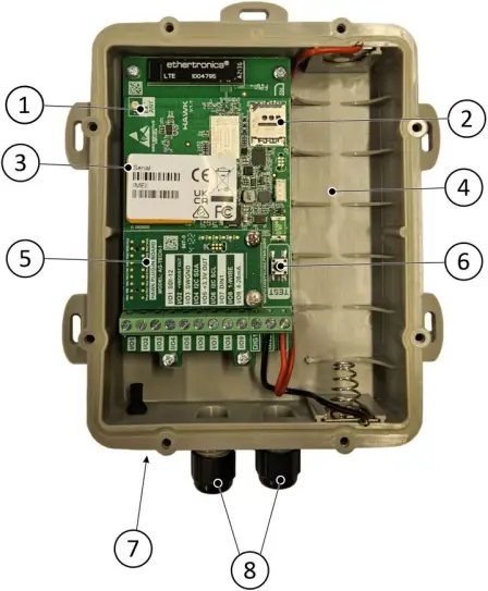 Figure 1 . Labcom 221 BAT product description
- Internal external antenna connector
- SIM card slot
- Device serial number = device number (also on the device cover)
- Batteries
- Additional card
- TEST button
- External antenna connector (option)
- Connection wire lead-throughs
4 Installation and commissioning
The device must be installed on a firm foundation where it is not at immediate risk of physical impacts or vibrations.
The device features screw holes for installation, as shown in the measurement drawing.
The cables to be connected to the device must be installed in such a way that prevents moisture from reaching the lead-throughs.
 Figure 2 . Labcom 221 BAT measurement drawing and installation dimensions (mm)
The device features preset configurations and parameters and comes with a SIM card installed. DO NOT remove the SIM card.
Ensure the following in the context of commissioning before installing batteries, see Batteries on page 14 ( 1 ):
- The wires have been installed correctly and tightened firmly to the terminal strips.
- If installed, the antenna wire has been tightened properly to the antenna connector in the housing.
- If installed, the internal antenna wire installed in the device has stayed connected.
- All lead-throughs have been tightened to keep moisture out.
Once all of the above are in order, the batteries can be installed and the device cover can be closed. When closing the cover, make sure that the cover seal is seated correctly to keep dust and moisture out of the device.
After installing the batteries, the device automatically connects to the LabkoNet server. This is indicated by the circuit board LEDs flashing.
The commissioning of the device is confirmed with the LabkoNet server by checking that the device has sent the correct information to the server.
5 Connections
![]() Read the section General safety instructions before installation.
Read the section General safety instructions before installation.
![]() Make the connections when the device is de-energised.
Make the connections when the device is de-energised.
5.1 Passive mA sensor
Labcom 221 BAT supplies the measuring circuit of the passive transmitter/sensor with the operating voltage required by the sensor. The plus lead of the measuring circuit is connected to the voltage input of the Labcom 221 BAT (+Vboost Out, I/O2) and the ground lead of the circuit is connected to the analogue input of the device (4-20mA, I/O9). The end of the Protective Earth (PE) wire is insulated either with tape or shrink wrap and left free.
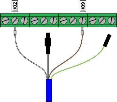
Figure 3 . Example connection.
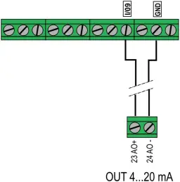
5.2 Active mA sensor
The voltage to the measurement circuit of the active measurement transmitter/sensor is supplied by the transmitter/sensor itself. The measurement circuit’s plus conductor is connected to the Labcom 221 GPS device’s analogue input (4-20 mA, I/O9) and the circuit’s grounding conductor is connected to the grounding connector (GND).
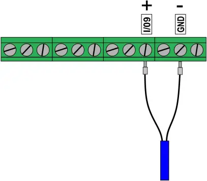
Figure 4 . Example connection
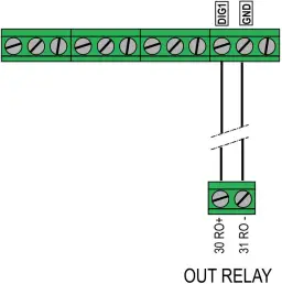
5.3 Switch output
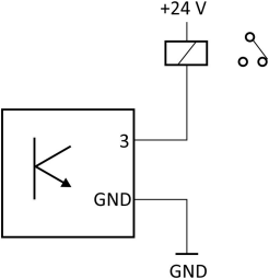
Figure 5 . Example connection
The Labcom 221 BAT device has one digital output. The approved voltage range is 0…40VDC and the maximum current is 1A. For larger loads, a separate auxiliary relay must be used, which is controlled by the Labcom 221 BAT.
5.4 Switch inputs
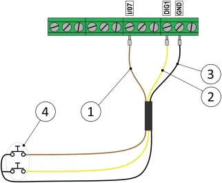
Figure 6 . Example connections
1 brown I/O7
2 yellow DIG1
3 black GND
4 Two separate switches
5.5 Example connections
5.5.1 Connection idOil-LIQ
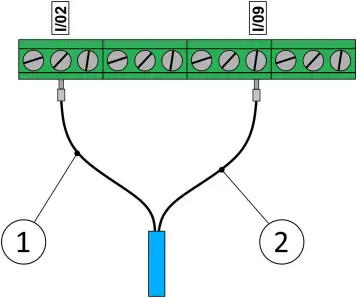
Figure 7 . idOil-LIQ sensor connection
1 black I/O2
2 black I/O9
![]() The Labcom 221 BAT data transfer unit + idOil-LIQ sensor must not be installed in potentially explosive atmospheres.
The Labcom 221 BAT data transfer unit + idOil-LIQ sensor must not be installed in potentially explosive atmospheres.
5.5.2 Connection idOil-SLU

Figure 8 . idOil-SLU sensor connection
1 black I/O2
2 black I/O9
![]() The Labcom 221 BAT data transfer unit + idOil-LIQ sensor must not be installed in potentially explosive atmospheres.
The Labcom 221 BAT data transfer unit + idOil-LIQ sensor must not be installed in potentially explosive atmospheres.
5.5.3 Connection idOil-OIL

Figure 9 . idOil-OIL sensor connection
1 black I/O2
2 black I/O9
![]()
The Labcom 221 BAT data transfer unit + idOil-OIL sensor must not be installed in potentially explosive atmospheres.
5.5.4 Connection GA-SG1

Figure 10 . GA-SG1 sensor connection
1 black I/O2
2 black I/O9
5.5.5 Connection SGE25
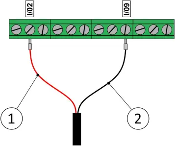
Figure 11 . SGE25 sensor connection
1 red I/O2
2 black I/O9
5.5.6 Connection 1-wire temperature sensor
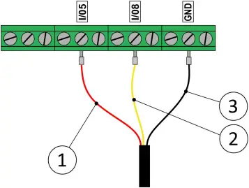
Figure 12 . 1-wire temperature sensor connection
1 red I/O5
2 yellow I/O8
3 black GND
5.5.7 Connection DMU-08 and L64
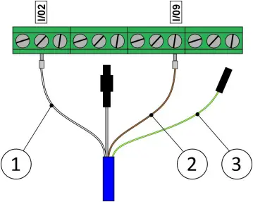
Figure 13 .DMU-08 and L64 sensors connection
1 white I/O2
2 brown I/O9
3 PE Insulate the wire
If the DMU-08 sensor is to be connected, a cable extension (e.g. LCJ1-1) should be used to connect the DMU-08 sensor wires to the device and from which a separate cable is connected to the line connectors of the Labcom 221 BAT (not included). The end of the Protective Earth (PE) wire shall be insulated either by taping or shrink-wrap and left free.
5.5.8 Connection Nivusonic CO 100 S
Nivusonic measurement circuit connection
Nivusonic relay tip connection (pos. pulse)
Nivusonic optical tip connection (neg. pulse)

Figure 14 . Nivusonic CO 100 S connection
5.5.9 Connection MiniSET/MaxiSET
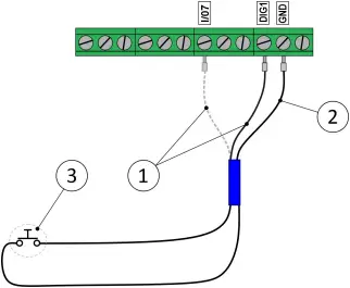
Figure 15 . Example connection
1 black DIG1 or I/O7
2 black GND
3 switch
The sensor cable is connected to the instrument’s ground terminal (GDN). The second sensor lead can be connected to the DIG1 or I/07 connector. By default, the sensor operates as an upper limit alarm. If the sensor is to act as a lower limit alarm, the sensor float switch must be removed and reversed
6 Batteries
The Labcom 221 BAT is battery powered. The device is powered by two 3.6V lithium batteries (D/R20), which can provide up to more than ten years of operation. The batteries are easily replaceable.
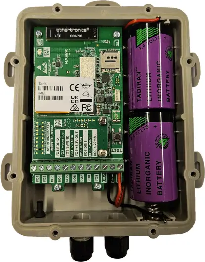 Figure 16 Labcom 221 BAT batteries
Battery information:
Type: Lithium
Size: D/R20
Voltage: 3.6V
Amount: Two (2) pcs
Max. power: At least 200mA
7 Troubleshooting FAQ
If the instructions in this section do not help with rectifying the problem, write down the device number and primarily contact the seller of the device or alternatively the e-mail address labkonet@labkotec.fi or Labkotec Oy’s customer support +358 29 006 6066.
| PROBLEM | SOLUTION |
| The device does not contact the LabkoNet server = connection failure | Open the device cover and press the TEST button on the right side of the circuit board (if the device is in the vertical position) for three (3) seconds. This forces the device to contact the server. |
| The device is connected to the server, but the measurement/accrual data is not updated to the server. | Make sure that the sensor/transmitter is in order. Check that the connections and conductors are tightened to the terminal strip. |
| The device is connected to the server, but the positioning data is not updated. | Change the installation location of the device so that it connects to the positioning satellite. |
8 Technical specifications Labcom 221 BAT
TECHNICAL SPECIFICATIONS Labcom 221 BAT
| Dimensions | 185 mm x 150 mm x 30 mm |
| Enclosure | IP 68 IP 67 when using an external antenna (option) IK08 (Impact protection) |
| Weight | 310 g |
| Lead-throughs | Cable diameter 2.5-6.0 mm |
| Operating environment | Temperature: -30ºC…+60ºC |
| Supply voltage | Internal 2 pcs 3.6V Lithium batteries (D,R20)
External 6-28 VDC, however over 5 W |
| Antennas (*) | GSM antenna internal/external
GPS antenna internal |
| Data transfer | LTE-M / NB-IoT Encryption AES-256 and HTTPS |
| Positioning | GPS |
| Measurement inputs (*) | 1 pc 4-20 mA +/-10 µA 1 pc 0-30 V +/- 1 mV |
| Digital inputs (*) | 2 pcs 0-40 VDC, alarm and counter function for inputs |
| Switch outputs (*) | 1 pc digital output, max 1 A, 40 VDC |
| Other connections (*) | SDI12, 1-wire, i2c-bus and Modbus |
| Approvals: | |
| Health and Safety | IEC 62368-1 EN 62368-1 EN 62311 |
| EMC | EN 301 489-1 EN 301 489-3 EN 301 489-19 EN 301 489-52 |
| Radio Spectrum Efficiency | EN 301 511 EN 301 908-1 EN 301 908-13 EN 303 413 |
| RoHS | EN IEC 63000 |
| Article 10(10) and 10(2) | No operating restrictions in any EU Member State. |
(*) depends on the device configuration
![]() DOC002199-EN-1
DOC002199-EN-1
Documents / Resources
 |
Labkotec Labcom 221 BAT Data Transfer Unit [pdf] User Guide Labcom 221 BAT Data Transfer Unit, Labcom 221 BAT, Data Transfer Unit, Transfer Unit, Unit |


