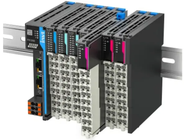
invt FK1100 Dual Channel Incremental Encoder Detection Module
Product Usage Instructions
- The FL6112 dual-channel incremental encoder detection module supports quadrature A/B signal input with an input voltage of 24V.
- It also supports x1/x2/x4 frequency multiplication modes. Each channel has a digital signal input and output with a voltage of 24V.
- Ensure proper wiring following the provided cable specifications.
- Connect the external power supply rated at 24V and 0.5A to power the module and the connected encoder.
- Ensure proper isolation and protection against reverse connection and overcurrent.
- The module supports speed and frequency measurement using the connected encoder signals.
- Ensure proper detection of A/B/Z encoder signals, digital input signals, and digital output signals for accurate data processing.
- Refer to the manual for common parameter settings such as counter presets, pulse modes, and DI detection electrical levels.
- Troubleshoot common faults like power connection issues or incorrect parameter settings using the indicator lights.
FAQ
- Q: What is the maximum encoder input frequency supported by the FL6112 module?
- A: The module supports a maximum encoder input frequency of 200kHz.
- Q: What type of encoder signals does each channel support?
- A: Each channel supports quadrature A/B signal input with an input voltage of 24V.
Preface
Overview
Thank you for choosing INVT FL6112 dual-channel incremental encoder detection module. The FL6112 dual-channel incremental encoder detection module is compatible with INVT FLEX series communication interface modules (such as FK1100, FK1200, and FK1300), TS600 series programmable controller, and TM700 series programmable controller. The FL6112 dual-channel incremental encoder detection module has the following features:
- The module supports the incremental encoder input of two channels.
- Each encoder channel supports A/B incremental encoder or pulse direction encoder input.
- Each encoder channel supports the quadrature A/B signal input with an input voltage of 24V, and supports the source and sink types.
- The incremental encoder mode supports x1/x2/x4 frequency multiplication modes.
- Each encoder channel supports 1 digital signal input with an input voltage of 24V.
- Each encoder channel supports 1 digital signal output with an output voltage of 24V.
- The module provides one 24V power output for the encoder to power the connected encoder.
- The module supports a maximum encoder input frequency of 200kHz.
- The module supports speed measurement and frequency measurement.
This guide briefly describes the interface, wiring examples, cable specifications, usage examples, common parameters, and common faults and solutions of the INVT FL6112 dual-channel incremental encoder detection module.
Audience
- Personnel with electrical professional knowledge (such as qualified electrical engineers or personnel with equivalent knowledge).
Change History
- The manual is subject to change irregularly without prior notice due to product version upgrades or other reasons.
| No. | Change description | Version | Release date |
| 1 | First release. | V1.0 | July 2024 |
Specifications
| Item | Specifications | |||
|
Power supply |
External input-rated voltage | 24VDC (-15% – +20%) | ||
| External input rated current | 0.5A | |||
| Backplane bus
rated output voltage |
5VDC (4.75VDC–5.25VDC) |
|||
| Backplane bus current
consumption |
140mA (Typical value) |
|||
| Isolation | Isolation | |||
| Power supply protection | Protection against reverse connection and overcurrent | |||
|
Indicator |
Name | Color | Silk
screen |
Definition |
|
Run indicator |
Green |
R |
On: The module is running. Slow flashing (once every 0.5s): The module is establishing communication.
Off: The module is not powered on or it is abnormal. |
|
|
Error indicator |
Red |
E |
Off: No abnormalities were found during module operation.
Fast flashing (once every 0.1s): The module is offline. Slow flashing (once every 0.5s): No power connected externally or incorrect parameter settings. |
|
| Channel indicator | Green | 0 | Enabling channel 0 encoder | |
| 1 | Enabling channel 1 encoder | |||
|
A/B/Z encoder signal detection |
Green |
A0 |
On: The input signal is valid. Off: The input signal is invalid. |
|
| B0 | ||||
| Z0 | ||||
| A1 | ||||
| B1 | ||||
| Z1 | ||||
| Item | Specifications | |||
| Digital input
signal detection |
Green | X0 | On: The input signal is valid.
Off: The input signal is invalid. |
|
| X1 | ||||
| Digital output
signal indication |
Green | Y0 | On: Enable output.
Off: Disable output. |
|
| Y1 | ||||
| Connected
encoder type |
Incremental encoder | |||
| Number of
channels |
2 | |||
| Encoder voltage | 24VDC ± 15% | |||
| Counting range | -2147483648 – 2147483647 | |||
| Pulse mode | Phase difference pulse/pulse+direction input (supports
directionless signals) |
|||
| Pulse frequency | 200kHz | |||
| Frequency multiplication
mode |
x1/x2/x4 |
|||
| Resolution | 1–65535PPR (pulses per revolution) | |||
| Counter preset | Default is 0, which means the preset is disabled. | |||
| Z-pulse
calibration |
Supported by default for Z signal | |||
| Counter filter | (0–65535)*0.1μs per channel | |||
| Number of DIs | 2 | |||
| DI detection
electrical level |
24VDC | |||
| DI edge
selection |
Rising edge/Falling edge/Rising or falling edge | |||
| DI wiring type | Source (PNP)-type /Sink (NPN)-type wiring | |||
| DI filter time
setting |
(0–65535)*0.1μs per channel | |||
| Latched value | Total latched values and latch completion flags | |||
| ON/OFF
response time |
At the μs level | |||
| DO channel | 2 | |||
| DO output level | 24V | |||
| DO output form | Source-type wiring, max. current 0.16A | |||
| DO function | Comparison output | |||
| DO voltage | 24VDC | |||
| Measurement | Frequency/Speed | |||
| Item | Specifications | |
| variable | ||
| The update time of the measurement
function |
Four levels: 20ms, 100ms, 500ms, 1000ms |
|
| Gating function | Software gate | |
| Certification | CE, RoHS | |
|
Environment |
Ingress protection (IP)
rating |
IP20 |
| Working
temperature |
-20°C–+55°C | |
| Working humidity | 10%–95% (no condensation) | |
| Air | No corrosive gas | |
| Storage
temperature |
-40°C–+70°C | |
| Storage humidity | RH < 90%, without condensation | |
| Altitude | Lower than 2000m (80kPa) | |
| Pollution degree | ≤2, compliant with IEC61131-2 | |
| Anti-interference | 2kV power cable, compliant with IEC61000-4-4 | |
| ESD class | 6kVCD or 8kVAD | |
| EMC
anti-interference level |
Zone B, IEC61131-2 |
|
|
Vibration resistant |
IEC60068-2-6
5Hz–8.4Hz, vibration amplitude of 3.5mm, 8.4Hz–150Hz, ACC of 9.8m/s2, 100 minutes at each direction of X, Y, and Z (10 times and 10 minutes each time, for a total of 100 minutes) |
|
| Impact resistance |
Impact resistance |
IEC60068-2-27
50m/s2, 11ms, 3 times for each of 3 axes at each direction of X, Y, and Z |
| Installation
method |
Rail installation: 35mm standard DIN rail | |
| Structure | 12.5×95×105 (W×D×H, unit: mm) | |
Interface description
| Schematic diagram | Left signal | Left terminal | Right terminal | Right signal |
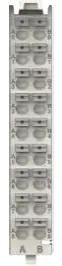 |
A0 | A0 | B0 | A1 |
| B0 | A1 | B1 | B1 | |
| Z0 | A2 | B2 | Z1 | |
| DI0 | A3 | B3 | DI1 | |
| SS | A4 | B4 | SS | |
| VO | A5 | B5 | COM | |
| PE | A6 | B6 | PE | |
| DO0 | A7 | B7 | DO1 | |
| 24V | A8 | B8 | 0V |
| Pin | Name | Description | Specifications |
| A0 | A0 | Channel 0 encoder A-phase input | 1. Internal impedance: 3.3kΩ
2. 12–30V voltage input is acceptable 3. Supports sink input 4. Max. input frequency: 200kHz |
| B0 | A1 | Channel 1 encoder A-phase input | |
| A1 | B0 | Channel 0 encoder B-phase input | |
| B1 | B1 | Channel 1 encoder B-phase input | |
| A2 | Z0 | Channel 0 encoder Z-phase input | |
| B2 | Z1 | Channel 1 encoder Z-phase input | |
| A3 | DI0 | Channel 0 digital input | 1. Internal impedance: 5.4kΩ
2. 12–30V voltage input is acceptable 3. Supports sink input 4. Max. input frequency: 200Hz |
| B3 | DI1 | Channel 1 digital input | |
| A4 | SS | Digital input/Encoder common port | |
| B4 | SS | ||
| A5 | VO | External 24V power supply positive |
Power output: 24V±15% |
| B5 | COM | External 24V power supply negative | |
| A6 | PE | Low-noise ground | Low noise grounding points for the module |
| B6 | PE | Low-noise ground | |
| A7 | DO0 | Channel 0 digital output | 1. Supports source output
2. Max. output frequency: 500Hz 3. Max. withstand current of single channel: < 0.16A |
|
B7 |
DO1 |
Channel 1 digital output |
|
| A8 | +24V | Module 24V power input positive | Module power input: 24V±10% |
| B8 | 0V | Module 24V power input negative |
Wiring examples
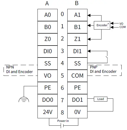
Note
- The shielded cable should be used as the encoder cables.
- The terminal PE needs to be well grounded through a cable.
- Do not bundle the encoder cable with the power line.
- The encoder input and digital input share a common terminal SS.
- When using modules to power the encoder, for the NPN encoder input interface, short circuit SS and VO; for the PNP encoder input interface, short circuit SS to COM.
- When using external power supply to power the encoder, for the NPN encoder input interface, short circuit SS and the positive pole of the external power supply; for the PNP encoder input interface, short circuit SS to the negative pole of the external power supply.
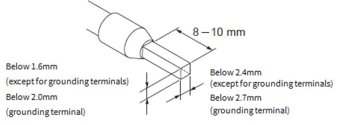
Cable specifications
| Cable material | Cable diameter | Crimping tool | |
| mm2 | AWG | ||
|
Tubular cable lug |
0.3 | 22 |
Use a proper crimping plier. |
| 0.5 | 20 | ||
| 0.75 | 18 | ||
| 1.0 | 18 | ||
| 1.5 | 16 | ||
Note: The cable diameters of the tubular cable lugs in the preceding table is only for reference, which can be adjusted based on actual situations.
When using other tubular cable lugs, crimp multiple strands of cable, and the processing size requirements are as follows:
Application example
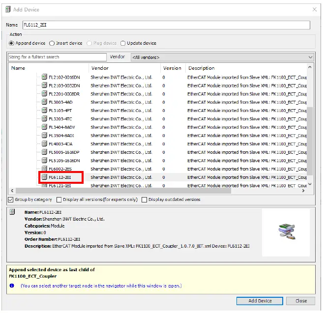
- This chapter takes CODESYS as an example to introduce the usage of the product. Step 1 Add the FL6112_2EI device.
- Step 2 Choose Startup Parameters, set the counter, filtering mode, encoder resolution, and counter preset values based on the actual needs, with a filter unit of 0.1μs.
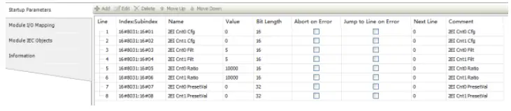
- Cntx Cfg(x=0,1) is the counter configuration parameter of type UINT. Taking the counter 0 configuration as an example, the data definition can be found in the parameter description.
| Bit | Name | Description |
|
Bit1–bit0 |
Channel mode |
00: A/B phase quadruple frequency; 01: A/B phase double frequency
10:A/B phase rated frequency; 11: Pulse+direction |
|
Bit3–bit2 |
Frequency measurement period |
00: 20ms; 01: 100ms; 10: 500ms; 11: 1000ms |
| Bit5–bit4 | Edge latch enabling | 00: Disabled; 01: Rise edge; 10: Fall edge; 11: Two edges |
| Bit7–bit6 | Reserved | Reserved |
|
Bit9–bit8 |
Pulse output width when the comparison is consistent |
00: 1ms; 01: 2ms; 10: 4ms; 11: 8ms |
|
Bit11–bit10 |
DO comparison output mode |
00: Output when the comparison is consistent
01: Output when the difference between [lower limit of count, comparison value] 10: Output when the difference between [comparison value, upper limit of count] 11: Reserved |
| Bit15–bit12 | Reserved | Reserved |
Assuming that counter 0 is configured as A/B phase quadruple frequency, the frequency measurement period is 100ms, DI0 rising edge latch is enabled, and the mode is set to output 8ms pulse when the comparison is consistent, Cnt0 Cfg should be configured as 788, i.e. 2#0000001100010100, as detailed below.
| Bit15– bit12 | Bit11 | Bit10 | Bit9 | Bit8 | Bit7 | Bit6 | Bit5 | Bit4 | Bit3 | Bit2 | Bit1 | Bit0 |
| 0000 | 00 | 11 | 00 | 01 | 01 | 00 | ||||||
|
Reserved |
Output when comparison is consistent |
8ms |
Reserved |
Rising edge |
100ms |
A/B phase quadruple frequency | ||||||
- Cntx Filt(x=0,1) is the filter parameter of A/B/Z/DI port with a unit of 0.1μs. If it is set to 10, it means that only signals that remain stable and do not jump within 1μs are sampled.
- Cntx Ratio(x=0,1) is the encoder resolution (number of pulses fed back from one revolution, i.e. the pulse increment between two Z pulses). Assuming the resolution labeled on the encoder is 2500P/R, the Cnt0 Ratio should be set to 10000 since the Cnt0 Cfg is configured as A/B phase quadruple.
- Cntx PresetVal(x=0,1) is the counter preset value of type DINT.
- Step 3 After configuring the above startup parameters and downloading the program, control the counter on the Module I/O mapping interface.
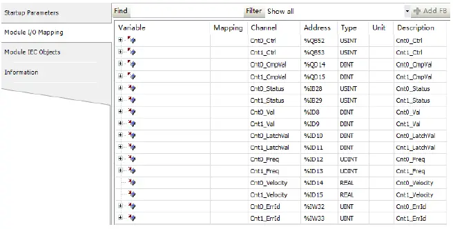
- Cntx_Ctrl(x=0,1) is the counter control parameter. Taking the counter 0 as an example, the data definition can be found in the parameter description.
| Bit | Name | Description |
| Bit0 | Enable counting | 0: Disable 1: Enable |
| Bit1 | Clear count value | Effective at the rising edge |
| Bit2 | Write the counter preset value | Effective at the rising edge |
| Bit3 | The clear count overflow flag | Effective at the rising edge |
| Bit4 | Counter comparison | 0: Disable 1: Enable |
| Bit7–bit5 | Reserved | Reserved |
- Cntx_CmpVal(x=0,1) is the counter comparison value of type DINT.
- Assuming that Cnt0_CmpVal is set to 1000000 and you want to enable the counter for comparison, set Cnt0_Ctrl to 17, which is 2#00010001. The details are as follows.
| Bit7–bit5 | Bit4 | Bit3 | Bit2 | Bit1 | Bit0 |
| 000 | 1 | 0 | 0 | 0 | 1 |
| Reserved | 1: Enable | Effective at the rising edge | Effective at the rising edge | Effective at the rising edge | 1: Enable |
According to the configuration value 788 of Cnt0 Cfg mentioned above (enabling DO to output pulse 8ms when the comparison is consistent), when the count value Cnt0_Val is equal to 1000000, DO0 will output 8ms.
To clear the current count value of counter 0, set Cnt0_Ctrl to 2, which is 2#00000010. The details are as follows.
| Bit7–bit5 | Bit4 | Bit3 | Bit2 | Bit1 | Bit0 |
| 000 | 0 | 0 | 0 | 1 | 0 |
| Reserved | 0: Disabled | Effective at the rising edge | Effective at the rising edge | Effective at the rising edge | 0: Disabled |
- At this point, the bit1 of Cnt0_Ctrl changes from 0 to 1. The FL6112_2EI module monitors the rising edge of this bit and clears the count value of counter 0, which means Cnt0_Val is cleared.
Appendix A Parameter description
| Parameter name | Type | Description |
| 2EI Cnt0 Cfg | UINT | Configuration parameter for counter 0: Bit1–bit0: Channel mode configuration
00: A/B phase quadruple frequency; 01: A/B phase double frequency; 10: A/B phase rated frequency; 11: Pulse+direction (high level, positive) Bit3–bit2: Frequency measurement period 00: 20ms; 01: 100ms; 10: 500ms; 11: 1000ms Bit5–bit4: Edge latch count value enabling 00: Disabled; 01: Rise edge; 10: Fall edge; 11: Two edges Bit7–bit6: Reserved Bit9–bit8: Pulse output width when comparison is consistent 00: 1ms; 01: 2ms; 10: 4ms; 11: 8ms Bit11–bit10: DO comparison output mode 00: Output when comparison is consistent; 01: Output between [lower limit of count, comparison value]; 10: Output between [comparison value, upper limit of count]; 11: Reserved (Output when comparison is consistent) Bit15–bit12: Reserved |
| 2EI Cnt1 Cfg | UINT | Configuration parameter for counter 1. The parameter configuration is consistent with counter 0. |
| 2EI Cnt0 Filt | UINT | Filtering parameter for counter 0 A/B/Z/DI port. Application scope 0–65535 (Unit: 0.1μs) |
| 2EI Cnt1 Filt | UINT | Filtering parameter for counter 1 A/B/Z/DI port. Application scope 0–65535 (Unit: 0.1μs) |
| 2EI Cnt0 Ratio | UINT | Encoder resolution for counter 0 (number of pulses fed back from one revolution, the pulse increment between two Z pulses). |
| 2EI Cnt1 Ratio | UINT | Encoder resolution for counter 1 (number of pulses fed back from one revolution, the pulse increment between two Z pulses). |
| 2EI Cnt0 PresetVal | DINT | Counter 0 preset value. |
| Parameter name | Type | Description |
| 2EI Cnt1 PresetVal | DINT | Counter 1 preset value. |
| Cnt0_Ctrl | USINT | Control parameter for counter 0.
Bit0: Enable counting, valid at high levels Bit1: Clear counting, valid at the rising edge Bit2: Write counter preset value, valid at the rising edge Bit3: Clear count overflow flag, valid at the rising edge Bit4: Enable count comparison function, valid at high levels (Provided that the counting is enabled.) Bit7–bit5: Reserved |
| Cnt1_Ctrl | USINT | Control parameter for counter 1. The parameter
configuration is consistent with counter 0. |
| Cnt0_CmpVal | DINT | Counter 0 comparison value |
| Cnt1_CmpVal | DINT | Counter 1 comparison value |
| Cnt0_Status | USINT | Counter 0 count state feedback Bit0: Forward run flag bit
Bit1: Reverse run flag bit Bit2: Overflow flag bit Bit3: Underflow flag bit Bit4: DI0 latch completion flag Bit7–bit5: Reserved |
| Cnt1_Status | USINT | Counter 1 count state feedback Bit0: Forward run flag bit
Bit1: Reverse run flag bit Bit2: Overflow flag bit Bit3: Underflow flag bit Bit4: DI1 latch completion flag Bit7–bit5: Reserved |
| Cnt0_Val | DINT | Count value of counter 0 |
| Cnt1_Val | DINT | Count value of counter 1 |
| Cnt0_LatchVal | DINT | Latched value of counter 0 |
| Cnt1_LatchVal | DINT | Latched value of counter 1 |
| Cnt0_Freq | UDINT | Counter 0 frequency |
| Cnt1_Freq | UDINT | Counter 1 frequency |
| Cnt0_Velocity | REAL | Counter 0 speed |
| Cnt1_Velocity | REAL | Counter 1 speed |
| Cnt0_ErrId | UINT | Counter 0 error code |
| Cnt1_ErrId | UINT | Counter 1 error code |
Appendix B Fault code
| Fault code (decimal) | Fault code (hexadecimal) |
Fault type |
Solution |
|
1 |
0x0001 |
Module configuration fault |
Ensure the correct mapping between module network configuration and physical configuration. |
| 2 | 0x0002 | Incorrect module
parameter setting |
Ensure that module parameter
settings are correct. |
| 3 | 0x0003 | Module output port power supply fault | Ensure that the module output port power supply is normal. |
|
4 |
0x0004 |
Module output fault |
Ensure that the module output
port load is within the specified range. |
|
18 |
0x0012 |
Incorrect parameter setting for channel 0 | Ensure that the parameter settings for channel 0 are
correct. |
|
20 |
0x0014 |
Output fault on Channel 0 |
Ensure that the output of
channel 0 has no short circuit or open circuit. |
|
21 |
0x0015 |
Signal source open circuit fault on Channel 0 | Ensure that the signal source’s physical connection of the channel
0 is normal. |
|
22 |
0x0016 |
Sampling signal limit
exceeding fault on Channel 0 |
Ensure that the sampling signal
on channel 0 does not exceed the chip limit. |
|
23 |
0x0017 |
Sampling signal measurement upper limit exceeding fault on
channel 0 |
Ensure that the sampling signal on channel 0 does not exceed the measurement upper limit. |
|
24 |
0x0018 |
Sampling signal measurement lower limit exceeding fault on
channel 0 |
Ensure that the sampling signal on channel 0 does not exceed the measurement lower limit. |
|
34 |
0x0022 |
Incorrect parameter setting for channel 1 | Ensure that the parameter
settings for channel 1 are correct. |
| Fault
code (decimal) |
Fault code (hexadecimal) |
Fault type |
Solution |
|
36 |
0x0024 |
Output fault on Channel 1 |
Ensure that the output of channel 1 has no short circuit or open circuit. |
|
37 |
0x0025 |
Signal source open circuit fault on Channel 1 | Ensure that the signal source physical connection of channel 1 is normal. |
|
38 |
0x0026 |
Sampling signal limit exceeding fault on Channel 1 | Ensure that the sampling signal on channel 1 does not exceed the chip limit. |
|
39 |
0x0027 |
Sampling signal measurement upper limit exceeding fault on Channel 1 | Ensure that the sampling signal on channel 1 does not exceed the measurement upper limit. |
|
40 |
0x0028 |
Sampling signal measurement lower limit exceeding fault on channel 1 | Ensure that the sampling signal on channel 1 does not exceed the measurement lower limit. |
CONTACT
Shenzhen INVT Electric Co., Ltd.
- Address: INVT Guangming Technology Building, Songbai Road, Matian,
- Guangming District, Shenzhen, China
INVT Power Electronics (Suzhou) Co., Ltd.
- Address: No. 1 Kunlun Mountain Road, Science & Technology Town,
- Gaoxin District, Suzhou, Jiangsu, China

Website: www.invt.com

Manual information may be subject to change without prior notice.
Documents / Resources
 |
invt FK1100 Dual Channel Incremental Encoder Detection Module [pdf] User Guide FK1100, FK1200, FK1300, TS600, TM700, FK1100 Dual Channel Incremental Encoder Detection Module, FK1100, Dual Channel Incremental Encoder Detection Module, Channel Incremental Encoder Detection Module, Incremental Encoder Detection Module, Encoder Detection Module, Detection Module, Module |