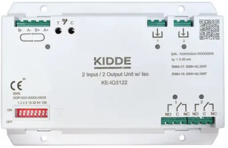
KIDDE KE-IO3122 Intelligent Addressable Two Four Input Output Module
Produktaj Uzado-Instrukcioj
AVERTO: Danĝero de elektrokuto. Certigu ĉian potencon sources are removed before installation.
Atentu: Follow EN 54-14 standards and local regulations for system planning and design.
- Use the NeXT System Builder application to determine maximum module kapacito.
- Install the module inside a compatible protective housing (ekz., N-IO-MBX-1 DIN Rail Modula Box).
- Earth is the protective housing.
- Mount the housing securely on the wall.
- Connect loop wires according to Table 1 and use recommended cable specifications from Table 2.
- Set the device address (001-128) using the DIP switch. Refer to the provided figures for configuration.
- The input mode is set at the control panel. Various modes are available with corresponding resistor requirements (refer to Table 3).
Oftaj Demandoj
- Q: Can I install the module outdoors?
- A: No, the module is suitable for indoor installation only.
- Q: How do I know the maximum distance for loop wiring?
- A: The maximum distance from the input terminal to the end of the line is 160m.
- Q: What firmware version is compatible with this module?
- A: The module is compatible with firmware version 5.0 or later for 2X-A Series fire alarm control panels.
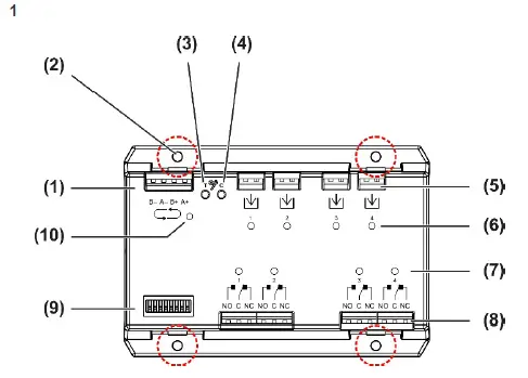
Figuro 1: Aparato finitaview (KE-IO3144)
- Buklo fina bloko
- Muntaj truoj (×4)
- Testo (T) butono
- Channel (C) button
- Input terminal blocks
- Eniga statusaj LEDoj
- Eligi statusajn LEDojn
- Output terminal blocks
- DIP-ŝaltilo
- Aparato statusa LED
Figuro 2: Eniga konektoj
- Normala reĝimo
- Bi-Level mode
- Normally Open mode
- Normally Closed mode

Priskribo
This installation sheet includes information on the following 3000 Series input/output modules.
| Modelo | Priskribo | Aparato tipo |
| KE-IO3122 | Intelligent addressable 2 input/output module with integrated short circuit isolator | 2IOni |
| KE-IO3144 | Intelligent addressable 4 input/output module with integrated short circuit isolator | 4IOni |
- Each module includes an integrated short circuit isolator and is suitable for indoor installation.
- Ĉiuj 3000-Serio-moduloj subtenas la Kidde Excellence-protokolon kaj estas kongruaj por uzo kun 2X-A Series fajroalarmkontrolpaneloj kun firmware versio 5.0 aŭ poste.
Instalado
AVERTO: Danĝero de elektrokuto. Por eviti personan vundon aŭ morton pro elektrokuto, forigu ĉiujn fontojn de potenco kaj lasu stokitan energion elŝargi antaŭ ol instali aŭ forigi ekipaĵon.
Atentu: For general guidelines on system planning, design, installation, commissioning, use, and maintenance, refer to the EN 54-14 standard and local regulations.
Instalante la modulon
- Ĉiam uzu la aplikaĵon NeXT System Builder por kalkuli la maksimuman nombron da moduloj instaleblaj.
- La modulo devas esti instalita ene de kongrua protekta loĝejo (ne liverita) − ni rekomendas la N-IO-MBX-1 DIN-Rail Modulan Box. Memoru surterligi la protektan loĝejon.
- Notu: Alternativa protekta loĝado povas esti uzata kondiĉe ke ĝi plenumas la specifojn indikitajn en "Protekta loĝejo" sur paĝo 4.
- Muntu la protektan loĝejon sur la muron uzante taŭgan muntan sistemon por la muraj trajtoj.
Kaptado de la modulo
Connect the loop wires as shown below. See Table 2 for recommended cable specifications.
Tablo 1: Buklokonekto
| Terminalo | Priskribo |
| B− | Negativa linio (–) |
| A− | Negativa linio (–) |
| B+ | Pozitiva linio (+) |
| A+ | Pozitiva linio (+) |
Tablo 2: Rekomenditaj kablospecifoj
| Kablo | Specifo |
| Buklo | 0.13 ĝis 3.31 mm² (26 ĝis 12 AWG) ŝirmita aŭ neŝirmita tordita paro (52 Ω kaj 500 nF maks.) |
| Eligo | 0.13 ĝis 3.31 mm² (26 ĝis 12 AWG) ŝirmita aŭ neŝirmita tordita paro |
| Input [1] | 0.5 ĝis 4.9 mm² (20 ĝis 10 AWG) ŝirmita aŭ neŝirmita tordita paro |
| [1] The maximum distance from the input terminal to the end of the line is 160 m. | |
- [1] The maximum distance from the input terminal to the end of the line is 160 m.
- See Figure 2 and “Input configuration” below for input connections.
Alparolante la modulon
- Agordu la aparatadreson per la DIP-ŝaltilo. La adresaro estas 001-128.
- The configured device address is the sum of the switches in the ON position, as shown in the figures below.

Eniga agordo
The module input mode is configured at the control panel (Field setup > Loop device configuration).
La disponeblaj reĝimoj estas:
- Normala
- Dunivela
- Normale Malferma (NE)
- Normale Fermita (NC)
Each input can be set to a different mode if required.
The resistors required for each mode are shown below.
Table 3: Input configuration resistors
| End-of-line resistor | Serio resistor [1] | Serio resistor [1] | |
| Reĝimo | 15 kΩ, ¼ W, 1% | 2 kΩ, ¼ W, 5% | 6.2 kΩ, ¼ W, 5% |
| Normala | X | X | |
| Dunivela | X | X | X |
| NE | X | ||
| NC | X | ||
| [1] With activation switch. | |||
Normala reĝimo
Normal mode is compatible for use in installations requiring EN 54-13 compliance.
Input activation characteristics for this mode are shown in the table below.
Table 4: Normal mode
| Ŝtato | Activation value |
| Mallonga cirkvito | < 0.3 kΩ |
| Aktiva 2 | 0.3 kΩ ĝis 7 kΩ |
| High resistance fault | 7 kΩ ĝis 10 kΩ |
| Kvieta | 10 kΩ ĝis 17 kΩ |
| Malferma cirkvito | > 17 kΩ |
Bi-Level mode
- Bi-Level mode is not compatible for use in installations requiring EN 54-13 compliance.
- Input activation characteristics for this mode are shown in the table below.
Table 5: Bi-Level mode
| Ŝtato | Activation value |
| Mallonga cirkvito | < 0.3 kΩ |
| Active 2 [1] | 0.3 kΩ ĝis 3 kΩ |
| Aktiva 1 | 3 kΩ ĝis 7 kΩ |
| Kvieta | 7 kΩ ĝis 27 kΩ |
| Malferma cirkvito | > 27 kΩ |
| [1] Active 2 takes priority over Active 1. | |
Normally Open mode
In this mode, a short circuit is interpreted as active at the control panel (only open circuit faults are notified).
Normally Closed mode
In this mode, an open circuit is interpreted as active at the control panel (only short circuit faults are notified).
Indikoj de stato
- La stato de la aparato estas indikita per la LED-Stato de Aparato (Figuro 1, ero 10), kiel montrite en la suba tabelo.
Tablo 6: Aparato-statusaj LED-indikoj
| Ŝtato | Indiko |
| Aktiva izolado | Konstanta flava LED |
| Aparato misfunkciado | Flava LED interluma |
| Testreĝimo | Rapide fulmanta ruĝa LED |
| Lokita aparato [1] | Konstanta verda LED |
| Komunikado [2] | Ekbrilante verda LED |
| [1] Indicates an active Locate Device command from the control panel. [2] This indication can be disabled from the control panel or the Configuration Utility application. | |
The input status is indicated by the Input status LED (Figure 1, item 6), as shown in the table below.
Table 7: Input status LED indications
| Ŝtato | Indiko |
| Aktiva 2 | Konstanta ruĝa LED |
| Aktiva 1 | Ekbrilanta ruĝa LED |
| Open circuit, short circuit | Flava LED interluma |
| Testreĝimo [1] Aktiva Fault Normala
Testa Aktivigo |
Steady red LED Steady yellow LED Steady green LED Flashing green LED |
| [1] These indications are only visible when the module is in Test mode. | |
La eligo-stato estas indikita per la Eligo-stato LED (Figuro 1, ero 7), kiel montrite en la suba tabelo.
Tabelo 8: Eligo-statusaj LED-indikoj
| Ŝtato | Indiko |
| Aktiva | Ekbrilante ruĝa LED (brulmante nur kiam balotite, ĉiujn 15 sekundojn) |
| Kulpo | Flava LED intermitenta (brulmante nur kiam balotite, ĉiujn 15 sekundojn) |
| Testreĝimo [1] Aktiva Fault Normala
Selected for test [2] Test Activation |
Konstanta ruĝa LED Konstante flava LED Konstante verda LED Malrapide fulmanta verda LED. Malrapide fulmanta ruĝa LED |
| [1] These indications are only visible when the module is in Test mode. [2] Not activated. | |
Prizorgado kaj testado
Prizorgado kaj purigado
- Baza prizorgado konsistas el ĉiujara inspektado. Ne modifi internan drataron aŭ cirkuladon.
- Purigu la eksteron de la modulo uzante reklamonamp ŝtofo.
Testado
- Testu la modulon kiel priskribite sube.
- See Figure 1 for the location of the Test (T) button, Channel (C) button, Device Status LED, Input status LED, and Output status LED. See Table 6, Table 7, and Table 8 for status LED indications.
To perform the test
- Premu kaj tenu la butonon Testo (T) dum almenaŭ 3 sekundoj (longa premo) ĝis la LED-stato de la Aparato ekbrilas ruĝa (rapide ekbruligas), kaj poste liberigu la butonon.
La modulo eniras Testreĝimon.
La LED-statuso de la Aparato fulmas ruĝe dum la daŭro de la testo.
The Input/Output status LEDs indicate the input/output state on entering Test mode: normal (steady green), active (steady red), or fault (steady yellow).
Note: Inputs can only be tested when the input state is normal. If the LED indicates an active or fault state, exit the test. Outputs can be tested in any state. - Press the Channel (C) button.
The selected input/output status LED flashes to indicate the selection.
Input 1 is the first channel selected. To test a different input/output, press the Channel (C) button repeatedly until the required Input/Output status LED flashes. - Press the Test (T) button (short press) to start the test.
The selected input or output test activates.
See Table 9 below for input and output test details. - Por ĉesigi la teston kaj eliri la Testreĝimon, premu kaj tenu la butonon Test (T) denove dum almenaŭ 3 sekundoj (longa premo).
Pressing the Channel (C) button again after the last channel is selected also exits the test.
La modulo aŭtomate eliras la teston post 5 minutoj se la butono Testo (T) ne estas premata.
After the test the input or output returns to its original state.
Notu
If an input is activated, the Input status LED indicates the activation state when the module exits Test mode. Reset the control panel to clear the LED indication.
The module exits Test mode automatically if the control panel sends a command to switch a relay (for example an alarmkomando) aŭ se la kontrolpanelo estas rekomencigita.
Table 9: Input and output tests
| Enigo/Eligo | Testo |
| Enigo | The Input status LED flashes red (slow flashing) to indicate the test.
The input activates for 30 seconds and the activation status is sent to the control panel. Press the Test (T) button again to extend the input activation test for another 30 seconds, if required. |
| Eligo | If the output state is not activated when entering Test mode, the Output status LED flashes green.
If the output state is activated when entering Test mode, the Output status LED flashes red. Premu la butonon Test (T) denove (mallonga premo) por komenci la teston. If the initial output state (above) is not activated, the Output status LED flashes red. If the initial output state (above) is activated, the Output status LED flashes green. Kontrolu, ke iuj konektitaj aparatoj aŭ ekipaĵoj funkcias ĝuste. Premu la butonon Test (T) denove por ŝanĝi la relajsan staton denove, se necese. |
Specifoj
Elektra
| Funkcianta voltage | 17 ĝis 29 VDC (4 ĝis 11 V pulsita) |
| Nuna konsumo Standby
KE-IO3122 KE-IO3144 Aktiva KE-IO3122 KE-IO3144 |
300 µA A ĉe 24 VDC 350 µA A ĉe 24 VDC
2.5 mA ĉe 24 VDC 2.5 mA ĉe 24 VDC |
| End-of-line resistor | 15 kΩ, ¼ W, 1% |
| Polareco sentema | Jes |
| Number of inputs KE-IO3122 KE-IO3144 |
2 4 |
| Number of outputs KE-IO3122 KE-IO3144 |
2 4 |
Izolo
| Nuna konsumo (izolado aktiva) | 2.5 mA |
| Izolado voltage
Minimuma Maksimumo |
14 VDC 15.5 VDC |
| Rekonekti voltage Minimuma Maksimumo |
14 VDC 15.5 VDC |
| Taksita kurento
Kontinua (ŝaltilo fermita) Ŝaltilo (kurta cirkvito) |
1.05 A 1.4 A |
| Flua fluo | 1 mA maksimume. |
| Seria impedanco | 0.08 Ω maks. |
| Maksimuma impedanco [1]
Between the first isolator and the control panel Inter ĉiu izolilo |
13 Ω
13 Ω |
| Nombro da izoliloj per buklo | 128 maksimume. |
| Nombro da aparatoj inter izoliloj | 32 maksimume. |
| [1] Ekvivalenta al 500 m de 1.5 mm2 (16 AWG) kablo. | |
Mekanika kaj media
| IP-taksado | IP30 |
| Operacia medio Operacia temperaturo Stoka temperaturo Relativa humideco |
−22 ĝis +55 °C −30 ĝis +65 °C 10 ĝis 93% (senkondensaj) |
| Koloro | Blanka (simila al RAL 9003) |
| Materialo | ABS+komputilo |
| Pezo
KE-IO3122 KE-IO3144 |
135 g 145 g |
| Dimensioj (L × H × D) | 148 × 102 × 27 mm |
Protekta loĝejo
Instalu la modulon ene de protekta loĝejo, kiu plenumas la sekvajn specifojn.
| IP-taksado | Min. IP30 (interna instalado) |
| Materialo | Metalo |
| Pezo [1] | Min. 4.75 kg |
| [1] Ekskludante la modulon. | |
Reguligaj informoj
This section provides a summary of the declared performance according to the Construction Products Regulation (EU) 305/2011 and Delegated Regulations (EU) 157/2014 and (EU) 574/2014.
Por detalaj informoj, vidu la produktan Deklaracion de Agado (disponebla ĉe firesecurityproducts.com).
| Konformeco | |
| Informita/Aprobita korpo | 0370 |
| Fabrikisto | Carrier Safety System (Hebei) Co. Ltd., 80 Changjiang East Road, QETDZ, Qinhuangdao 066004, Hebei, Ĉinio.
Rajtigita EU-produkta reprezentanto: Carrier Fire & Security BV, Kelvinstraat 7, 6003 DH Weert, Nederlando. |
| Year of the first CE marking | 2023 |
| Deklaro de Efikeco nombro | 12-0201-360-0004 |
| EN 54 | EN 54-17, EN 54-18 |
| Produktidentigo | KE-IO3122, KE-IO3144 |
| Intencita uzo | Vidu la produktan Deklaracion de Agado |
| Deklarita rendimento | Vidu la produktan Deklaracion de Agado |
 |
2012/19/EU (WEEE-Directivo): Produktoj markitaj per ĉi tiu simbolo ne povas esti forigitaj kiel nesortitaj urbaj rubaĵoj en la Eŭropa Unio. Por taŭga reciklado, resendu ĉi tiun produkton al via loka provizanto post aĉeto de ekvivalenta nova ekipaĵo, aŭ forigu ĝin ĉe difinitaj kolektejoj. Por pliaj informoj vidu: recyclethis.info. |
Kontaktaj informoj kaj produkta dokumentaro
- Por kontaktinformoj aŭ por elŝuti la plej novan produktdokumentaron, vizitu firesecurityproducts.com.
Produktaj avertoj kaj malgarantioj
THESE PRODUCTS ARE INTENDED FOR SALE AND INSTALLATION BY QUALIFIED PROFESSIONALS. CARRIER FIRE & SECURITY B.V. CANNOT PROVIDE ANY ASSURANCE THAT ANY PERSON OR ENTITY BUYING ITS PRODUCTS, INCLUDING ANY “AUTHORIZED DEALER” OR “AUTHORIZED RESELLER”, IS PROPERLY TRAINED OR EXPERIENCED TO CORRECTLY INSTALL FIRE AND SECURITY RELATED PRODUCTS.
Por pliaj informoj pri garantiaj malgarantioj kaj produktaj sekurecaj informoj, bonvolu kontroli https://firesecurityproducts.com/policy/product-warning/ aŭ skani la QR-kodon:
Dokumentoj/Rimedoj
 |
KIDDE KE-IO3122 Intelligent Addressable Two Four Input Output Module [pdf] Instala Gvidilo KE-IO3122, KE-IO3144, KE-IO3122 Intelligent Addressable Two Four Input Output Module, KE-IO3122, Intelligent Addressable Two Four Input Output Module, Two Four Input Output Module, Input Output Module, Output Module |