![]() Fargo G2 and Koda User Manual
Fargo G2 and Koda User Manual
www.linortek.com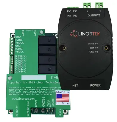 For Fargo G2, Koda
TCP/IP Web Op relais gebaseerde controller
Herz. C 04/2022
Fargo G2 TCP/IP Web Op relais gebaseerde controller
Thank you for purchasing a Linortek Fargo G2 or Koda TCP/IP Controller. There are many devices that can be controlled by the FARGO/KODA Web Relay Controller. FARGO/KODA Web Controller can be used in such applications as (but not limited to): Lights, security, sprinkler systems, access control, industrial equipment, building automation, HVAC, and many more. Please refer to the Board Reference Layouts on page 29 for input and output specifications on your controller to verify they are suitable to your needs.
Deze handleiding behandelt:
- FARGO R8 G2
- FARGO R4DI G2
- FARGO R4ADI G2
- KODA 100
- KODA200
These will be referred to as SERVER hereafter. When there are differences or additional features they will be noted in the text.
Ga voor instructievideo's, veelgestelde vragen en contactgegevens van ons technische ondersteuningsteam naar: https://www.linortek.com/technical-support
LINORTEK EEN JAAR BEPERKTE GARANTIE
Consumer law: For consumers who are covered by consumer protection laws or regulations in their country of residence (“Consumer Law”), the benefits provided in this Linortek One-Year Limited Warranty (“Linortek Limited Warranty”) are in addition to and not instead of the rights provided by Consumer Law and it does not exclude, limit or suspend your rights arising from Consumer Law. You should consult the proper authorities in your country of residence for further information about these rights
De garantieverplichtingen van Linortek voor dit hardwareproduct (“Product”) zijn beperkt tot de onderstaande voorwaarden:
Linor Technology, Inc. (“Linortek”) warrants this product against defects in materials and workmanship for a period of ONE (1) YEAR from the date of retail purchase by the original end-user purchaser (“Warranty Period”) when used in accordance with the operating instructions. A copy of a retail receipt is required as proof of purchase. If a hardware defect arises and a valid claim is received within the Warranty Period, at its option and to the extent permitted by law, Linortek will either (1) repair the hardware defect at no charge, using new or refurbished replacement parts, (2) exchange the product with a product that is new or which has been manufactured from new or serviceable used parts and is at least functionally equivalent to the original product, or (3) refund the purchase price of the product. When a refund is given, the product for which the refund is provided must be returned to Linortek and becomes Linortek’s property.
De voorgaande garantie is afhankelijk van de (i) onmiddellijke schriftelijke claim van de Koper en (ii) het tijdig verstrekken aan Linortek van de gelegenheid om het Product dat beweerdelijk defect te zijn, te inspecteren en testen. Een dergelijke inspectie kan plaatsvinden op het terrein van de Koper en/of Linortek kan verzoeken om retournering van het Product op kosten van de Koper. Linortek is echter niet verantwoordelijk voor verpakkings-, inspectie- of arbeidskosten in verband met het retourneren van het Product. Geen enkel product wordt geaccepteerd voor garantieservice als het niet vergezeld gaat van een Return Merchandise Authorization Number (RMA#), uitgegeven door Linortek.
UITSLUITINGEN EN BEPERKINGEN
Deze beperkte garantie sluit schade uit die voortvloeit uit misbruik, verkeerd gebruik, verwaarlozing, brand of andere externe oorzaken, ongelukken, wijzigingen, reparaties of andere oorzaken die geen materiaal- en fabricagefouten zijn. Software die door Linortek wordt gedistribueerd met of zonder de merknaam Linortek, inclusief maar niet beperkt tot systeemsoftware (“Software”), wordt niet gedekt door deze Beperkte Garantie. Uw gebruik en rechten in verband met de Software worden beheerst door de Linortek Eindgebruikerslicentieovereenkomst, die u hier kunt vinden: https://www.linortek.com/end-user-licenseagreement/. Linortek is niet verantwoordelijk voor schade die voortvloeit uit het niet opvolgen van instructies met betrekking tot het gebruik van het product. Om conformiteit met de gebruiksbeperkingen te verzekeren, dient de koper de instructiehandleiding [meegeleverd met het product] te raadplegen. Batterijen zijn niet inbegrepen in de garantie.
VOOR ZOVER MAXIMAAL TOEGESTAAN, ZIJN DEZE BEPERKTE GARANTIE EN DE HIERBOVEN VERMELDE VERHAALSMOGELIJKHEDEN EXCLUSIEF EN TER PLAATS VAN ALLE ANDERE GARANTIES, VERHAALSMOGELIJKHEDEN EN VOORWAARDEN, EN LINORTEK WIJST SPECIFIEK ALLE WETTELIJKE OF IMPLICIETE GARANTIES AF, INCLUSIEF MAAR NIET BEPERKT TOT GARANTIES VAN VERKOOPBAARHEID, GESCHIKTHEID VOOR EEN BEPAALD DOEL, NIET-INBREUK. VOOR ZOVER DERGELIJKE GARANTIES NIET KUNNEN WORDEN AFGEWEZEN, ZULLEN AL DERGELIJKE GARANTIES, VOOR ZOVER TOEGESTAAN DOOR DE WET, IN DUUR BEPERKT TOT DE DUUR VAN DE BEPERKTE GARANTIE VAN LINORTEK EN ZAL DE REMEMIE BEPERKT ZIJN TOT REPARATIE, VERVANGING OF TERUGBETALING ZOALS BEPAALD DOOR LINORTEK NAAR EIGEN GOEDDUNKEN. SOMMIGE STATEN (LANDEN EN PROVINCIES) STAAN GEEN BEPERKINGEN TOE MET BETREKKING TOT HOE LANG EEN IMPLICIETE GARANTIE OF VOORWAARDE KAN GAAN, DUS DE HIERBOVEN BESCHREVEN BEPERKINGEN ZIJN MOGELIJK NIET OP U VAN TOEPASSING. DEZE GARANTIE GEEFT U SPECIFIEKE WETTELIJKE RECHTEN, EN U KUNT OOK ANDERE RECHTEN HEBBEN DIE VAN STAAT TOT STAAT (OF PER LAND OF PROVINCIE) VERSCHILLEN. DEZE BEPERKTE GARANTIE WORDT BEHEERD EN GEÏNTEGREERD ONDER DE WETTEN VAN DE VERENIGDE STATEN.
Vrijwaring
- Lees de instructies – Lees alle veiligheids- en bedieningsinstructies voordat u het product in gebruik neemt.
- Bewaar instructies – Bewaar de veiligheids- en bedieningsinstructies voor toekomstig gebruik.
- Let op waarschuwingen – Houd u aan alle waarschuwingen op het product en in de gebruiksaanwijzing.
- Volg de instructies – Volg alle bedienings- en gebruiksinstructies.
- Reiniging – Haal de stekker van het product uit het stopcontact voordat u het schoonmaakt. Gebruik geen vloeibare reinigingsmiddelen of spuitbussen. Gebruik advertentieamp doek alleen voor het reinigen van de behuizing.
- Bijlagen – Gebruik geen bijlagen tenzij deze specifiek worden aanbevolen door Linortek. Het gebruik van incompatibele of anderszins ongeschikte hulpstukken kan gevaarlijk zijn.
- Accessoires – Plaats dit product niet op een onstabiele standaard, statief, beugel of steun. Het product kan vallen, met ernstig persoonlijk letsel en ernstige schade aan het product tot gevolg. Gebruik alleen met een standaard, statief, beugel of montage die wordt aanbevolen door de fabrikant of wordt verkocht met het product. Volg de instructies van de fabrikant bij het monteren van het product en gebruik alleen door de fabrikant aanbevolen montageaccessoires. Wees voorzichtig bij het gebruik van een combinatie van apparaat en kar. Snel stoppen, overmatige kracht en oneffen oppervlakken kunnen ervoor zorgen dat de combinatie van het apparaat en de kar omvalt.
- Ventilatie – openingen in de behuizing, indien aanwezig, zijn voorzien voor ventilatie en om een betrouwbare werking van het product te garanderen en om het te beschermen tegen oververhitting. Blokkeer of bedek deze openingen niet. Plaats dit product niet in een ingebouwde installatie, tenzij voor voldoende ventilatie is gezorgd of de instructies van Linortek zijn opgevolgd.
- Stroombronnen – Gebruik dit product alleen met het type stroombron dat wordt aangegeven in de handleiding of op het productlabel.
Als u niet zeker weet welk type stroomvoorziening u van plan bent te gebruiken, raadpleeg dan uw apparaatdealer of het plaatselijke energiebedrijf – op voorwaarde dat het gebruik van een ander type stroombron dan aangegeven in de gebruiksaanwijzing of het markeringslabel elke garantie ongeldig maakt. Voor producten die bedoeld zijn om op batterijvoeding of andere bronnen te werken, raadpleegt u de gebruiksaanwijzing [meegeleverd met het product]. - Aarding of polarisatie – Dit product kan zijn uitgerust met een gepolariseerde wisselstroomlijnstekker (een stekker waarvan het ene blad breder is dan het andere). Deze stekker past maar op één manier in het stopcontact. Dit is een veiligheidsvoorziening. Als u de stekker niet volledig in het stopcontact kunt steken, probeer dan de stekker om te draaien. Als de stekker nog steeds niet past, komt dat omdat uw stopcontact niet compatibel is met de stekker. Neem contact op met uw elektricien om uw stopcontact te vervangen door een geschikt stopcontact. Forceer de stekker niet om in een incompatibel stopcontact te passen of probeer op een andere manier het veiligheidsdoel van de stekker te omzeilen. Dit product kan ook zijn uitgerust met een 3-draads aardingsstekker, een stekker met een derde (aardings)pin. Deze stekker past alleen in een geaard stopcontact. Dit is een veiligheidsvoorziening. Forceer de stekker niet om in een incompatibel stopcontact te passen of probeer op een andere manier het veiligheidsdoel van de stekker te omzeilen. Als uw stopcontact niet compatibel is met de stekker, neem dan contact op met uw elektricien om uw stopcontact te vervangen door een compatibel exemplaar.
- Bescherming van het netsnoer – Leg de voedingssnoeren zo neer dat er niet op kan worden gelopen of dat ze niet kunnen worden afgekneld door voorwerpen die erop of ertegenaan worden geplaatst, met bijzondere aandacht voor snoeren en stekkers, stopcontacten en het punt waar de snoeren uit het apparaat komen .
- Elektriciteitskabels – Plaats een buitensysteem nergens in de buurt van bovengrondse hoogspanningslijnen of andere elektrische licht- of stroomcircuits, of waar het in dergelijke hoogspanningslijnen of circuits kan vallen. Wanneer u een buitensysteem installeert, wees dan uiterst voorzichtig om te voorkomen dat u dergelijke elektriciteitsleidingen of circuits aanraakt, aangezien contact ermee fataal kan zijn.
- Overbelasting – Overbelast de stopcontacten en verlengsnoeren niet, omdat dit brand of elektrische schokken kan veroorzaken.
- Binnendringen van voorwerpen en vloeistoffen – Duw nooit voorwerpen van welke aard dan ook door openingen in dit product, omdat ze gevaarlijke vloeistoffen kunnen raken.tage punten of kortgesloten onderdelen die brand of elektrische schokken kunnen veroorzaken. Mors nooit vloeistof van welke aard dan ook op het product.
- Onderhoud – Probeer niet zelf onderhoud aan dit product uit te voeren, aangezien het openen of verwijderen van afdekkingen u kan blootstellen aan gevaarlijke voltage of andere gevaren. Laat al het onderhoud aan het product over aan Linortek.
- Schade waarvoor service nodig is – Haal de stekker van het product uit het stopcontact en raadpleeg de Linortek-klantenondersteuning onder de volgende omstandigheden:
A. Als het netsnoer of de stekker beschadigd is.
B. Als er vloeistof is gemorst of als er voorwerpen op het product zijn gevallen.
c. Als het product is blootgesteld aan regen of water.
D. Als het product niet normaal werkt door de gebruiksaanwijzingen te volgen [meegeleverd met het product]. Pas alleen de bedieningselementen aan die in de bedieningsinstructies worden beschreven, aangezien een onjuiste afstelling van andere bedieningselementen tot schade kan leiden en vaak uitgebreid werk van een gekwalificeerde technicus vereist om het product weer normaal te laten werken.
e. Als het product is gevallen of de behuizing is beschadigd.
F. Als het product een duidelijke verandering in prestatie vertoont. - Vervangende onderdelen – Als vervangende onderdelen nodig zijn, zorg dan voor een Low-Voltage Elektricien vervang ze door alleen een door de fabrikant gespecificeerd onderdeel te gebruiken. Ongeautoriseerde vervangingen kunnen leiden tot brand, elektrische schokken of andere gevaren. Vervangende onderdelen zijn te vinden op: https://www.linortek.com/store/
- Veiligheidscontrole – Vraag de servicetechnicus om na voltooiing van service of reparaties aan dit product veiligheidscontroles uit te voeren om vast te stellen dat het product in goede staat verkeert.
- Coax-aarding – Als er een extern kabelsysteem op het product is aangesloten, zorg er dan voor dat het kabelsysteem is geaard. Alleen modellen voor de VS – sectie 810 van de National Electrical Code, ANSI/NFPA No.70-1981, geeft informatie over de juiste aarding van de steun en ondersteunende structuur, aarding van de coax naar een ontladingsproduct, grootte van aardgeleiders, locatie van het ontladingsproduct, aansluiting op aardelektroden en vereisten voor de aardelektrode.
- Bliksem – Voor extra bescherming van dit product tijdens onweer of voordat u het voor langere tijd onbeheerd en ongebruikt achterlaat, trekt u de stekker uit het stopcontact en koppelt u het kabelsysteem los. Dit voorkomt schade aan het product door blikseminslag en stroompieken.
- Buitengebruik – Dit product is niet waterdicht en mag niet nat worden. Niet blootstellen aan regen of andere soorten vloeistoffen.
Laat het apparaat niet 's nachts buiten staan, omdat er condensatie kan optreden. - Let bij het vervangen van batterijen, zekeringen of het hanteren van een board-level product op voor elektrostatische ontlading die elektronische apparaten kan beschadigen. U kunt het beste een geaarde elektronicaservicebank gebruiken. Als dit niet aanwezig is, kunt u zich ontladen door een metalen apparaat of pijp aan te raken. Raak tijdens het vervangen van de batterijen of zekeringen i) geen andere draden aan dan de batterijdraden en ii) de printplaat.
BEPERKING VAN AANSPRAKELIJKHEID
IN NO EVENT WILL LINOR TECHNOLOGY BE LIABLE, WHETHER IN CONTRACT, TORT, OR OTHERWISE, FOR ANY INCIDENTAL, SPECIAL, INDIRECT, CONSEQUENTIAL OR PUNITIVE DAMAGES, INCLUDING, BUT NOT LIMITED TO, DAMAGES FOR ANY LOSS OF USE, LOSS OF TIME, INCONVENIENCE, COMMERCIAL LOSS, OR LOST PROFITS, SAVINGS, OR REVENUES TO THE FULL EXTENT SUCH MAY BE DISCLAIMED BY LAW. DISCLAIMER FOR CRITICAL APPLICATIONS
Dit product is niet bedoeld of geautoriseerd voor levensondersteunende producten of voor ander gebruik waarbij een storing persoonlijk letsel of de dood kan veroorzaken. Als u of uw klanten dit product voor dergelijk onbedoeld of ongeoorloofd gebruik gebruiken of toestaan, gaat u ermee akkoord Linor Technology en haar dochterondernemingen, en de functionarissen, werknemers en distributeurs van elk, volledig te vrijwaren van alle aansprakelijkheid met betrekking tot dergelijk gebruik, inclusief honoraria en kosten van advocaten.
VERDERE KENNISGEVING VOOR BEPERKING VAN GEBRUIK
Tenzij specifiek vermeld, zijn onze producten NIET ontworpen om lijnvolume te wisselentage (110V en hoger) apparaten. Om apparaten te bedienen die werken op lijn voltagEen gekwalificeerde elektricien MOET een tussenapparaat installeren, zoals een relais. Bij het kiezen van apparaten om te bedienen, is het het beste om laag vol . te selecterentage-bedieningselementen zoals een 24VAC-solenoïde naar waterstroomregeling. Alleen gekwalificeerde elektriciens mogen een lijn voltage-apparaat. Bovendien moeten de lokale codes worden gevolgd, inclusief maar niet beperkt tot de draaddikte en geschikte behuizing. Linortek aanvaardt geen verantwoordelijkheid voor schade aan de gebruiker of derden als gevolg van onjuist gebruik van onze producten. Deze aansprakelijkheid blijft bij de gebruiker. Linortek aanvaardt geen verantwoordelijkheid voor schade aan het apparaat als gevolg van onjuist gebruik van onze producten.
RELAIS VOLTAGE SPECIFICATIES
Wees voorzichtig bij het aansluiten van apparaten op elektrische circuits of andere apparatuur. Dit web controller is NIET ontworpen om verbinding te maken met een voltage greater than 48V. Utilizing this arrangement, should allow you to virtually control anything. It is important that you use licensed electricians and comply with electrical codes that are applicable to your location. These codes exist for your safety, as well as the safety of others. Linortek assumes no responsibility for any harm or damage resulting from a failure adhere to local laws, ordinances or regulations or failure to follow specified instructions for installation and product usage.
Licentieovereenkomst voor eindgebruikers voor Linortek-software en documentatie
Deze licentieovereenkomst voor eindgebruikers (“EULA”) is een wettelijke overeenkomst tussen U (een individu of enkele entiteit) en Linor Technology, Inc. (“Linortek” of “wij” of “ons”) die uw gebruik van de software regelt en documentatie (“Software”) ingebed in of geassocieerd met de Fargo-, Koda-, Netbell-, IoTMeter- en iTrixx-productreeksen (“Linortek-producten”).
Deze EULA is niet van toepassing op uw gebruik van de Linortek webwebsite of de Linortek-producten (exclusief de Software). Uw gebruik van de Linortek website wordt beheerd door de Linortek webservicevoorwaarden van de site en het privacybeleid van Linortek, te vinden op:
http://www.linortek.com/terms-and-conditions [Uw aankoop van Linortek-producten (exclusief de software) valt onder de beperkte garantie van Linortek, die u kunt vinden op https://www.linortek.com/linortek-one-year-limited-warranty/
This EULA governs your access and use of the Software. This EULA gives you specific legal rights, and you may also have other legal rights in addition, which vary from jurisdiction to jurisdiction. The disclaimers, exclusions, and limitations of liability under
this EULA will not apply to the extent prohibited or limited by applicable law. Some jurisdictions do not allow the exclusion of implied warranties or the exclusion or limitation of incidental or consequential damages or other rights, so those provisions of this EULA may not apply to you.
Door de Software of documentatie te installeren, te openen, te kopiëren en/of te gebruiken, gaat u ermee akkoord gebonden te zijn aan de bepalingen en voorwaarden van deze EULA namens uzelf of de entiteit die u vertegenwoordigt in verband met dergelijke installatie, toegang, kopiëren en/of gebruik. U verklaart en garandeert dat (i) u het recht, de autoriteit en de capaciteit heeft om de voorwaarden van deze EULA te accepteren en ermee akkoord te gaan namens uzelf of de entiteit die u vertegenwoordigt (ii) u de wettelijke leeftijd heeft bereikt in het rechtsgebied waar u woont , (iii) u bevindt zich niet in een land dat onderworpen is aan een embargo van de Amerikaanse regering, of dat door de Amerikaanse regering is aangewezen als een land dat terrorisme ondersteunt; en (ii) u niet vermeld staat op een lijst van de Amerikaanse overheid met verboden of beperkte partijen.
Als u niet gebonden wilt zijn aan de voorwaarden van deze EULA, mag u de Software op geen enkele manier installeren, openen, kopiëren of gebruiken (al dan niet vooraf geïnstalleerd op een apparaat dat u hebt aangeschaft).
- Toegestaan gebruik van software/softwarelicentie.
Met inachtneming van de voorwaarden van deze EULA, verleent Linortek u een beperkt, herroepbaar, niet-exclusief, niet-sublicentieerbaar, niet-overdraagbaar recht en licentie om (a) één exemplaar van de Software te downloaden, installeren en uitvoeren, in uitvoerbare objectcodevorm alleen, uitsluitend op het Linortek-product dat u bezit of beheert en om (b) de Software uitsluitend te gebruiken in verband met het Linortek-product in overeenstemming met het beoogde gebruik zoals beschreven op de Linortek website (elk van 1(a) en 1(b) een "Toegestaan gebruik" en gezamenlijk "Toegestaan gebruik"). - Beperkingen op uw gebruik van de software.
U stemt ermee in de Software niet te gebruiken, en anderen ook niet toe te staan, de Software te gebruiken voor enig ander doel dan het Toegestane gebruik zoals beschreven in Sectie 1 hierboven. Dit betekent onder meer dat u niet:
(a) enig deel van de Software bewerken, wijzigen, wijzigen, aanpassen, vertalen, er afgeleide werken van maken, demonteren, reverse-engineeren of reverse compileren (behalve voor zover toepasselijke wetgeving dergelijke beperkingen specifiek verbiedt voor interoperabiliteitsdoeleinden, in welk geval u ermee akkoord gaat om eerst contact op te nemen met Linortek en Linortek de kans te geven de wijzigingen door te voeren die nodig zijn voor interoperabiliteitsdoeleinden);
(b) de Software in licentie geven, toewijzen, distribueren, verzenden, verkopen, verhuren, hosten, uitbesteden, openbaar maken of anderszins gebruiken voor commerciële doeleinden of de Software beschikbaar stellen aan derden;
(c) toestaan dat een derde partij de Software gebruikt namens of ten behoeve van een derde partij;
(d) enig deel van de Software gebruiken op een ander apparaat of computer dan het Linortek-product dat u bezit of beheert;
(e) de Software gebruiken op een manier die in strijd is met toepasselijk lokaal, nationaal of internationaal recht; of
(f) remove or alter any labels, symbols, legends or proprietary notices, including but not limited to any copyright, trademark, logo in the Software. You may not disclose the results of any performance or functional evaluation of anyof the Software to any third party without the prior written consent of Linortek for each such release. - Updates.
Linortek kan van tijd tot tijd updates, upgrades, patches, bugfixes en andere aanpassingen (“Updates”) ontwikkelen om de prestaties van de Software te verbeteren. Tenzij anders vermeld op de Linortek website, worden deze Updates gratis aan u verstrekt. Deze updates kunnen automatisch worden geïnstalleerd zonder u hiervan op de hoogte te stellen. Door de Software te gebruiken, stemt u ook in met automatische Updates. Als u hier niet mee instemt, mag u de Software op geen enkele manier installeren, openen, kopiëren of gebruiken. - Eigendom.
The Software is licensed to you and not sold. Linortek reserves all rights to the Software and any Updates not expressly granted herein. The Software and Linortek Products are protected by copyright, trademark and other intellectual property laws andtreaties. Linortek and its licensors own the title, copyright, trademarks and other intellectual property rights in the Software.
You are not granted any rights to Linortek’s trademarks or service marks. There are no implied licenses in this EULA. - Beëindiging.
This EULA is effective from the date you first use the Software and will continue for as long as you own the Linortek Product associated with it or until you or Linortek terminate this agreement under this section. You may terminate this EULA at any time upon written notice to Linortek at the address provided below. Linortek may terminate this EULA at any time if you fail to comply with any of the terms in this agreement. The license granted in this EULA terminates immediately when the agreement terminates. Upon termination, you must stop using the Linortek Product and the Software and you must delete all copies of the
Software. The terms of Sections 2 will still remain in effect after the agreement terminates. - Garantieverklaring.
EXTENT PERMITTED BY APPLICABLE LAW, LINORTEK PROVIDES THE SOFTWARE “AS-IS” AND DISCLAIMS ALL WARRANTIES AND CONDITIONS, WHETHER EXPRESS, IMPLIED, OR STATUTORY, INCLUDING THE WARRANTIES OF MERCHANTABILITY, FITNESS FOR A PARTICULAR PURPOSE, TITLE, QUIET ENJOYMENT, ACCURACY, AND NON-INFRINGEMENT OF THIRD-PARTY RIGHTS. LINORTEK DOES NOT GUARANTEE ANY SPECIFIC RESULTS FROM THE USE OF THE SOFTWARE. LINORTEK MAKES NO WARRANTY THAT THE SOFTWARE WILL BE UNINTERRUPTED, FREE OF VIRUSES OR OTHER HARMFUL CODE, TIMELY, SECURE, OR ERROR-FREE. YOU USE THE SOFTWARE AND THE LINORTEK PRODUCT AT YOUR OWN DISCRETION AND RISK. YOU WILL BE SOLELY RESPONSIBLE FOR (AND LINORTEK DISCLAIMS) ANY AND ALL LOSS, LIABILITY, OR DAMAGES RESULTING FROM YOUR USE OF THE SOFTWARE
AND LINORTEK PRODUCT. - Beperking van aansprakelijkheid.
Niets in deze EULA en in het bijzonder in deze clausule "Beperking van aansprakelijkheid" zal proberen aansprakelijkheid uit te sluiten die niet kan worden uitgesloten onder de toepasselijke wetgeving.
VOOR ZOVER MAXIMAAL TOEGESTAAN DOOR DE TOEPASSELIJKE WETGEVING, IN AANVULLING OP DE BOVENSTAANDE AFWIJZINGEN VAN GARANTIE, ZAL (A) LINORTEK IN GEEN GEVAL AANSPRAKELIJK ZIJN VOOR ENIGE GEVOLG, VOORBEELDIGE, SPECIALE OF INCIDENTELE SCHADE, MET INBEGRIP VAN VERLOREN SCHADE VAN OF MET BETREKKING TOT DE PRODUCTEN OF SOFTWARE, ZELFS ALS LINORTEK DE MOGELIJKHEID VAN DERGELIJKE SCHADE WIST OF MOET HEBBEN, EN (B) DE TOTALE CUMULATIEVE AANSPRAKELIJKHEID VAN LINORTEK VOORTVLOEIEND UIT OF VERBAND MET DE PRODUCTEN EN HET SOFTWARE OF HET CONTRACT OF DAARNA ZAL BEPERKT WORDEN TOT EEN BEDRAG DAT NOOIT HET BEDRAG OVERSCHRIJDT DAT WERKELIJK DOOR U BETAALD IS AAN LINORTEK EN DE GEAUTORISEERDE DISTRIBUTEUR OF VERKOOPVERTEGENWOORDIGER VAN LINORTEK VOOR DE PRODUCTEN OF DIENSTEN DIE IN DE VOORAFGAANDE 6 MAANDEN (INDIEN AANWEZIG) ZIJN. DEZE BEPERKING IS CUMULATIEF EN ZAL NIET WORDEN VERHOOGD BIJ HET BESTAAN VAN MEER DAN ÉÉN INCIDENT OF CLAIM. LINORTEK WIJST ALLE AANSPRAKELIJKHEID VAN ENIGE SOORT LICENTIEGEVERS EN LEVERANCIERS VAN LINORTEK AF. - Naleving van exportwetten.
U erkent dat de Software en gerelateerde technologie onderworpen zijn aan de Amerikaanse exportcontrolewetten, de Amerikaanse exportjurisdictie en mogelijk onderworpen zijn aan export- of importregels in andere landen. U stemt ermee in om alle toepasselijke internationale en nationale wet- en regelgeving die van toepassing is op de Software strikt na te leven, inclusief de Amerikaanse Export Administration Regulations en beperkingen voor eindgebruikers, eindgebruik en bestemming die zijn uitgevaardigd door Amerikaanse en andere overheden. U erkent dat u de verantwoordelijkheid heeft om toestemming te verkrijgen voor het exporteren, herexporteren of importeren van de Software en gerelateerde technologie, indien nodig.
U zult Linortek vrijwaren van alle claims, verliezen, aansprakelijkheden, schadevergoedingen, boetes, sancties, kosten en uitgaven (inclusief advocatenhonoraria) die voortvloeien uit of verband houden met enige schending door u van uw verplichtingen onder deze sectie. - Opdracht.
U mag geen van uw rechten of verplichtingen onder deze EULA overdragen, en elke poging tot overdracht is nietig en heeft geen effect. - Mededelingen.
Linortek kan alle kennisgevingen met betrekking tot deze EULA aan u verstrekken met behulp van het e-mailadres en adres dat u hebt opgegeven toen u zich bij Linortek registreerde. - Vrijstelling
Om effectief te zijn, moeten alle afstandsverklaringen door Linortek hieronder schriftelijk zijn en ondertekend door een geautoriseerde Linortek-vertegenwoordiger. Elk ander falen van Linortek om enige voorwaarde hieronder af te dwingen, wordt niet als een verklaring van afstand beschouwd. - Deelbaarheid.
Elke bepaling van deze EULA die niet-afdwingbaar wordt bevonden, zal worden bewerkt en geïnterpreteerd om de doelstellingen van die bepaling zo goed mogelijk te bereiken volgens de toepasselijke wetgeving en alle overige bepalingen blijven volledig van kracht. - Toepasselijk recht; Locatie.
You agree that this EULA, and any claim, dispute, action, cause of action, issue, or request for relief arising out of or relating to this EULA, will be governed by the laws of the state of North Carolina, U.S.A., without regard to conflicts of laws principles, provided that if you reside in a country that will not apply U.S. law to disputes related to these terms, then the laws of your country will apply. You also agree that the United Nations Convention on Contracts for the International Sale of Goods shall not
apply. You agree that regardless of any statute or law to the contrary, any cause of action against us arising out of or related to the Linortek website, de Software of de Linortek-producten moeten beginnen binnen één (1) jaar nadat de oorzaak van de actie is ontstaan, anders wordt een dergelijke actie permanent uitgesloten. Elke actie of procedure met betrekking tot deze EULA moet worden voorgelegd aan een federale of staatsrechtbank in Raleigh, North Carolina en elke partij onderwerpt zich onherroepelijk aan de jurisdictie en locatie van een dergelijke rechtbank in een dergelijke claim of geschil, behalve dat Linortek een verbod kan vorderen schadevergoeding in een rechtbank die jurisdictie heeft om zijn intellectuele eigendom te beschermen. - Californië Voorstel 65 Waarschuwing.
 WAARSCHUWING: Dit product kan u blootstellen aan chemicaliën, waaronder lood, waarvan in de staat Californië bekend is dat het kanker veroorzaakt. Ga voor meer informatie naar www.P65Warnings.ca.gov.
Aan de slag
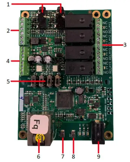
The Fargo SERVER is what is called a “bare board” product and is supplied without a housing. It operates on low voltage; however you need to use simple handling precautions to prevent damage to the circuits. All electronics are susceptible to electrostatic discharge. This high voltage “shock” can permanently damage your device. Before handling the product, you should touch a surface such as a grounded workbench or table. It is also best to handle the device from its edges. If you notice that your chair or clothes often cause static discharges, you must exercise extra caution. The unit is supplied with four rubber feet which keeps the bottom of the board from coming into contact with the surface you put it on. Be careful not to let metal objects, such as screw drivers or hardware, come in contact with the bottom of this product. The board can be mounted on a panel using stand offs and #4 hardware. The mounting holes are connected to the GROUND signal. The SERVER unit is a self-contained web server configured with various input and output circuits. Although the relays are rated for higher voltages, dit product is niet ontworpen voor gebruik bij lijnvoltages. You should never use voltages through the SERVER product exceeding 48 volts. IT IS NOT SAFE.
The KODA SERVER is a housed unit with a DIN rail mountable enclosure that can be snapped onto a DIN rail or attached to any flat surface such as a wall or under a counter. KODA 100 has two relays (48VAC@1A), KODA 200 has four relays which can drive 10V 50mA to external devices. The unit is supplied with a DIN Rail mountable enclosure with removable terminal connectors for easy installation. The KODA SERVER can be mounted on a panel or on the wall using the DIN rail mount clip. The removable wire terminal connectors simplify field installation and allow for easy troubleshooting and maintenance: the unit can be removed from the system without disturbing the system wiring.
De server bedraden
Opmerking: For a diagram showing the location of all connectors on your SERVER referenced in this section, please see the section – Board Layout Reference.
Voorzichtigheid: Deze units zijn geïsoleerd op de grond. Sluit altijd zo aan dat de voedingslus alleen op de SERVER-eenheid is aangesloten.
Gebruik GEEN externe aardaansluitingen. Als u dit wel doet, kan het SERVER- of POE-apparaat beschadigd raken.
- Place the unit on a table or bench being careful not to let any metal objects come into contact with the bottom of the circuit board (Fargo Only).
- Connect the 12VDC power supply to a suitable AC outlet and plug the barrel connector into the SERVER at the location labelled “12VDC/POWER”. Alternatively, you may also use POE. At this point the GREEN/Boot LED should come on and start flashing indicating the SERVER is operating and is in the “Bootload Mode”. This mode allows the user to update the server software that is used on the unit. After about 5 seconds, the GREEN LED will go off and the RED LED will start blinking once per second indicating the SERVER is operating in “Server Mode” and is accessible on a network utilizing TCP/IP protocols.
VOORZICHTIGHEID: WANNEER U DE POE-NETWERKSCHAKELAAR GEBRUIKT, GEBRUIK DE 12VDC-VOEDING NIET OM DE SERVER TEGELIJKERTIJD UIT TE VOEREN, DIT ZAL DE BOARD BESCHADIGEN. - Plug an Ethernet cable into the RJ45/NET connector. The “Connection” LED will come on if a 100MHz network is available, otherwise it will remain off and the “Activity” LED should start blinking indicating network activity. Fargo G2 Relay Connections
There are 8 relays on the FARGO R8 and 4 on the FARGO R4. These are dry contact relays. These units are designed for only low voltage-controle en mag geen voltage applied to the relay greater than 48 volts. This is for your safety as well as to stay within the parameters of the parts and circuit board design. The relays have 3 terminals labelled NO, C and NC which stand for Normally Open, Common and Normally Closed. When activated, the relay moves the connection from CNC to CNO. If you want to make a connection when the relay is activated, connect your wires between C and NO. When the relay is activated C and NO will be connected together. If you want to break a circuit when the relay is activated, make your connections to C and NC. When the relay is activated the circuit will be broken (or open)
Koda Relay Connection
There are 2 relays on the KODA 100. The KODA 100 has 2 removable 2 position connectors (1 for each relay) and are simply numbered “1” and “2”. These relays are normally open.
There are 4 relays on the KODA 200. The KODA 200 has 1 removable 8 position connector. Each relay has a “+” connection and a numbered connection. The relays may be set to supply about 10VDC by selecting “+V” on the setting switch (see Board Layout Reference page 29) or set to dry contact DC on the switch. If “+V” is selected then the voltage will be present on the “+” terminal and the numbered terminal is the return. Otherwise, a normally open dry contact exists across the “+” and numbered connection. KODA 100/200 is designed for only low voltage-controle en mag geen voltage toegepast op het relais van meer dan 48 volt. Dit is voor uw veiligheid en om binnen de parameters van de onderdelen en het printplaatontwerp te blijven.

![]() IN GEEN GEVAL ZAL LINOR TECHNOLOGY AANSPRAKELIJK ZIJN, IN CONTRACT, ONRECHTMATIGE OF ANDERSZINS, VOOR ENIGE INCIDENTELE, SPECIALE, INDIRECTE, GEVOLGSCHADE OF STRAFSCHADE, MET INBEGRIP VAN, MAAR NIET BEPERKT TOT, SCHADE VOOR ENIG TIJDVERLIES, , COMMERCIEEL VERLIES OF VERLIES VAN WINST, BESPARINGEN OF INKOMSTEN, VOOR ZOVER DEZE WETTELIJK KUNNEN WORDEN AFGEWEZEN.
IN GEEN GEVAL ZAL LINOR TECHNOLOGY AANSPRAKELIJK ZIJN, IN CONTRACT, ONRECHTMATIGE OF ANDERSZINS, VOOR ENIGE INCIDENTELE, SPECIALE, INDIRECTE, GEVOLGSCHADE OF STRAFSCHADE, MET INBEGRIP VAN, MAAR NIET BEPERKT TOT, SCHADE VOOR ENIG TIJDVERLIES, , COMMERCIEEL VERLIES OF VERLIES VAN WINST, BESPARINGEN OF INKOMSTEN, VOOR ZOVER DEZE WETTELIJK KUNNEN WORDEN AFGEWEZEN.
VERDERE KENNISGEVING VOOR BEPERKING VAN GEBRUIK
Tenzij specifiek vermeld, is dit product NIET ontworpen om van lijn te wisselentage apparaten. Deze beperking geldt voor alle FARGO- EN KODA-producten. Om apparaten te bedienen die werken op lijnvoltages de gebruiker MOET een tussenapparaat zoals een relais installeren.
Bij het bedraden van een lijn voltagAls het apparaat een tussenapparaat gebruikt, MOET u een gekwalificeerde elektricien zijn of gebruik maken van de diensten van een gekwalificeerde elektricien. Bovendien moeten lokale voorschriften worden gevolgd, inclusief, maar niet beperkt tot, de maat van de draaddikte en een geschikte behuizing.
Linortek cannot assume any responsibility for harm to the user or third parties for improperly using our Fargo/Koda products. This liability remains with the user. Linortek cannot assume any responsibility for damage to the device for improperly using our SERVER product.
For relay specifications, please see Board Reference Layout page 29
Digital Input Connections (Fargo R4 and Koda)
The digital inputs allow the SERVER to detect an external on/off state of a sensor. With this information the SERVER can display whether an input is on or off, count events in a resettable or non-resettable counter, and calculate the frequency (such as for use as a tachometer) or the period of the input. There are two modes of operation for the digital inputs – PULL UP and ISOLATED.
a) PULL UP mode connects a 1K resistor to an internal voltage waardoor u een eenvoudige schakelaar (zoals een magnetische deurschakelaar) kunt gebruiken tussen klem 1 en 2. Wanneer de schakelaar wordt geactiveerd, wordt er een signaal naar de ingang gestuurd.
b) ISOLATED mode allows you to directly drive the SERVER’s optoisolator with an external voltage door een interne 1K-weerstand. deze voltagDe spanning kan in het bereik liggen van 5 V tot 24 V en levert minimaal 2 mA of maximaal 30 mA aan de opto-isolatordiode. Er is geen andere interne verbinding met dit deeltage so it is an isolated input. Please note, when connecting a 12VDC-¬24VDC circuit to the input, an external resistor (can be provided at request, 2.2k ohm 0.5watt) must be used.
These modes are selected by the switch on the SERVER (see Board Layout Reference page 29) marked ISO and PU for isolated and pull up respectively. These are set at the factory to ISO by default.
Wiring a push button: For distances up to 500 feet, a 20 AWG shielded wire is suitable for wiring a push button. If the distance between the push button and the controller extends up to 5,000 feet, use a 16 AWG shielded cable instead. Keep in mind that longer cable runs are more susceptible to signal interference.
Voorzichtigheid: If you intend to use isolated mode, verify that the input switch is set to ISO before applying an external voltage. Anders kan het SERVER- of POE-apparaat beschadigd raken.
Analog Input Connections (Fargo R4ADI)
The analog inputs allow the SERVER to read the value of external equipment. There are 2 analog inputs.
For AC current monitoring, use one of the two 3.5mm stereo inputs to interface with a current sensor.
De 2 analoge ingangsklemmenblokken zijn verbonden met niet-geïsoleerde 0-5V-stroomsensoren die kunnen worden aangesloten op een verscheidenheid aan apparaten, zoals temperatuur- of druksensoren. De SERVER biedt een aard- en stroomaansluiting zodat metingen kunnen worden uitgevoerd zonder externe voltage references. You should use a sensor that is isolated so that that it makes no connection to a remote ground. See drawing under Board Reference Layout page 29.
Accessing your SERVER
Zodra uw SERVER is ingeschakeld en met het netwerk is verbonden, verkrijgt deze automatisch een IP-adres via DHCP, zolang uw router hiervoor is geconfigureerd. Om verbinding te maken, voert u het IP-adres in uw web browser. This will take you to your SERVER’s landing page. To log in, click the Log In button on the top right of the page. Your browser will prompt you to enter your username and password. By default, these credentials are both set to admin. To find your SERVER’s IP address, see below.
Uw IP-adres vinden met Linortek Discoverer
Het Discoverer-programma zal uw SERVER automatisch lokaliseren. De Discoverer is een Java-programma en vereist dat Java Runtime is geïnstalleerd om deze functie te kunnen gebruiken. Java is hier te vinden: http://java.com/en/download/index.jsp.
Om het Discover-programma te downloaden, gaat u naar: https://www.linortek.com/downloads/supportprogramming/
Het gebruik van Chrome- en Firefox-browsers wordt aanbevolen. Let op: als u liever Internet Explorer gebruikt, slaat Internet Explorer Linortek Discoverer op als een Zip file standaard. Om de Discoverer te gebruiken, moet u Opslaan als selecteren en de naam van de file als Linortek Discoverer.jar wanneer u downloadt.
Wanneer u het Discover-programma downloadt, ziet u soms een pop-upwaarschuwingsbericht, afhankelijk van de beveiligingsinstellingen van uw browser, met de vraag of u dit bestand wilt behouden of verwijderen. file, please click the Keep button as this is a Java program, and it won’t harm your computer.
Zodra Discoverer uw apparaat heeft gevonden, wordt het volgende weergegeven:
- IP-adres
- Hostnaam
- MAC-adres
- Overige info:
A. Blauwe LED (indien aan)
B. productnaam
C. Serversoftwarerevisie
D. Poortnummer (indien geporteerd)

Klik op het apparaat dat u wilt gebruiken, weergegeven in het Discoverer-programma, om de SERVER te starten web pages in your browser. Click the Login button on the homepage. The default username/password is: admin/admin. You may change these as you desire or disable this feature in the settings menu.
Connecting your SERVER Directly to Your PC
You can also plug your SERVER directly to your PC if there is no network connection available. If you plug your SERVER into your PC’s Ethernet port it will use the default IP address: 169.254.1.1 unless you have previously configured your SERVER to use a static IP. Enter 169.254.1.1 into your web browser to connect. No internet connection is required. Once configured, you can then install your SERVER where you desired.
Serverconfiguratie
Inloggen
Once you have entered the IP address and port number, if set, the Login page will open. This page shows the name of this server which you may change in Configure/Network Config.
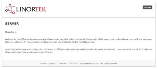
This page is static with no background activity and is a useful place to park if you are not using the SERVER and do not want to close the connection.
By pressing LOGIN, you will be asked for your username and password. These credentials will be retained by the browser until the browser is closed. You can disable the password requirement in Settings page. See section page 21.
Startpagina
Zodra uw inloggegevens zijn ingevoerd, wordt u doorgestuurd naar de hoofdpagina van de applicatie. De Home- of Index-pagina geeft een deel van de systeeminformatie weer en biedt de mogelijkheid om het fysieke apparaat te lokaliseren als het zich in een gebied met anderen bevindt. Zie onderstaande lijst voor een beschrijving.

- TIME – Displayed along with the day of the week. This time may be set to be in a 12 hour format with AM/PM indicator or 24 hour format.
- DATUM – De huidige datum wordt hier weergegeven.
- VOLTS – Voltage op het bord wordt weergegeven. Dit kan handig zijn als de SERVER samen met andere apparatuur van stroom wordt voorzien, voltage variance can be noted. Fargo and Koda servers have an input voltage range of 1248vDC.
- TEMPERATURE – Temperature on the board is displayed. This display may be either °C or °F. This temperature will be affected by the heat generated by SERVER itself so it will always be slightly higher than ambient temperature.
- LED's – Er worden 3 LED's weergegeven. De RODE LED is de systeempuls. Dit zou ongeveer één keer per seconde moeten knipperen zolang de server actief is. De GROENE LED wordt gebruikt voor bootloader-opties en is over het algemeen niet zichtbaar op de webplaats. De BLAUWE LED is klikbaar en kunt u hiervandaan aan- en uitzetten web bladzijde. Dit is handig om het apparaat fysiek te lokaliseren als het in gebruik is met andere soortgelijke apparaten, aangezien het gaat branden op de eenheid waarop dit apparaat is aangesloten. web browser is verbonden. Het Discoverer-programma merkt ook of de BLAUWE LED brandt. Dit wordt vaak een “Locate”-functie genoemd.
Diensten
Het tabblad Services is dynamisch en verandert afhankelijk van de configuratie van uw server. Hier kunt u de ingangen, uitgangen, sensoren en andere speciale bedieningselementen bedienen.
In/Out or Relays Page
Depending on which SERVER you are using, the first page on the SERVICES tab will be either In/Out or Relays.
In/Out has the relay controls and the input controls on one page, while Relays only has the relay controls.
Relaisbesturing
An In/Out page is displayed below. Some relay control pages have 2, 4 or 8 relays displayed. Each relay has a number, in this case 1 to 4.

The State LED shows whether the relay is on or off indicated by GREEN and RED respectively. This icon is clickable to manually control the corresponding relay. Each relay can have a Name as well as identifiers for the Normally Open, Common and Normally Closed connections.
Er zijn vier status-LED's die het volgende weergeven:
- Email – If an email is to be sent when this relay is switched on/off
- Puls – Als dit relais is ingesteld met een pulsbreedte en pulsbreedtevermenigvuldiger (duur) – zie het volgende gedeelte voor meer informatie
- Sched. – If there is a schedule created in the Tasks page (see page 15) set to automatically trigger this relay.
- Getimed – Als er een puls is ingesteld en dit relais is geactiveerd, wordt de getimede LED rood, wat aangeeft dat het relais momenteel op een timer werkt.
Click the Edit Icon to edit the controls for the corresponding relay. This will take you to the Set Relay page (see page 11).
Ingangen
The In/Out or Inputs page (depending on your SERVER) will display information from each input. The SERVERs have a combination of inputs. The Fargo R4DI has four digital inputs, The R4ADI has, four digital inputs, four analog inputs. The KODA SERVER has two digital inputs.
At the top of each input is a label (ex: DIN 1, AIN 2) specifying whether it is a digital input (DIN) or analog input (AIN) as well as the input number. This label will turn green when the input is enabled. Inside the box will be any display configured from the Set Input page (see page 12 for digital input, page 14 for analog input). A red dot in the lower-left corner indicating the state of a linked relay (if any), will turn green when the linked relay is activated.
Finally, an Edit icon in the lower-right corner of the box to edit the corresponding input. This will take you to the Set Digital Input or Set Analog Input page (page 12 or page 14).
Set Relay Page
Op de pagina SET RELAY kunt u verschillende eigenschappen met betrekking tot het relais instellen.
- Relay Select – The Relay that you are editing (identified by the line on which you clicked the Edit icon on the RELAY page).
- Name – Enter a 15-character Relay Name. This and the following 3 fields may be used for any identifying information desired.
- NO Name – Enter a 7-character name for the Normally Open (NO) connection.
- Com Name – Enter a 7-character name for the Common (COM) connection.
- NC Name – Enter a 7-character name for the Normally Closed (NC) connection.
- Pulse Width – When you control the relay it turns on or off. You may control it for a timed turned on period by entering a Pulse Width when 0 means there is no timed event and a number represents duration of the pulse. The maximum number you can enter here is 4 digits, ie. 1234.
- Pulsbreedtevermenigvuldiger – Om de pulslengte verder te definiëren, selecteert u een Pulsbreedtevermenigvuldiger om de pulsbreedte verder te definiëren. U kunt selecteren:
• Geen
• mS (Millisecond, 1/1000 second)
• Sec (Seconds)
• Min (Minutes) - Relay Type – de SERVER heeft fysiek toegang tot relais op de SERVER of op andere manieren. U kunt selecteren:
• Normal – relay physically on the SERVER
• Latched – not currently supported
• Remote – a relay on another SERVER accessed over the network
• Zigbee – a relay at a remote device accessed over an RF system
• Normal and Remote – both relays activated
• Normal and Zigbee – both relays activated - Locatie-ID – dit is een nummer dat een externe locatie identificeert
- Relay op locatie – een nummer dat het relais of apparaat op de locatie vertegenwoordigt
- E-mail verzenden – de SERVER kan worden geprogrammeerd om een e-mail te verzenden als het relais is in- of uitgeschakeld.

Digitale invoerpagina instellen
De digitale ingangen kunnen worden ingesteld om verschillende uitlezingen te bieden bij gebruik van een reeks displaytypen. Naast het weergeven van de invoergegevens kunt u het display een naam geven en er een relais aan koppelen. Dit relais verandert van groen naar ROOD als het van aan naar uit gaat en is klikbaar om het te bedienen. Door op het potloodpictogram bewerken te klikken, kunt u de instellingen voor deze invoer bewerken:
- Digital Input Selected – The Digital Input that you are editing (identified by the line on which you clicked the Edit icon).
- Naam – U kunt voor deze ingang een naam van 15 tekens instellen. Deze naam komt in de balk bovenaan het scherm te staan.
- Label – Stel een label van 7 tekens in dat wordt weergegeven op het daadwerkelijke actieve display.
- Corrector – Met dit veld kunt u een waarde optellen, aftrekken, vermenigvuldigen of delen voordat de waarde op de weergavepagina wordt weergegeven. Dit is een corrector voor 2 waarden, waarbij elke waarde wordt gescheiden door één spatie. (dat wil zeggen: “+2, -2, *3, /3”)
- GEBRUIK – Zet deze ingang op actief. Zet de invoernummerindicator op groen. Opgemerkt moet worden dat de invoer tijdens gebruik CPU-tijd en andere bronnen verbruikt, afhankelijk van het type. Hoewel alle ingangen tegelijkertijd actief kunnen zijn, is het raadzaam alleen de ingangen in te schakelen die u wilt gebruiken.
- Type – De invoergegevens kunnen worden gebruikt om een reeks resultaten te berekenen. U kunt selecteren:
• State – This is useful for knowing if an input is on or off, like a door switch being on or off.
• CounterNR – This is a non-resettable counter.
• CounterR – This is a resettable counter.
• Frequency – Counts the frequency of an input in KHz (kilo hertz or1/1000 seconds). This could be useful in displaying a tachometer where 60Hz = 1 R.P.M.
• Period – in 1/1000 seconds an input in kHz (milliseconds or1/1000 seconds). This would be useful for measuring timed events. - Weergave – Met deze selectie kunt u het gebruikte weergavetype wijzigen. U kunt selecteren:
• Dot – A single dot with the value in the middle. This can be used for State. You can make a dumb indicator by changing the color of the Dot based on the value. The label is under the Dot.
• Values – Displays the Corrected Value with the Label in a box directly below it.
• Meter – This Meter has configurable scale based on the Min/Max values and arcs can be colored per the Color ranges. The Label is displayed within the Meter.
• VBar – Also based on the Min/Max values for the scale and the bar changes color based on the values in the Color ranges. - Relay L/T – Enter a Relay number here. If it is a local relay it will show GREEN or RED depending if it is on or off. By clicking on it the relay will turn on and off. The name comes from the relay settings page. This may be useful if you want to turn the subject of a display on and off. Any relay can be used on any input and each may be reused for any other input. Adding an L after the relay number (ex: 2L) will link the state of the input to the state of the relay. This is an easy and immediate way to have an input follow the relay. Adding a T after the relay number will trigger the relay to the state of the input. This is an easy and immediate way to have a relay follow the input.
- Command Z/N/I – This field is used for issuing various commands to the Digital Input controller: Z Zero the resettable counter. N Leave the input as Normal. I Invert the input.
- Value – These are Min/Max values used for the display. This is useful for preventing a Meter from going past its end or setting the value of a VBar. This is the Value after the Corrector. The system cannot display a value past Max, so be sure this is at least set to 1.
- Geel/Rood/Groen – Er zijn drie kleuren die kunnen worden gebruikt om een display verder te definiëren. Stel het bereik van deze kleuren in om een kleur te definiëren voor de weergavewaarde. Dit is de waarde na de Corrector. Houd er rekening mee dat als u een statustype gebruikt, u wellicht ROOD = Van 0 naar 0, GROEN = Van 1 naar 1 en GEEL = Van 2 naar 2 wilt toewijzen. Omdat een status altijd 1 of 0 is, voorkomt dit dubbelzinnige informatie en voorkomen dat de GELE kleur wordt gebruikt. U kunt twee kleuren selecteren die u leuk vindt voor een staatstype.

Set Analog Input Page
De analoge ingangen kunnen worden ingesteld om verschillende uitlezingen te bieden bij gebruik van een reeks displaytypen. Naast het weergeven van de invoergegevens kunt u het display een naam geven en er een relais aan koppelen. Dit relais verandert van groen naar ROOD als het van aan naar uit gaat en is klikbaar om het te bedienen.
- Analog Input Selected – The Analog Input that you are editing (identified by the line on which you clicked the Edit icon).
- Naam – U kunt voor deze ingang een naam van 15 tekens instellen. Deze naam komt in de balk bovenaan het scherm te staan.
- Label – Stel een label van 7 tekens in dat wordt weergegeven op het daadwerkelijke actieve display.
- Corrector – Met dit veld kunt u een waarde optellen, aftrekken, vermenigvuldigen of delen voordat de waarde op de weergavepagina wordt weergegeven. Dit is een corrector voor 2 waarden, waarbij elke waarde wordt gescheiden door één spatie. (dat wil zeggen: “+2, -2, *3, /3”)
- USE – Sets this input to active. Turns the input number indicator to GREEN. It should be noted that when in use the input consumes CPU time and other resources depending on its type. Although all inputs may be active at the same time, it is recommended to turn on only those you want to use.
- Type – De invoergegevens kunnen worden gebruikt om een reeks resultaten te berekenen. U kunt selecteren:
• Analog 1 – Analog 1 input from a SERVER with an input such as found on a R4ADI.
• Analog 2 – Analog 2 input from a SERVER with an input such as found on a R4ADI.
• AC Current 1 – AC current sensor 1 input from a SERVER with an input such as found on a R4ADI.
• AC Current 2 – AC current sensor 2 input from a SERVER with an input such as found on a R4ADI.
• AC Current 3 – Not used
• Volts – The measurement of the voltage powering the SERVER.
• Current – On “S” models, this is the current consumed by the SERVER.
• Int. Temp – Temperature from the board mounted sensor.
• Ext. Temp – Temperature from the “S” model SERVER.
• R. Humidity – % Relative Humidity from the “S” model SERVER.
• MMA X – The X axis accelerometer data from the “S” model SERVER.
• MMA Y – The Y axis accelerometer data from the “S” model SERVER.
• MMA Z – The Z axis accelerometer data from the “S” model SERVER. - Weergave – Met deze selectie kunt u het gebruikte weergavetype wijzigen. U kunt selecteren:
1. Dot – A single dot with the value in the middle. This can be used for State. You can make a dumb indicator by changing the color of the Dot based on the value. The label is under the Dot.
2. Values – Displays the Corrected Value with the Label in a box directly below it.
3. Meter – This Meter has configurable scale based on the Min/Max values and arcs can be colored per the Color ranges. The Label is displayed within the Meter.
4. VBar – Also based on the Min/Max values for the scale and the bar changes color based on the values in the Color ranges. - Relay – Enter a Relay number here. If it is a local relay it will show Green or RED depending if it is on or off.
By clicking on it the relay will turn on and off. The name comes from the relay settings page. This may be useful if you want to turn the subject of a display on and off. Any relay can be used on any input and each may be reused for any other input. - Waarde – Dit zijn Min/Max-waarden die voor de weergave worden gebruikt. Dit is handig om te voorkomen dat een meter over het einde gaat of om de waarde van een VBar in te stellen. Dit is de waarde na de Corrector. Het systeem kan geen waarde voorbij Max weergeven, dus zorg ervoor dat deze minimaal op 1 staat.
- Geel/Rood/Groen – Er zijn drie kleuren die kunnen worden gebruikt om een display verder te definiëren. Stel het bereik van deze kleuren in om een kleur te definiëren voor de weergavewaarde. Dit is de waarde na de Corrector. Houd er rekening mee dat als u een statustype gebruikt, u wellicht ROOD = Van 0 naar 0, GROEN = Van 1 naar 1 en GEEL = Van 2 naar 2 wilt toewijzen. Omdat een status altijd 1 of 0 is, voorkomt dit dubbelzinnige informatie en voorkomen dat de GELE kleur wordt gebruikt. U kunt twee kleuren selecteren die u leuk vindt voor een staatstype.

Tasks Page
The TASKS page displays the automatic events that can be programmed into the SERVER. You can schedule up to 16 events in the SERVER. These are constructed as IF … THEN statements. In addition, the IF term can have 2 elements (IF a, AND/OR/NOT b … THEN c). This provides a simple to program and powerful way to take advantage of the data acquired by the SERVER. The Tasks page shows you an overview of configured tasks. You can click the dot in the State column to turn a task on or off indicated by a green dot for ON, and a red dot for OFF. To edit or create a task, click the Edit icon to the right of the task line. This will take you to the Set Schedule page detailed in the next section.

Set Schedule Page
The SET SCHEDULE page allows you to create time and logic-based events that will occur automatically if the conditions are met.
- Schedule Select – Determined by clicking on a schedule line from the previous page.
- Schedule Name – Enter a 15-character Schedule Name.
- USE – In order for a Schedule line to be active you must select the USE button. If there is an error detected in entering Schedule data, the USE box will automatically uncheck.
- LOG – Selecteer log zodat dit item elke keer dat het wordt uitgevoerd in het systeemlogboek verschijnt.
- Email – Click Email to automatically send an email when this schedule is executed.
- Device A – Select Device A for the first term in the IF statement from the drop box.
- Data A – Select Data A for the above device. Depending on the device selected, the Data used for testing may have special properties. See the list below for Data that may be entered. If an error is detected indata entry when the “Save” button is pushed, the USE box will uncheck and the Data box containing the error will be highlighted.
• Minute – Enter: mm
• Hour – Enter: hh (use 24-hour system)
• Day – Enter: dd
• DayofWeek – Enter: Sunday = 1, Monday = 2, Tuesday = 3, Wednesday = 4, Thursday = 5, Friday = 6, Saturday = 7, Weekday = 8, Weekend = 9
• Time – Enter: hh:mm (use leading zeros, seconds are ignored) (use 24 hour system) ex:07:30 or 14:05
• Date – Enter: yy/mm/dd (use leading zeros) ex: 20/01/10 for January 10, 2020
• Relay – Enter: Relay number and (+ or -), ex: 01+ for Relay 1 ON or 01- for Relay 1 OFF
• Button – Enter: + or – (for ON or OFF respectively)
• Flag – Enter: Flag number(opt.+), or Flag number (for ON or OFF respectively)
• Temp – Enter: >, = or < value; example: >40 (altijd graden C)
• Volts – Enter: >, = or < value; exampnl: <10
• Analog – Analog input. Enter an input number and >, = or < and value. Example: 3<123 (This value is raw data value prior to any Corrector used by the input display page.)
• Digital – Digital input. Enter Input Number, Type, >, =, or < and value; example: 1F>7500 (This value is the raw data value prior to any Corrector used on the display page). Type can be (case sensitive):
• S State (On/Off)
• C Non-resettable counter
• c Resettable counter (lower case ‘c’)
• F Frequency in 1/1000 seconds
• P Period in 1/1000 seconds - Logica – Stel een logische vergelijking in tussen apparaat A en apparaat B.
• AND – True if: Device A is true AND Device B is true
• OR – True if: Device A is true OR Device B is true
• NOT – True if: Device A is true and Device B is NOT true - Device B – Select Device B for testing from the drop box.
- Data B – Selecteer Data B voor het bovenstaande apparaat. Afhankelijk van het geselecteerde apparaat kunnen de voor het testen gebruikte gegevens speciale eigenschappen hebben. Zie bovenstaande lijst.
- Apparaat C – is wat u moet besturen.
- Data C – Eigenschap instellen voor apparaat C. De syntaxis wordt als volgt gebruikt:
• RELAY – These are relays on this SERVER. You can set up to four per schedule. Enter separated by commas, for exampde “1,2,3,4”
• FLAG – This is a storage flag that can be used to make more complex schedules. There are 8 flags that can be turned on or off.
• REMOTE – Refers to a remote SERVER unit. When these conditions are met, this SERVER will send a command to control a remote SERVER. The Data field for a remote unit should be in the format,
“REMOTE UNIT NUMBER, REMOTE UNIT RELAY”. For example, “3,5”. Deze externe SERVERS moeten worden geïdentificeerd op de pagina Configure/Remote Device Config.
• COUNTER – Adds count to digital input counter – set as 1 or 2 depending on which digital input is counting
• BLUE LED – No data.
• eMAIL – Will send eMail, no data.
• NOTIFY – Will send notification to Kodalert, set 1- 8 for Settings/Alarm Notification number. (Not Implemented) - Actie – Wat te doen met apparaat C. Opties zijn:
• ON – Turns device ON
• OFF – Turns device OFF
• TGL – Toggles state of Device C
• RESET – Resets CounterR

Logs-pagina
The Logs tab displays over 10,000 entries from actions taken by the SERVER or by users themselves. This feature allows several actions for the convenience of displaying and collecting data from the SERVER.
- The checkboxes above the date allow the user to filter logs from different sources. To filter out logs you do not wish to see from a certain source simply uncheck the box.
- Each log has a reference number and a time and date attached in a “yyyy/mm/dd” and “hh:mm:ss” format. Afterwards is the event displayed.
- To scroll through the logs, use the arrows to the right-hand side, where the horizonal line and arrow brings you to the start or end, the double arrow moves up or down a page, and the single arrow moves up or down a single log.
- To refresh the logs manually click the REFRESH button below the Log Details.
- To download the Log Details, click the DOWNLOAD button below the Log Details, this allows you to save the logs as a separate file.
Pagina met gebruikers- en beheerdersreferenties
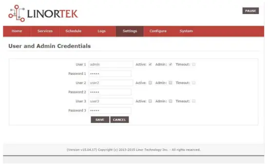
Use this page from the Settings drop down menu. Here you can set up to 3 users for your SERVER system. As a default only User 1 is Active. Here you can:
- User Name and Password – Each user has their own credentials. As a default these are set toadmin/admin, user2/user2 and user3/user3 for Users 1, 2 and 3 respectively. The passwords are never displayed. Opmerking: when you reset the password, it must be less than 13-character.
- Actief – Moet worden aangevinkt voordat deze gebruiker zich kan aanmelden. U kunt Gebruiker 1 niet deactiveren.
- Beheerder – Alleen de beheerder kan gegevens op de meeste pagina’s opslaan. Dit beschermt uw SERVER tegen wijzigingen door een onbevoegde persoon.
- Time-out – Momenteel niet ingeschakeld.
Pagina Tijd/Datum
Gebruik deze pagina via het vervolgkeuzemenu Instellingen. Op deze pagina kunt u het tijd- en datumsysteem instellen.
- Time – Set time using an hh:mm:ss format.
- Datum – Stel de datum in met behulp van het jj/mm/dd-formaat.
- Time Zone – Set desired time zone 5 for EST, 8 for PST, you can now add a :mm for setting part hour, for example, 5:30 is een tijdzone van 5 uur en 30 minuten.
- Zomertijd gebruiken – Selecteer deze optie om uw systeemtijd automatisch aan te passen op de zomerdag. (Niet nauwkeurig in alle tijdzones.)
- Gebruik MIL-tijd – Selecteer om de 24-uursnotatie te gebruiken.
- Use NTP Update – Select to synchronize SERVER time with NTP server
- NTP Web Site – Dit is de geselecteerde NTP-server voor updates.
- NTP-interval – Tijdsinterval tussen updates in minuten.
- Log NTP Event – Normally NTP exceptions will be logged, select this option to Log every NTP event. (May be useful in debugging.)

Instellingenpagina
Access this page from the Settings dropdown menu. Select these settings to enable various features in the SERVER
- Use Active Main – No longer used. (Select PAUSE to go inactive.)
- Inloggen vereisen – Als dit niet is geselecteerd, staat de SERVER alle toegang toe zonder inloggegevens.
- Use IP Ranges – Not Implemented.
- Use RESTFUL IP Ranges – Not implemented.
- Use Remote IP Ranges – Not implemented.
- Gebruik RESTful Authenticatie – Vereist gebruikersnaam en wachtwoord voor RESTful.
- Vergroot het relaisbereik – Schakelt 8 relais in.
- Gebruik relaiskeuzerondjes – Indien ingesteld: als één relais wordt ingeschakeld, worden alle andere uitgeschakeld.
- SSL Port No. – Not supported – For future use.
- Systeem-e-mails gebruiken – Schakelt aanvullende e-mailberichten in.
- Fahrenheit gebruiken – Selecteer Celsius of Fahrenheit.
- PGM Dynamic Relays – Changes properties of relays in task schedule.
- CLR PGMs on Start – Reinitialize tasks on start up.
- RTC Temperature Compensation – All Koda boards can add Temperature and Humidity sensor.
- Gebruik AM2302 – Gebruik AM2302 temperatuur- en vochtigheidssensor (apart verkrijgbaar).
- Java Report – Send data to HourCollector app over ethernet (only for IoTMeter)
- Use Metric – Not supported – For future use.
- UART Usage – Enter “Audio” for Netbell-NTG, “Clock” for Netbell clock.
- Switch Bypass (1/2) – Ignores physical inputs if set. For example, in a Koda 200 board, you want to ignore input 1 switch, check Switch Bypass 1
- Setting 19 – Not supported – For future use
- Audio gebruiken File System – Activate SD Card reader for Netbell-NTG
- WiFi Report – Enable data transfer over WiFi (WiFi IoTMeter only)
- Active Landing Page – Not supported – For future use.
- . Invert Relay Control – The relay is set to NO by default. By checking this box the relay will be inverted to NC.
- Setting 24 – Not supported – For future use.

Dynamische DNS-pagina
Access this page from the Configure dropdown menu. From this page you can assign dynamic DNS settings. This page, along with proper port forwarding through the router, can enable global access to a device behind a NAT router or firewall. You will need to assign a static IP address and port number (see Network Config Page on page 25) and port the IP address on your router (refer to your router’s user manual). An internet IP address will have to be hosted in order to access your SERVER from the internet. Currently the only IP hosting service supported is provided by DynDNS (https://dyn.com)
- Gebruik DDNS – Schakelt deze service in.
- DDNS-service – Selecteer een service in de vervolgkeuzelijst. Momenteel is DynDNS de enige ondersteunde service
- Gebruikersnaam – Dit verwijst naar het account dat is ingesteld bij de DDNS-service.
- Wachtwoord – Wachtwoord voor toegang tot de DDNS-service.
- Host – This is the IP name registered at the DDNS service for rerouting to this SERVER

E-mailconfiguratiepagina
Stel een e-mailaccount in die de SERVER kan gebruiken bij het verzenden van e-mailberichten vanuit verschillende modules. Open deze pagina via het tabblad Configureren.
Opmerking: This unit is NOT compatible with SSL/TLS, there are 3rd party SMTP delivery servers which do not require SSL and can be used. For instructions on how to use a 3rd party SMTP delivery service, please refer to Appendix 1 at the end of this manual).
- SMTP-server – Voer de uitgaande mailserver in die u wilt gebruiken.
- Poort – Dit is de poort op die server. U kunt uw e-mailservice online opzoeken voor deze informatie, evenals voor de andere instelvelden.
- Gebruik SSL – Laat dit uitgeschakeld als u een SMTP-server van derden gebruikt.
- Gebruikersnaam – Uw e-mailaccountnaam.
- Wachtwoord – Wachtwoord voor e-mailaccount.
- To Address – Enter up to 3 address for this email set up. An addressee, a CC and a BC.
- Onderwerp – Onderwerpregel van de e-mailheader.

Netwerkconfiguratiepagina
Access this page from the Configure dropdown menu. This page allows the configuration of the SERVER’s network settings.
VOORZICHTIGHEID: Incorrect settings may cause the board to lose network connectivity. In order to access a device in your network remotely you must PORT the device. This tells your router that information coming in should be sent to a specific device on your network.
- MAC Address – This is a unique MAC address that is assigned to this product at time of assembly. It cannot be altered.
- Hostnaam – Dit is een Netbios-naam waarmee deze unit in sommige netwerken kan worden aangesproken. Het kan ook in de leasedirectory van uw router voorkomen. Het is een handige plek om uw SERVER een naam te geven en het verschijnt op de startpagina en op de Discoverer.
- Port Number – Dit wordt onderdeel van het IP-adres en is nodig voor internettoegang. Als dit niet is ingesteld, wordt de SERVER standaard ingesteld op poortnummer 80.
- IP Address – Typically you only change the last group of numbers. If you change this IP address make sure to reserve this IP on your router and no other devices are using this IP address or you may not be able to reach this SERVER. If this happens you may need to Restore Defaults using the push button method.
- Gateway – Meestal een router op uw TCP/IP-netwerk die dient als toegangspunt voor uw ISP.
- Subnet Mask – Een 32-bits nummer dat een IP-adres maskeert en het IP-adres verdeelt in netwerkadres en hostadres. Laat het gewoon op 255.255.255.0 staan
- Primaire DNS – Een primaire DNS.
- Secundaire DNS – Een secundaire DNS.

Configuratiepagina IP-bereik
Access this page from the Configure dropdown menu. Use these security settings to select a range of IP address that will be allowed to access the SERVER.CAUTION: Incorrect settings may cause the board to lose network connectivity. Not implemented on this SERVER.
Pagina Externe apparaten
Access this page from the Configure dropdown menu. These settings allow the SERVER to remotely control the relays on another SERVER. This is done by selecting the Remote Device in the Schedule program or by setting up a relay as a REMOTE. There are 8 possible REMOTE locations.
VOORZICHTIGHEID: Onjuiste instellingen zorgen ervoor dat het bord zijn externe verbindingen verliest.
- Apparaatnaam – Voer een tekstnaam in voor dit apparaat voor toekomstig gebruik.
- IP-adres – Het IP-adres van het externe apparaat, inclusief een poortnummer.
- Gebruikersnaam – Gebruikt bij basisauthenticatie.
- Password – Used in Basic Authentication.

Kodalert Page
Not Yet Implemented. Access this page from the Configure dropdown menu. Kodalert provides an interface for alerts of Internet connected devices. Kodalert is a cloud based, open platform monitoring and alert system for the Internet of Things in your physical world. Any Thing that can send an email or TCP messages including our SERVERS, other manufactures devices and people using email can use Kodalert. It can work for multiple remote locations, alert multiple users instantly using the rules you setup by text, email, smart phone Apps push notification or audible alarm instantly when something happens.
- Waarschuwingsnummer
- Test
- Gebruik
- Regel
In the Alarm Notification page, you can change the state (on/off) of the relay by clicking the green circle in the state column. Push the EDIT icon to change the Alarm’s settings.

Specificaties
FARGO R8G2
- 10M/100M RJ45 Internet interface with connection and activity LEDs
- 8 Relay outputs, 1FORMC 48 Volt Max (24VAC/DC 3A)
- Status LEDs (pulse, bootloader, and locate)
- Ethernet Bootloader (for server hardware code upgrade)
- PoE or 12VDC @500mA (nominal)
- Web interface w/basic authentication
- On board temperature sensor and voltagde sensor
Reset /Locate pushbutton (blue LED) - Working Temperature from 0 to +70 Celsius
- Storage Temperature from 40 to +125 Celsius
- Humidity from 10% to 80% noncondensing
- Dimensions 74mm x 100mm x 20mm, mounting holes 64mm x 92mm Ф 3.2mm 4 places
- Ondersteunde protocollen: HTTP/SMTP/SNTP
FARGO R4G2
- 10M/100M RJ45 Internet interface with connection and activity LEDs
- 4 1FormC relays 48 Volt Max (24VAC/DC 3A)
- 2 optically isolated digital inputs, 12V 1mA or pulldown switch selectable, 2 conductor screw terminal connectors for each.
- 2 Analog 0-5VDC Inputs 30mA 3.3VDC power source PTC protected. 3 conductor screw terminal connectors for each (3.3VDC, input, ground) (R4ADI only)
- 2 Current sensor inputs. 3.5mm stereo jack connector for each (R4ADI only)
- Status LEDs (pulse, bootloader, and locate)
- Ethernet Bootloader (for server hardware code upgrade
- POE or 12VDC @500mA (nominal)
- Web interface w/basic authentication
- On board temperature sensor and voltagde sensor
- Reset/Locate pushbutton
- Working Temperature from 0 to +70 Celsius
- Storage Temperature from 40 to +125 Celsius
- Humidity from 10% to 80% noncondensing
- Dimensions 74mm x 100mm x 20mm, mounting holes 64mm x 92mm Ф 3.2mm 4 places
- Ondersteunde protocollen: HTTP/SMTP/SNTP
KODA100
- 10M/100M RJ45 Internet interface with connection and activity LEDs
- 2 1-Form-A relay 48VAC@8A Max
- 2 optically isolated digital inputs, 12V 1mA or pulldown switch selectable
- Status LEDs (pulse, bootloader, and locate)
- Ethernet Bootloader (for server hardware code upgrade)
- POE or 12VDC @500mA (nominal)
- Web interface w/basic authentication
- On board temperature sensor and voltagde sensor
- Reset/Locate pushbutton (blue LED)
- Working temperature from 0 to +70 Celsius
- Storage temperature from 40 to +125 Celsius
- Humidity from 10% to 80% noncondensing
- Afmetingen: 70mm x 100mm x 25mm
- Ondersteunde protocollen: HTTP/SMTP/SNTP
KOD200
- 10M/100M RJ45 Internet interface with connection and activity LEDs
- 4 1FormA relays 48 Volt Max 1A dry contact or drive 10V ±10% 50mA to external devices
- 2 optically isolated digital inputs, 12V 1mA or pulldown switch selectable
- Status LEDs (pulse, bootloader, and locate)
- Ethernet Bootloader (for server hardware code upgrade)
- POE or 12VDC @500mA (nominal)
- Web interface w/basic authentication
- On board temperature sensor and voltagde sensor
- Reset/Locate pushbutton (blue LED)
- Working Temperature from 0 to +70 Celsius
- Storage Temperature from 40 to +125 Celsius
- Humidity from 10% to 80% noncondensing
- Afmetingen: 70mm x 100mm x 25mm
- Ondersteunde protocollen: HTTP/SMTP/SNTP
Bordreferentie-indeling
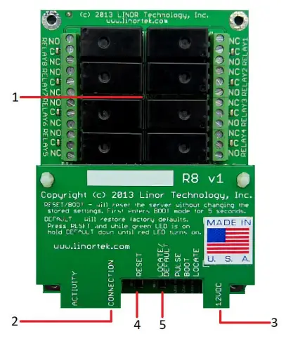
Fargo R8
- 8 Relay outputs, 1FORMC 48 Volt Max (24VAC/DC 3A)
- Rj45-connector
- Voedingsconnector (12VDC)
- Resetknop
- Lokaliseerknop
Fargo R4
- 3.5mm Inputs for AC Current Sensor (R4ADI Only)
- Analog Inputs (R4ADI Only)
- 4 Relay outputs, 1FORMC 48 Volt Max (24VAC/DC 3A)
- Digitale ingangen
- Digital Input Switches (Input 1 on right.
Up: Pullup, Down: Isolated) - Rj45-connector
- Resetknop
- Lokaliseerknop
- Voedingsconnector (12VDC)
Koda 100
- Digital Inputs (#1 on the left) 5VDC-48VDC (12VDC-48VDC must use the external resistor)
- Relay Outputs (#1 is on the right) 8A@48VAC Max
- Digital Input Switches (IN 1 on left. UP: Isolated, Down: Pullup)
- Resetknop
- Herlaadknop (schakelt blauwe LED in – identificeert op Discoverer)
- Rj45-connector
- Voedingsconnector (12VDC)
- USB-miniconnector voor temperatuur-/vochtigheidssensor (apart verkrijgbaar)

Koda 200
- Digital Inputs (#1 on the left) 5VDC-48VDC (12VDC-48VDC must use the external resistor)
- Relay Outputs (#1 is on left) 48 Volt Max 1A dry contact or drive 10V ±10% 50mA
- Digital Input Switches (IN 1 on left. UP: Isolated, Down: Pullup)
- Relay Switches (Up for dry contact, down for 10V/50mA)
- Resetknop
- Herlaadknop (schakelt blauwe LED in – identificeert op Discoverer)
- Rj45-connector
- Voedingsconnector (12VDC)
- USB-miniconnector voor temperatuur-/vochtigheidssensor (apart verkrijgbaar)

Fabrieksinstellingen herstellen
To perform a factory Reset, push the Reset button. When the green LED turns on, push and hold the Reload button until the flashing red LED turns off and then turns on solid. Refer to Board Reference Layout section for the button locations on your device.
This user-manual supplements the documentation for the following Linortek products:
- Netbell-2
- Netbell-8
- Netbell-K (and variants)
- iTrixx-NHM
For more information, documentation and how-to videos, visit https://www.linortek.com/downloads/
Dit document is te vinden op: www.linortek.com/downloads/documentations/
Als u hulp nodig heeft met uw apparaat, gaat u naar www.linortek.com/technische ondersteuning
Linor Technologie, Inc.
Informatie kan zonder voorafgaande kennisgeving worden gewijzigd.
Bijlage 1
SSL-e-mails verzenden met behulp van een SMTP-service van derden voor Linortek Fargo- en Koda-apparaten
Standaard gebruiken Koda/Fargo-apparaten niet-SSL SMTP-e-mailservers. Maar de meeste e-mailservers zijn tegenwoordig overgestapt op het SSL-beveiligingsprotocol. Er zijn SMTP-bezorgservers van derden die geen SSL vereisen en kunnen worden gebruikt. Er zijn veel SMTP-e-mailserviceproviders op de markt. Wij gebruiken SMTP3GO als example om het installatieproces te demonstreren. SMTP2GO is gratis te gebruiken met maximaal 1000 e-mails/maand. Om SMTP2GO te gebruiken, ga naar: https://www.smtp2go.com/ .
Stap 1. Maak het SMTP2GO-account aan.
Om een account aan te maken, klikt u eenvoudigweg op ‘Aanmelden’, kiest u ‘1K E-mails’ op de schaal en kiest u ‘Gratis abonnement’ (als u meer dan 1000 e-mails per maand moet verzenden, selecteert u het abonnement dat aan uw vereisten voldoet.)

Om een account op SMTP2GO aan te maken, is een zakelijk e-mailadres nodig. Met gratis e-maildiensten zoals Gmail of Yahoo kunt u niet verder. Nadat u uw SMTP2GO-account heeft geactiveerd, moet u een gebruiker toevoegen.
Stap 2. Voeg een gebruiker toe.
De gebruiker die u op SMTP2GO aanmaakt, zal de server voor uitgaande e-mail zijn wanneer u het Fargo/Koda-apparaat instelt om e-mailrapporten te verzenden. Zorg ervoor dat de e-mailserver van uw bedrijf de e-mails niet blokkeert als u een gratis e-mailaccount zoals Yahoo of Gmail gebruikt om voeg hier een gebruiker toe.
Log in op uw SMTP2GO-account, kies in het menu aan de linkerkant “Instellingen” > “SMTP-gebruikers”, klik op “SMTP-gebruiker toevoegen” en vul het formulier in.
 Nadat de gebruiker aan uw SMTP2GO-account is toegevoegd, wordt de informatie weergegeven die u nodig hebt om de e-mailmelding op uw Fargo/Koda-apparaten in te stellen.

Stap 3. Configureer het Linortek-apparaat.
Nadat u een account hebt aangemaakt en een gebruiker hebt toegevoegd, logt u in op uw Linortek-apparaat en navigeert u naar de pagina Configureren – E-mailinstellingen om e-mailmeldingen in te stellen:
- SMTP-server – Voer de uitgaande mailserver in die u wilt gebruiken, dit is mail.smtp2go.com in onze exampik.
- Poort – Dit is de poort op die server. De SMTP-poort is 2525 in onze exampik.
- Gebruik SSL – Laat dit uitgeschakeld als u een SMTP-server van derden gebruikt.
- Gebruikersnaam – De gebruikersnaam van SMTP2GO toen we in de vorige stap een gebruiker aanmaakten.
- Wachtwoord – Het wachtwoord van de gebruiker van SMTP2GO toen we in de vorige stap een gebruiker aanmaakten.
- Aan adres – Voer maximaal 3 adressen in voor deze e-mailconfiguratie. Een geadresseerde, een CC en een BC.
- Onderwerp – Onderwerpregel van de e-mailheader.
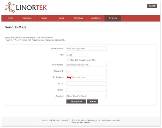
Zodra u op “Opslaan/Test” klikt, verzendt het apparaat automatisch de test-e-mail. Controleer de map Ongewenst/Overig om deze te vinden als deze zich niet in de map Inbox bevindt.
Stap 4. Stel de taak in voor automatische e-mailmeldingen.
You should be able to receive email notifications for various events from the Fargo/Koda boards at this point. If you need to receive condition logic notification, you can use our condition logic configuration to setup such report. To setup the logic condition report notification, go to Tasks page on your Fargo/Koda device, click the Edit icon of a Schedule. For details of how to create a logic-based event, please refer to the Set Schedule Page on the Fargo/Koda User Manual, which can be downloaded here:
https://www.linortek.com/download/fargo%20g2_koda%20downloads/fargo%20g2_koda%20documentation/Fargo-G2-and-Koda-User-Manual.pdf
In deze sample We zullen het Network Hour Meter-apparaat gebruiken als example voor hoe u elke dag om 11:52 uur e-mailrapporten kunt ontvangen.
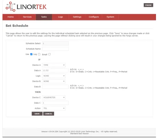
Zodra aan alle voorwaarden van de taak is voldaan, ontvangt u de volgende e-mail:
Hour Reading Report
![]() ondersteuning@linortek.com
ondersteuning@linortek.com
Mon 4/11/2022 11:52 AM
To: Liyu Nalven
HM 1, my machine, is at 000242.01 hrs.
Reply Forward
![]()
Documenten / Bronnen
 |
LINORTEK Fargo G2 TCP/IP Web Op relais gebaseerde controller [pdf] Gebruikershandleiding Fargo G2, Koda, Fargo G2 TCP-IP Web Based Relay Controller, Web Based Relay Controller, Based Relay Controller, Relay Controller |