![]() Fargo G2 and Koda User Manual
Fargo G2 and Koda User Manual
www.linortek.com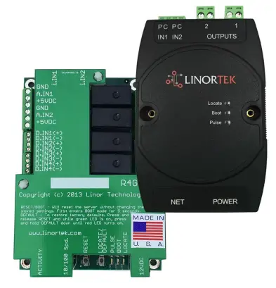 For Fargo G2, Koda
TCP/IP Web Controlador de relés baseado
Rev C 04/2022
Fargo G2 TCP/IP Web Controlador de relés baseado
Thank you for purchasing a Linortek Fargo G2 or Koda TCP/IP Controller. There are many devices that can be controlled by the FARGO/KODA Web Relay Controller. FARGO/KODA Web Controller can be used in such applications as (but not limited to): Lights, security, sprinkler systems, access control, industrial equipment, building automation, HVAC, and many more. Please refer to the Board Reference Layouts on page 29 for input and output specifications on your controller to verify they are suitable to your needs.
Este manual abrangue:
- FARGO R8 G2
- FARGO R4DI G2
- FARGO R4ADI G2
- KODA 100
- KODA200
These will be referred to as SERVER hereafter. When there are differences or additional features they will be noted in the text.
Para obter vídeos instrutivos, preguntas frecuentes e información de contacto do noso equipo de soporte técnico, visite: https://www.linortek.com/technical-support
GARANTÍA LIMITADA A UN ANO DE LINORTEK
Consumer law: For consumers who are covered by consumer protection laws or regulations in their country of residence (“Consumer Law”), the benefits provided in this Linortek One-Year Limited Warranty (“Linortek Limited Warranty”) are in addition to and not instead of the rights provided by Consumer Law and it does not exclude, limit or suspend your rights arising from Consumer Law. You should consult the proper authorities in your country of residence for further information about these rights
As obrigas de garantía de Linortek para este produto de hardware ("Produto") limítanse aos termos que se indican a continuación:
Linor Technology, Inc. (“Linortek”) warrants this product against defects in materials and workmanship for a period of ONE (1) YEAR from the date of retail purchase by the original end-user purchaser (“Warranty Period”) when used in accordance with the operating instructions. A copy of a retail receipt is required as proof of purchase. If a hardware defect arises and a valid claim is received within the Warranty Period, at its option and to the extent permitted by law, Linortek will either (1) repair the hardware defect at no charge, using new or refurbished replacement parts, (2) exchange the product with a product that is new or which has been manufactured from new or serviceable used parts and is at least functionally equivalent to the original product, or (3) refund the purchase price of the product. When a refund is given, the product for which the refund is provided must be returned to Linortek and becomes Linortek’s property.
A garantía anterior está suxeita a (i) a pronta reclamación por escrito do Comprador e (ii) a subministración oportuna a Linortek da oportunidade de inspeccionar e probar o Produto que se afirma como defectuoso. Tal inspección pode realizarse nas instalacións do Comprador e/ou Linortek pode solicitar a devolución do Produto por conta do Comprador. Non obstante, Linortek non será responsable dos custos de embalaxe, inspección ou traballo relacionados coa devolución do Produto. Non se aceptará ningún produto para o servizo de garantía que non estea acompañado dun número de autorización de devolución de mercadorías (RMA#) emitido por Linortek.
EXCLUSIÓNS E LIMITACIÓNS
Esta Garantía limitada exclúe os danos derivados de abuso, mal uso, neglixencia, incendio ou outras causas externas, accidentes, modificacións, reparacións ou outras causas que non sexan defectos nos materiais e na fabricación. O software distribuído por Linortek con ou sen a marca Linortek, incluíndo, entre outros, o software do sistema ("Software") non está cuberto por esta Garantía Limitada. O seu uso e dereitos asociados co Software están rexidos polo Acordo de licenza de usuario final de Linortek que pode atopar aquí: https://www.linortek.com/end-user-licenseagreement/. Linortek non se fai responsable dos danos derivados do incumprimento das instrucións relativas ao uso do produto. Para garantir o cumprimento das limitacións de funcionamento, o comprador debe consultar o manual de instrucións [proporcionado co produto]. As baterías non están incluídas na garantía.
NA MEDIDA MÁXIMA PERMITIDA, ESTA GARANTÍA LIMITADA E OS RECURSOS ESTABLECIDOS ANTERIORMENTE SON EXCLUSIVOS E EN LUGAR DE TODAS OUTRAS GARANTÍAS, RECURSOS E CONDICIÓNS, E LINORTEK RENUNCIA ESPECÍFICAMENTE A TODAS LAS GARANTÍAS LEGAIS OU IMPLÍCITAS, INCLUÍDAS GARANTÍAS LIMITADAS, GARANTÍAS LIMITADAS, GARANTÍAS NON INCLUÍDAS. ADECUACIÓN PARA UN FIN PARTICULAR, NON INFRACCIÓN. TANTO TANTO QUE DITAS GARANTÍAS NON SE PODEN RENUNCIAR, TODAS ESTAS GARANTÍAS DEBERÁN LIMITARSE NA DURACIÓN Á DURACIÓN DA GARANTÍA LIMITADA DE LINORTEK E O REMEDIO LIMITARÁSE Á REPARACIÓN, SUSTITUCIÓN OU REEMBOLSO QUE DETERMINA LINORTEK. Á SÚA ÚNICA DISCRECIÓN. ALGÚNS ESTADOS (PAÍSES E PROVINCIAS) NON PERMITEN LIMITACIÓNS SOBRE O TEMPO QUE PODE DURAR UNHA GARANTÍA OU CONDICIÓN IMPLÍCITA, POLO QUE AS LIMITACIONS DESCRITAS ANTERIORMENTE NON SE APLICAN A TI. ESTA GARANTÍA CONTÉNCHELE DEREITOS LEGALES ESPECÍFICOS, E TAMÉN PODE TER OUTROS DEREITOS QUE VARÍAN DE ESTADO A ESTADO (OU POR PAÍS OU PROVINCIA). ESTA GARANTÍA LIMITADA REXÍSE E INTERPRÉTESE BAIXO AS LEIS DOS ESTADOS UNIDOS.
Exencións de responsabilidade
- Lea as instrucións: lea todas as instrucións de seguridade e de funcionamento antes de utilizar o produto.
- Conserve as instrucións: conserve as instrucións de seguridade e de funcionamento para futuras consultas.
- Ten en conta as advertencias: siga todas as advertencias do produto e das instrucións de funcionamento.
- Siga as instrucións: siga todas as instrucións de funcionamento e uso.
- Limpeza: desconecte o produto da alimentación antes de limpar. Non utilice produtos de limpeza líquidos nin produtos de limpeza en aerosois. Usa anuncioamp pano só para limpar o recinto.
- Anexos: non utilice anexos a non ser que sexan recomendados específicamente por Linortek. Usar accesorios incompatibles ou inadecuados pode ser perigoso.
- Accesorios: non coloque este produto nun soporte, trípode, soporte ou soporte inestable. O produto pode caer, causando feridas graves a unha persoa e danos graves ao produto. Use só cun soporte, trípode, soporte ou soporte recomendado polo fabricante ou vendido co produto. Siga as instrucións do fabricante cando monte o produto e use só accesorios de montaxe recomendados polo fabricante. Teña coidado ao utilizar unha combinación de aparello e carro. As paradas rápidas, a forza excesiva e as superficies irregulares poden facer que a combinación do aparello e do carro se envorque.
- Ventilación: as aberturas no recinto, se as houbese, están previstas para a ventilación e para garantir un funcionamento fiable do produto e protexelo do sobrequecemento. Non bloquee nin cubra estas aberturas. Non coloque este produto nunha instalación integrada a menos que se proporcione unha ventilación adecuada ou se cumpran as instrucións de Linortek.
- Fontes de enerxía: utilice este produto só co tipo de fonte de enerxía indicado no manual de instrucións ou na etiqueta do produto.
Se non está seguro do tipo de fonte de enerxía que planea utilizar, consulte co seu distribuidor de electrodomésticos ou compañía eléctrica local, sempre que o uso de calquera tipo de fonte de enerxía diferente ao indicado no manual de instrucións ou na etiqueta de marcado anulará calquera garantía. Para produtos destinados a funcionar con batería ou outras fontes, consulte as instrucións de funcionamento [incluídas co produto]. - Conexión a terra ou polarización: este produto pode estar equipado cun enchufe polarizado de corrente alterna (un enchufe que ten unha lámina máis ancha que a outra). Este enchufe encaixará na toma de corrente só dun xeito. Esta é unha característica de seguridade. Se non pode inserir o enchufe completamente na toma de corrente, intente invertir o enchufe. Se o enchufe aínda non encaixa, é porque a súa toma é incompatible co enchufe. Póñase en contacto co seu electricista para substituír a súa toma de corrente por outra que sexa compatible. Non forzar o enchufe a encaixar nunha toma de corrente incompatible nin tentar evitar o propósito de seguridade do enchufe. Alternativamente, este produto pode estar equipado cun enchufe de 3 fíos de tipo conexión a terra, un enchufe que teña un terceiro pin (conexión a terra). Este enchufe só encaixará nunha toma de corrente con conexión a terra. Esta é unha característica de seguridade. Non forzar o enchufe a encaixar nunha toma de corrente incompatible nin tentar evitar o propósito de seguridade do enchufe. Se a súa toma de corrente é incompatible coa toma, póñase en contacto co seu electricista para substituír a súa toma por outra que sexa compatible.
- Protección do cable de alimentación: encamiña os cables de alimentación de xeito que non sexan susceptibles de ser pisados ou pinchados por elementos colocados enriba ou contra eles, prestando especial atención aos cables e enchufes, aos receptáculos e ao punto de saída dos cables do aparello. .
- Liñas eléctricas: non coloque un sistema exterior en ningún lugar nas proximidades de liñas eléctricas aéreas ou doutros circuítos eléctricos ou de luz eléctrica, ou onde poida caer sobre tales liñas ou circuítos eléctricos. Ao instalar un sistema ao aire libre, teña moito coidado para evitar tocar as liñas eléctricas ou circuítos, xa que o contacto con eles pode ser fatal.
- Sobrecarga: non sobrecargue as tomas de corrente nin os cables de extensión, xa que poden provocar incendios ou descargas eléctricas.
- Entrada de obxectos e líquidos: non introduza nunca obxectos de ningún tipo dentro deste produto a través das aberturas, xa que poden tocar un volume perigoso.tage puntos ou partes curtas que poden provocar incendios ou descargas eléctricas. Nunca derrames líquido de ningún tipo sobre o produto.
- Reparación: non intente reparar este produto por si mesmo xa que abrir ou quitar as tapas pode exporse a volúmenes perigosos.tage ou outros perigos. Envíe todos os servizos de mantemento do produto a Linortek.
- Danos que requiren servizo: Desenchufe o produto da toma de corrente e solicite o servizo de atención ao cliente de Linortek nas seguintes condicións:
a. Cando o cable ou o enchufe de alimentación estean danados.
b. Se se derramou líquido ou se caeron obxectos sobre o produto.
c. Se o produto estivo exposto á chuvia ou á auga.
d. Se o produto non funciona normalmente seguindo as instrucións de funcionamento [incluídas co produto]. Axuste só os controis que estean contemplados nas instrucións de funcionamento, xa que un axuste inadecuado doutros controis pode producir danos e moitas veces requirirá un traballo extenso por parte dun técnico cualificado para restaurar o produto ao seu funcionamento normal.
e. Se o produto caeu ou o armario estivo danado.
f. Se o produto presenta un cambio distinto no rendemento. - Pezas de recambio - Se é necesario substituír pezas, teña un baixo volumetage O electricista substitúeos só usando pezas especificadas polo fabricante. As substitucións non autorizadas poden provocar incendios, descargas eléctricas ou outros perigos. As pezas de recambio pódense atopar en https://www.linortek.com/store/
- Comprobación de seguridade: ao completar calquera servizo ou reparación deste produto, solicite ao técnico de servizo que realice comprobacións de seguridade para determinar que o produto está en condicións de funcionamento axeitados.
- Conexión a terra coaxial: se se conecta un sistema de cable externo ao produto, asegúrese de que o sistema de cable estea conectado a terra. Só modelos dos EUA: a sección 810 do Código Eléctrico Nacional, ANSI/NFPA No.70-1981, proporciona información sobre a correcta conexión a terra do soporte e estrutura de apoio, a conexión a terra do coaxial a un produto de descarga, o tamaño dos condutores de posta a terra, a localización. do produto de descarga, conexión aos electrodos de posta a terra e requisitos para o electrodo de posta a terra.
- Raios: para obter unha maior protección deste produto durante unha tormenta eléctrica ou antes de deixalo desatendido e sen usar durante longos períodos de tempo, desconécteo da toma de corrente e desconecte o sistema de cables. Isto evitará danos ao produto debido a raios e sobretensións da liña eléctrica.
- Uso ao aire libre: este produto non é impermeable e non se debe permitir que se molle. Non expoña á choiva nin a outros tipos de líquidos.
Non deixes fóra da porta durante a noite xa que pode producirse condensación. - Ao cambiar as pilas, os fusibles ou a manipular un produto a nivel de placa, teña coidado coas descargas electrostáticas que poden danar os dispositivos electrónicos. É mellor empregar un banco de servizo electrónico conectado a terra. Se isto non está dispoñible, pode descargarse tocando un electrodoméstico ou un tubo metálico. Mentres cambie as pilas ou os fusibles, non toque i) ningún cable que non sexa os cables da batería e ii) a placa de circuíto impreso.
LIMITACIÓN DE RESPONSABILIDADE
IN NO EVENT WILL LINOR TECHNOLOGY BE LIABLE, WHETHER IN CONTRACT, TORT, OR OTHERWISE, FOR ANY INCIDENTAL, SPECIAL, INDIRECT, CONSEQUENTIAL OR PUNITIVE DAMAGES, INCLUDING, BUT NOT LIMITED TO, DAMAGES FOR ANY LOSS OF USE, LOSS OF TIME, INCONVENIENCE, COMMERCIAL LOSS, OR LOST PROFITS, SAVINGS, OR REVENUES TO THE FULL EXTENT SUCH MAY BE DISCLAIMED BY LAW. DISCLAIMER FOR CRITICAL APPLICATIONS
Este produto non está destinado nin autorizado para produtos de soporte vital nin para outros usos para os cales un fallo poida causar danos persoais ou a morte. Se vostede ou os seus clientes usan ou permiten o uso deste produto para tales usos non intencionados ou non autorizados, acepta indemnizar totalmente a Linor Technology e os seus afiliados, e aos oficiais, empregados e distribuidores de cada un, de toda responsabilidade relacionada con tal uso, incluíndo honorarios e costas dos avogados.
AVISO ADICIONAL PARA A LIMITACIÓN DE USO
A menos que se indique especificamente, os nosos produtos NON están deseñados para cambiar a liña de voltage (110 V ou superior). Para controlar dispositivos que funcionan na liña voltagun electricista cualificado DEBE instalar un dispositivo intermediario como un relé. Ao escoller os dispositivos para controlar, o mellor é seleccionar baixo voltage controis como un solenoide de 24 VCA para o control do fluxo de auga. Só os electricistas cualificados poden cablear unha liña voltage dispositivo. Ademais, débense seguir os códigos locais, incluíndo, entre outros, o calibre de cable e a carcasa adecuada. Linortek non asume ningunha responsabilidade por danos ao usuario ou a terceiros polo uso indebido dos nosos Produtos. Esta responsabilidade é do usuario. Linortek non asume ningunha responsabilidade polos danos no dispositivo debido a un uso inadecuado dos nosos produtos.
RELÉ VOLTAGE ESPECIFICACIÓNS
Teña coidado ao conectar dispositivos a circuítos eléctricos ou outros equipos. Isto web O controlador NON está deseñado para conectarse a ningún voltage greater than 48V. Utilizing this arrangement, should allow you to virtually control anything. It is important that you use licensed electricians and comply with electrical codes that are applicable to your location. These codes exist for your safety, as well as the safety of others. Linortek assumes no responsibility for any harm or damage resulting from a failure adhere to local laws, ordinances or regulations or failure to follow specified instructions for installation and product usage.
Acordo de licenza de usuario final para o software e a documentación de Linortek
Este Acordo de Licenza de Usuario Final ("CLUF") é un acordo legal entre TI (unha persoa individual ou única entidade) e Linor Technology, Inc. ("Linortek" ou "nós" ou "nós") que regula o seu uso do software. e documentación ("Software") integrado ou asociado ás series de produtos Fargo, Koda, Netbell, IoTMeter e iTrixx ("Produtos Linortek").
Este EULA non rexe o uso do Linortek websitio ou os Produtos Linortek (excluído o Software). O teu uso do Linortek websitio está gobernado por Linortek webCondicións de servizo do sitio e a política de privacidade de Linortek que se pode consultar en:
http://www.linortek.com/terms-and-conditions [A súa compra de produtos de Linortek (excluído o software) está rexida pola garantía limitada de Linortek, que se pode atopar en https://www.linortek.com/linortek-one-year-limited-warranty/
This EULA governs your access and use of the Software. This EULA gives you specific legal rights, and you may also have other legal rights in addition, which vary from jurisdiction to jurisdiction. The disclaimers, exclusions, and limitations of liability under
this EULA will not apply to the extent prohibited or limited by applicable law. Some jurisdictions do not allow the exclusion of implied warranties or the exclusion or limitation of incidental or consequential damages or other rights, so those provisions of this EULA may not apply to you.
Ao instalar, acceder, copiar e/ou utilizar o Software ou a documentación, acepta estar obrigado polos termos e condicións deste EULA en nome propio ou da entidade que representa en relación con tal instalación, acceso, copia e/ou usar. Vostede declara e garante que (i) ten o dereito, a autoridade e a capacidade de aceptar e aceptar os termos deste EULA en nome propio ou da entidade que representa (ii) ten a idade legal suficiente na súa xurisdición de residencia. , (iii) non se atopa nun país que estea suxeito a un embargo do goberno dos Estados Unidos ou que o goberno dos Estados Unidos designou como un país "de apoio ao terrorismo"; e (ii) non figura na lista de partes prohibidas ou restrinxidas do goberno dos Estados Unidos.
Se non desexa estar obrigado polos termos deste CLUF, non pode instalar, acceder, copiar ou utilizar o Software de ningún xeito (sexa ou non preinstalado nun dispositivo que adquiriu).
- Uso permitido de software/Licenza de software.
Suxeito aos termos deste EULA, Linortek outórgache un dereito e unha licenza limitados, revogables, non exclusivos, non sublicenciables e non transferibles para (a) descargar, instalar e executar unha copia do Software, en forma de código obxecto executable. únicamente no Produto Linortek que posúe ou controle e para (b) utilizar o Software únicamente en relación co Produto Linortek de acordo co seu uso previsto como se describe no Linortek. websitio (cada un dos 1(a) e 1(b) un "Uso permitido" e colectivamente "Usos permitidos"). - Restricións ao uso do software.
Acepta non e non permitir que outros utilicen o Software para ningún propósito que non sexa os Usos Permitidos descritos na Sección 1 anterior. Isto significa, entre outras cousas, que non pode:
(a) editar, alterar, modificar, adaptar, traducir, facer traballos derivados, desmontar, realizar enxeñaría inversa ou compilar inversamente calquera parte do Software (excepto na medida en que as leis aplicables prohiban especialmente tal restrición para fins de interoperabilidade, en cuxo caso aceptas poñerse en contacto primeiro con Linortek e proporcionarlle a Linortek a oportunidade de crear os cambios que sexan necesarios para fins de interoperabilidade);
(b) licenciar, asignar, distribuír, transmitir, vender, alugar, aloxar, terceirizar, divulgar ou utilizar o Software para calquera propósito comercial ou poñer o Software a disposición de terceiros;
(c) permitir que calquera terceiro utilice o Software en nome ou en beneficio de calquera terceiro;
(d) utilizar calquera parte do Software en calquera dispositivo ou ordenador que non sexa o Produto Linortek que posúe ou controle;
(e) utilizar o Software de calquera forma que infrinxa calquera lexislación local, nacional ou internacional aplicable; ou
(f) remove or alter any labels, symbols, legends or proprietary notices, including but not limited to any copyright, trademark, logo in the Software. You may not disclose the results of any performance or functional evaluation of anyof the Software to any third party without the prior written consent of Linortek for each such release. - Actualizacións.
De cando en vez, Linortek pode desenvolver actualizacións, actualizacións, parches, correccións de erros e outras modificacións ("Actualizacións") para mellorar o rendemento do Software. Salvo que se indique o contrario no Linortek websitio, estas Actualizacións serán proporcionadas para vostede de forma gratuíta. Estas actualizacións poden instalarse automaticamente sen previo aviso. Ao usar o Software, tamén aceptas as actualizacións automáticas. Se non está de acordo con isto, non poderá instalar, acceder, copiar ou utilizar o Software de ningún xeito. - Propiedade.
The Software is licensed to you and not sold. Linortek reserves all rights to the Software and any Updates not expressly granted herein. The Software and Linortek Products are protected by copyright, trademark and other intellectual property laws andtreaties. Linortek and its licensors own the title, copyright, trademarks and other intellectual property rights in the Software.
You are not granted any rights to Linortek’s trademarks or service marks. There are no implied licenses in this EULA. - Terminación.
This EULA is effective from the date you first use the Software and will continue for as long as you own the Linortek Product associated with it or until you or Linortek terminate this agreement under this section. You may terminate this EULA at any time upon written notice to Linortek at the address provided below. Linortek may terminate this EULA at any time if you fail to comply with any of the terms in this agreement. The license granted in this EULA terminates immediately when the agreement terminates. Upon termination, you must stop using the Linortek Product and the Software and you must delete all copies of the
Software. The terms of Sections 2 will still remain in effect after the agreement terminates. - Exención de responsabilidade da garantía.
EXTENT PERMITTED BY APPLICABLE LAW, LINORTEK PROVIDES THE SOFTWARE “AS-IS” AND DISCLAIMS ALL WARRANTIES AND CONDITIONS, WHETHER EXPRESS, IMPLIED, OR STATUTORY, INCLUDING THE WARRANTIES OF MERCHANTABILITY, FITNESS FOR A PARTICULAR PURPOSE, TITLE, QUIET ENJOYMENT, ACCURACY, AND NON-INFRINGEMENT OF THIRD-PARTY RIGHTS. LINORTEK DOES NOT GUARANTEE ANY SPECIFIC RESULTS FROM THE USE OF THE SOFTWARE. LINORTEK MAKES NO WARRANTY THAT THE SOFTWARE WILL BE UNINTERRUPTED, FREE OF VIRUSES OR OTHER HARMFUL CODE, TIMELY, SECURE, OR ERROR-FREE. YOU USE THE SOFTWARE AND THE LINORTEK PRODUCT AT YOUR OWN DISCRETION AND RISK. YOU WILL BE SOLELY RESPONSIBLE FOR (AND LINORTEK DISCLAIMS) ANY AND ALL LOSS, LIABILITY, OR DAMAGES RESULTING FROM YOUR USE OF THE SOFTWARE
AND LINORTEK PRODUCT. - Limitación de responsabilidade.
Nada do presente EULA e, en particular, desta cláusula de "Limitación de responsabilidade" tentará excluír a responsabilidade que non se poida excluír segundo a lexislación aplicable.
NA MEDIDA MÁXIMA PERMITIDA POLA LEI APLICABLE, ADEMAIS DAS EXENCIÓNS DE GARANTÍA ANTERIORES, EN NINGÚN CASO (A) LINORTEK SERÁ RESPONSABLE DE NINGÚN DANOS CONSECUENTES, EXEMPLARS, ESPECIAIS OU INCIDENTAIS, INCLUÍDOS CALQUERA DANOS, OU PERDA DE DATOS POR PERDA DE DATOS. DOS PRODUTOS OU DO SOFTWARE OU RELACIONADO CON COS, AÍNDA QUE LINORTEK COÑECÍA OU DEBERÍA COÑECER A POSIBILIDADE DE TALES DANOS, E (B) A RESPONSABILIDADE TOTAL ACUMULADA DE LINORTEK DERIVADA DOS PRODUTOS, OUTROS PRODUTOS E SOFTWARE, OU RELACIONADAS CONOS SERÁ LIMITADO A UNHA IMPORTE QUE NUNCA SUPERE O IMPORTE REALMENTE PAGADO POR TI AO DISTRIBUIDOR AUTORIZADO OU O REPRESENTANTE DE VENDAS DE LINORTEK E DOS PRODUTOS OU SERVIZOS EN PROBLEMA NOS 6 MESES ANTERIORES (SE O HAI O HOXE). ESTA LIMITACIÓN É ACUMULATIVA E NON SE AUMENTARÁ POLA EXISTENCIA DE MÁIS DUN INCIDENTE OU RECLAMACIÓN. LINORTEK RENUNCIA A TODA RESPONSABILIDADE DE CALQUERA TIPO DE LICENCIADORES E PROVEEDORES DE LINORTEK. - Cumprimento das leis de exportación.
Vostede recoñece que o Software e a tecnoloxía relacionada están suxeitos ás leis de control de exportacións de EE. Acepta cumprir estritamente todas as leis e regulamentos internacionais e nacionais aplicables que se aplican ao Software, incluídas as Normas de Administración de Exportacións dos Estados Unidos, así como as restricións de usuarios finais, de uso final e de destino emitidas polos gobernos dos Estados Unidos e outros. Vostede recoñece que ten a responsabilidade de obter autorización para exportar, reexportar ou importar o Software e tecnoloxía relacionada, segundo sexa necesario.
Indemnizará e exonerará a Linortek de todas as reclamacións, perdas, responsabilidade, danos, multas, sancións, custos e gastos (incluídos os honorarios dos avogados) derivados ou relacionados con calquera incumprimento das súas obrigas en virtude desta sección. - Asignación.
Non pode ceder ningún dos seus dereitos ou obrigas conforme a este EULA, e calquera intento de asignación será nulo e sen efecto. - Avisos.
Linortek pode fornecerlle calquera notificación relacionada con este EULA utilizando o correo electrónico e o enderezo que proporcionou cando se rexistrou en Linortek. - Renuncia
Para que sexan efectivas, todas e todas as renuncias de Linortek abaixo deben ser por escrito e asinadas por un representante autorizado de Linortek. Calquera outro incumprimento de Linortek para facer cumprir calquera dos termos a continuación non se considerará unha renuncia. - Separabilidade.
Calquera disposición deste EULA que se considere inaplicable editarase e interpretarase para acadar os obxectivos desta disposición na maior medida posible segundo a lexislación aplicable e todas as disposicións restantes permanecerán en pleno vigor e efecto. - Dereito vixente; Lugar.
You agree that this EULA, and any claim, dispute, action, cause of action, issue, or request for relief arising out of or relating to this EULA, will be governed by the laws of the state of North Carolina, U.S.A., without regard to conflicts of laws principles, provided that if you reside in a country that will not apply U.S. law to disputes related to these terms, then the laws of your country will apply. You also agree that the United Nations Convention on Contracts for the International Sale of Goods shall not
apply. You agree that regardless of any statute or law to the contrary, any cause of action against us arising out of or related to the Linortek websitio, o Software ou os Produtos de Linortek deben comezar dentro dun (1) ano despois de que se produza a causa da acción ou dita causa de acción quedará prohibida permanentemente. Calquera acción ou procedemento relacionado con este EULA debe presentarse nun xulgado federal ou estatal situado en Raleigh, Carolina do Norte e cada parte sometese irrevogablemente á xurisdición e ao lugar de celebración de tales tribunales en calquera reclamación ou disputa, agás que Linortek poida solicitar medidas cautelares. compensación en calquera tribunal que teña xurisdición para protexer a súa propiedade intelectual. - Aviso da Proposición 65 de California.
 AVISO: Este produto pode expoñelo a produtos químicos, incluído o chumbo, que o Estado de California sabe que causa cancro. Para obter máis información, visite www.P65Warnings.ca.gov.
Comezando
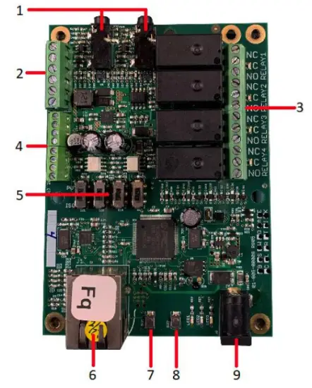
The Fargo SERVER is what is called a “bare board” product and is supplied without a housing. It operates on low voltage; however you need to use simple handling precautions to prevent damage to the circuits. All electronics are susceptible to electrostatic discharge. This high voltage “shock” can permanently damage your device. Before handling the product, you should touch a surface such as a grounded workbench or table. It is also best to handle the device from its edges. If you notice that your chair or clothes often cause static discharges, you must exercise extra caution. The unit is supplied with four rubber feet which keeps the bottom of the board from coming into contact with the surface you put it on. Be careful not to let metal objects, such as screw drivers or hardware, come in contact with the bottom of this product. The board can be mounted on a panel using stand offs and #4 hardware. The mounting holes are connected to the GROUND signal. The SERVER unit is a self-contained web server configured with various input and output circuits. Although the relays are rated for higher voltages, este produto non está deseñado para o seu uso en liña voltages. You should never use voltages through the SERVER product exceeding 48 volts. IT IS NOT SAFE.
The KODA SERVER is a housed unit with a DIN rail mountable enclosure that can be snapped onto a DIN rail or attached to any flat surface such as a wall or under a counter. KODA 100 has two relays (48VAC@1A), KODA 200 has four relays which can drive 10V 50mA to external devices. The unit is supplied with a DIN Rail mountable enclosure with removable terminal connectors for easy installation. The KODA SERVER can be mounted on a panel or on the wall using the DIN rail mount clip. The removable wire terminal connectors simplify field installation and allow for easy troubleshooting and maintenance: the unit can be removed from the system without disturbing the system wiring.
Cableado do servidor
Nota: For a diagram showing the location of all connectors on your SERVER referenced in this section, please see the section – Board Layout Reference.
Atención: Estas unidades están illadas ao chan. Conéctese sempre para que o bucle de alimentación só estea conectado á unidade SERVIDOR.
NON use conexións a terra externas. Facelo pode danar o SERVIDOR ou o dispositivo de orixe POE.
- Place the unit on a table or bench being careful not to let any metal objects come into contact with the bottom of the circuit board (Fargo Only).
- Connect the 12VDC power supply to a suitable AC outlet and plug the barrel connector into the SERVER at the location labelled “12VDC/POWER”. Alternatively, you may also use POE. At this point the GREEN/Boot LED should come on and start flashing indicating the SERVER is operating and is in the “Bootload Mode”. This mode allows the user to update the server software that is used on the unit. After about 5 seconds, the GREEN LED will go off and the RED LED will start blinking once per second indicating the SERVER is operating in “Server Mode” and is accessible on a network utilizing TCP/IP protocols.
PRECAUCIÓN: CANDO UTILICE O INTERRUPTOR DE REDE POE, NON USE A FONTE DE ALIMENTACIÓN DE 12 VCC PARA ALIMENTAR AO SERVIDOR AO MESMO TEMPO, DANARÁ A PLACA. - Plug an Ethernet cable into the RJ45/NET connector. The “Connection” LED will come on if a 100MHz network is available, otherwise it will remain off and the “Activity” LED should start blinking indicating network activity. Fargo G2 Relay Connections
There are 8 relays on the FARGO R8 and 4 on the FARGO R4. These are dry contact relays. These units are designed for only low voltage control e non debe ter un voltage applied to the relay greater than 48 volts. This is for your safety as well as to stay within the parameters of the parts and circuit board design. The relays have 3 terminals labelled NO, C and NC which stand for Normally Open, Common and Normally Closed. When activated, the relay moves the connection from CNC to CNO. If you want to make a connection when the relay is activated, connect your wires between C and NO. When the relay is activated C and NO will be connected together. If you want to break a circuit when the relay is activated, make your connections to C and NC. When the relay is activated the circuit will be broken (or open)
Koda Relay Connection
There are 2 relays on the KODA 100. The KODA 100 has 2 removable 2 position connectors (1 for each relay) and are simply numbered “1” and “2”. These relays are normally open.
There are 4 relays on the KODA 200. The KODA 200 has 1 removable 8 position connector. Each relay has a “+” connection and a numbered connection. The relays may be set to supply about 10VDC by selecting “+V” on the setting switch (see Board Layout Reference page 29) or set to dry contact DC on the switch. If “+V” is selected then the voltage will be present on the “+” terminal and the numbered terminal is the return. Otherwise, a normally open dry contact exists across the “+” and numbered connection. KODA 100/200 is designed for only low voltage control e non debe ter un voltage aplicado ao relé superior a 48 voltios. Isto é para a súa seguridade e para manterse dentro dos parámetros das pezas e do deseño da placa de circuíto.

![]() EN NINGÚN CASO LINOR TECHNOLOGY SERÁ RESPONSABLE, SEN CONTRATO, EXTRAORDINARIO OU OUTRO MODO, DE NINGÚN DANO ACCIDENTAL, ESPECIAL, INDIRECTO, CONSECUENTE OU PUNITIVO, INCLUÍDOS, PERO NON LIMITADO A, DANOS POR CALQUERA PERDA DE USO, PERDA DE TEMPO, , A PERDA COMERCIAL OU A PERDA DE BENEFICIOS, AFORROS OU INGRESOS EN TODA A MEDIDA PODEN NEGARSE POR LEI.
EN NINGÚN CASO LINOR TECHNOLOGY SERÁ RESPONSABLE, SEN CONTRATO, EXTRAORDINARIO OU OUTRO MODO, DE NINGÚN DANO ACCIDENTAL, ESPECIAL, INDIRECTO, CONSECUENTE OU PUNITIVO, INCLUÍDOS, PERO NON LIMITADO A, DANOS POR CALQUERA PERDA DE USO, PERDA DE TEMPO, , A PERDA COMERCIAL OU A PERDA DE BENEFICIOS, AFORROS OU INGRESOS EN TODA A MEDIDA PODEN NEGARSE POR LEI.
AVISO ADICIONAL PARA A LIMITACIÓN DE USO
A menos que se indique especificamente, este produto NON está deseñado para cambiar a liña de voltagdispositivos e. Esta limitación inclúe todos os produtos FARGO E KODA. Para controlar dispositivos que funcionan na liña voltagé o usuario DEBE instalar un dispositivo intermediario como un relé.
Ao cablear unha liña voltagNo dispositivo que utiliza un dispositivo intermediario, DEBE ser un electricista cualificado ou utilizar os servizos dun electricista cualificado. Ademais, débense seguir os códigos locais, incluíndo, entre outros, o calibre do cable e a carcasa adecuada.
Linortek cannot assume any responsibility for harm to the user or third parties for improperly using our Fargo/Koda products. This liability remains with the user. Linortek cannot assume any responsibility for damage to the device for improperly using our SERVER product.
For relay specifications, please see Board Reference Layout page 29
Digital Input Connections (Fargo R4 and Koda)
The digital inputs allow the SERVER to detect an external on/off state of a sensor. With this information the SERVER can display whether an input is on or off, count events in a resettable or non-resettable counter, and calculate the frequency (such as for use as a tachometer) or the period of the input. There are two modes of operation for the digital inputs – PULL UP and ISOLATED.
a) PULL UP mode connects a 1K resistor to an internal voltage que lle permite usar un interruptor sinxelo (como un interruptor magnético de porta) nos terminais 1 e 2. Isto cando o interruptor está activado envíase un sinal á entrada.
b) ISOLATED mode allows you to directly drive the SERVER’s optoisolator with an external voltage aínda que unha resistencia interna de 1K. Este voltage pode estar no intervalo de 5V a 24V subministrando un mínimo de 2mA ou un máximo de 30mA ao díodo optoisolador. Non hai outra conexión interna con este voltage so it is an isolated input. Please note, when connecting a 12VDC-¬24VDC circuit to the input, an external resistor (can be provided at request, 2.2k ohm 0.5watt) must be used.
These modes are selected by the switch on the SERVER (see Board Layout Reference page 29) marked ISO and PU for isolated and pull up respectively. These are set at the factory to ISO by default.
Wiring a push button: For distances up to 500 feet, a 20 AWG shielded wire is suitable for wiring a push button. If the distance between the push button and the controller extends up to 5,000 feet, use a 16 AWG shielded cable instead. Keep in mind that longer cable runs are more susceptible to signal interference.
Atención: If you intend to use isolated mode, verify that the input switch is set to ISO before applying an external voltage. Facer o contrario pode danar o SERVIDOR ou o dispositivo de orixe POE.
Analog Input Connections (Fargo R4ADI)
The analog inputs allow the SERVER to read the value of external equipment. There are 2 analog inputs.
For AC current monitoring, use one of the two 3.5mm stereo inputs to interface with a current sensor.
Os 2 bloques de terminais de entrada analóxica están conectados a sensores de corrente de 0-5 V non illados que poden conectarse a unha variedade de dispositivos, como sensores de temperatura ou presión. O SERVIDOR proporciona unha conexión a terra e alimentación para que as medicións se poidan realizar sen volúmenes externostage references. You should use a sensor that is isolated so that that it makes no connection to a remote ground. See drawing under Board Reference Layout page 29.
Accessing your SERVER
Unha vez que o SERVIDOR estea acendido e conectado á rede, obterá automaticamente un enderezo IP a través de DHCP sempre que o seu enrutador estea configurado para iso. Para conectarse, introduza o enderezo IP no seu web browser. This will take you to your SERVER’s landing page. To log in, click the Log In button on the top right of the page. Your browser will prompt you to enter your username and password. By default, these credentials are both set to admin. To find your SERVER’s IP address, see below.
Atopa o teu enderezo IP con Linortek Discoverer
O programa Discoverer localizará automaticamente o teu SERVIDOR. Discoverer é un programa Java e require a instalación de Java Runtime para usar esta función. Java pódese atopar aquí: http://java.com/en/download/index.jsp.
Para descargar o programa Discover, vai a: https://www.linortek.com/downloads/supportprogramming/
Recoméndase o uso dos navegadores Chrome e Firefox. Teña en conta: se prefire usar Internet Explorer, Internet Explorer garda Linortek Discoverer como Zip file por defecto. Para usar o Discoverer, terás que seleccionar Gardar como e renomear file como Linortek Discoverer.jar ao descargar.
Cando descargues o programa Discover, ás veces verás unha mensaxe de aviso emerxente dependendo da configuración de seguranza do teu navegador, preguntando se queres conservalo ou descartalo. file, please click the Keep button as this is a Java program, and it won’t harm your computer.
Unha vez que Discoverer localice o teu dispositivo, mostrará:
- Enderezo IP
- Nome do anfitrión
- Enderezo MAC
- Outra información:
a. LED azul (se está acendido)
b. Nome do produto
c. Revisión do software do servidor
d. Número de porto (se está portado)

Fai clic no dispositivo que queres usar que aparece no programa Discoverer para iniciar o SERVIDOR web pages in your browser. Click the Login button on the homepage. The default username/password is: admin/admin. You may change these as you desire or disable this feature in the settings menu.
Connecting your SERVER Directly to Your PC
You can also plug your SERVER directly to your PC if there is no network connection available. If you plug your SERVER into your PC’s Ethernet port it will use the default IP address: 169.254.1.1 unless you have previously configured your SERVER to use a static IP. Enter 169.254.1.1 into your web browser to connect. No internet connection is required. Once configured, you can then install your SERVER where you desired.
Configuración do servidor
Iniciando sesión
Once you have entered the IP address and port number, if set, the Login page will open. This page shows the name of this server which you may change in Configure/Network Config.
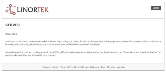
This page is static with no background activity and is a useful place to park if you are not using the SERVER and do not want to close the connection.
By pressing LOGIN, you will be asked for your username and password. These credentials will be retained by the browser until the browser is closed. You can disable the password requirement in Settings page. See section page 21.
Páxina de inicio
Unha vez que se introduzan as súas credenciais de inicio de sesión, será redirixido á páxina principal da aplicación. A páxina Inicio ou Índice mostra parte da información do sistema e ofrece a posibilidade de localizar o dispositivo físico se está nunha zona con outras. Vexa a lista a continuación para a descrición.

- TIME – Displayed along with the day of the week. This time may be set to be in a 12 hour format with AM/PM indicator or 24 hour format.
- DATA: aquí móstrase a data actual.
- VOLTIOS - Voltagmóstrase e no taboleiro. Isto pode ser útil se o SERVIDOR está alimentado xunto con outros equipos, voltage variance can be noted. Fargo and Koda servers have an input voltage range of 1248vDC.
- TEMPERATURE – Temperature on the board is displayed. This display may be either °C or °F. This temperature will be affected by the heat generated by SERVER itself so it will always be slightly higher than ambient temperature.
- LEDs: aparecen 3 LEDs. O LED VERMELLO é o pulso do sistema. Este debería parpadear aproximadamente unha vez por segundo mentres o servidor estea en funcionamento. O LED VERDE úsase para as opcións do cargador de arranque e xeralmente non é visible no websitio. O LED AZUL pódese facer clic e pode acendelo e apagalo desde isto web páxina. Isto é útil para localizar fisicamente o dispositivo se está en uso con outras unidades similares, xa que se iluminará na unidade á que este web navegador está conectado. O programa Discoverer tamén notará se o LED AZUL está acendido. A miúdo denomínase función "Localizar".
Servizos
A pestana Servizos é dinámica e cambiará dependendo da configuración do teu servidor. Aquí é onde podes controlar as entradas, saídas, sensores e outros controis especiais.
In/Out or Relays Page
Depending on which SERVER you are using, the first page on the SERVICES tab will be either In/Out or Relays.
In/Out has the relay controls and the input controls on one page, while Relays only has the relay controls.
Control de relé
An In/Out page is displayed below. Some relay control pages have 2, 4 or 8 relays displayed. Each relay has a number, in this case 1 to 4.

The State LED shows whether the relay is on or off indicated by GREEN and RED respectively. This icon is clickable to manually control the corresponding relay. Each relay can have a Name as well as identifiers for the Normally Open, Common and Normally Closed connections.
Hai catro LED de estado que mostran:
- Email – If an email is to be sent when this relay is switched on/off
- Pulso: se este relé está configurado cun ancho de pulso e un multiplicador de ancho de pulso (duración), consulte a seguinte sección para obter máis información
- Sched. – If there is a schedule created in the Tasks page (see page 15) set to automatically trigger this relay.
- Temporizado: se o pulso está configurado e este relé está activado, o LED temporizado irase en vermello indicando que o relé está a funcionar nun temporizador.
Click the Edit Icon to edit the controls for the corresponding relay. This will take you to the Set Relay page (see page 11).
Entradas
The In/Out or Inputs page (depending on your SERVER) will display information from each input. The SERVERs have a combination of inputs. The Fargo R4DI has four digital inputs, The R4ADI has, four digital inputs, four analog inputs. The KODA SERVER has two digital inputs.
At the top of each input is a label (ex: DIN 1, AIN 2) specifying whether it is a digital input (DIN) or analog input (AIN) as well as the input number. This label will turn green when the input is enabled. Inside the box will be any display configured from the Set Input page (see page 12 for digital input, page 14 for analog input). A red dot in the lower-left corner indicating the state of a linked relay (if any), will turn green when the linked relay is activated.
Finally, an Edit icon in the lower-right corner of the box to edit the corresponding input. This will take you to the Set Digital Input or Set Analog Input page (page 12 or page 14).
Set Relay Page
A páxina SET RELAY permítelle establecer varias propiedades relativas ao Relay.
- Relay Select – The Relay that you are editing (identified by the line on which you clicked the Edit icon on the RELAY page).
- Name – Enter a 15-character Relay Name. This and the following 3 fields may be used for any identifying information desired.
- NO Name – Enter a 7-character name for the Normally Open (NO) connection.
- Com Name – Enter a 7-character name for the Common (COM) connection.
- NC Name – Enter a 7-character name for the Normally Closed (NC) connection.
- Pulse Width – When you control the relay it turns on or off. You may control it for a timed turned on period by entering a Pulse Width when 0 means there is no timed event and a number represents duration of the pulse. The maximum number you can enter here is 4 digits, ie. 1234.
- Multiplicador de ancho de pulso: para definir aínda máis a lonxitude do pulso, seleccione un Multiplicador de ancho de pulso para definir aínda máis o ancho do pulso. Podes seleccionar:
• Non hai ningunha
• mS (Millisecond, 1/1000 second)
• Sec (Seconds)
• Min (Minutes) - Tipo de relé: o SERVIDOR pode acceder aos relés fisicamente no SERVIDOR ou mediante outros medios. Podes seleccionar:
• Normal – relay physically on the SERVER
• Latched – not currently supported
• Remote – a relay on another SERVER accessed over the network
• Zigbee – a relay at a remote device accessed over an RF system
• Normal and Remote – both relays activated
• Normal and Zigbee – both relays activated - ID de localización: este é un número que identifica unha localización remota
- Relé na localización: un número que representa o relé ou dispositivo na localización
- Enviar correo electrónico: o SERVIDOR pódese programar para enviar un correo electrónico se o relé está activado ou desactivado.

Establecer páxina de entrada dixital
As entradas dixitais pódense configurar para proporcionar varias lecturas sobre o uso dunha variedade de tipos de visualización. Ademais de mostrar os datos de entrada, pode nomear a pantalla e asociarlle un relé. Este relé cambiará de verde a VERMELLO a medida que vai de aceso a apagado, así como se pode facer clic para controlalo. Ao facer clic na icona de edición do lapis, pode editar a configuración desta entrada:
- Digital Input Selected – The Digital Input that you are editing (identified by the line on which you clicked the Edit icon).
- Nome: pode definir un nome de 15 caracteres para esta entrada. Este nome aparece na barra da parte superior da pantalla.
- Etiqueta: establece unha etiqueta de 7 caracteres que se mostra na pantalla activa real.
- Corrector: usando este campo pode sumar, restar, multiplicar ou dividir un valor antes de que o valor se mostre na páxina de visualización. Este é un corrector de 2 valores e cada un está separado por un único espazo. (é dicir, "+2, -2, *3, /3")
- USE – Establece esta entrada como activa. Pon o indicador do número de entrada en verde. Hai que ter en conta que cando está en uso a entrada consome tempo de CPU e outros recursos dependendo do seu tipo. Aínda que todas as entradas poden estar activas ao mesmo tempo, recoméndase activar só as que desexes usar.
- Tipo: os datos de entrada pódense usar para calcular un intervalo de resultados. Podes seleccionar:
• State – This is useful for knowing if an input is on or off, like a door switch being on or off.
• CounterNR – This is a non-resettable counter.
• CounterR – This is a resettable counter.
• Frequency – Counts the frequency of an input in KHz (kilo hertz or1/1000 seconds). This could be useful in displaying a tachometer where 60Hz = 1 R.P.M.
• Period – in 1/1000 seconds an input in kHz (milliseconds or1/1000 seconds). This would be useful for measuring timed events. - Pantalla: esta selección permítelle cambiar o tipo de visualización utilizado. Podes seleccionar:
• Dot – A single dot with the value in the middle. This can be used for State. You can make a dumb indicator by changing the color of the Dot based on the value. The label is under the Dot.
• Values – Displays the Corrected Value with the Label in a box directly below it.
• Meter – This Meter has configurable scale based on the Min/Max values and arcs can be colored per the Color ranges. The Label is displayed within the Meter.
• VBar – Also based on the Min/Max values for the scale and the bar changes color based on the values in the Color ranges. - Relay L/T – Enter a Relay number here. If it is a local relay it will show GREEN or RED depending if it is on or off. By clicking on it the relay will turn on and off. The name comes from the relay settings page. This may be useful if you want to turn the subject of a display on and off. Any relay can be used on any input and each may be reused for any other input. Adding an L after the relay number (ex: 2L) will link the state of the input to the state of the relay. This is an easy and immediate way to have an input follow the relay. Adding a T after the relay number will trigger the relay to the state of the input. This is an easy and immediate way to have a relay follow the input.
- Command Z/N/I – This field is used for issuing various commands to the Digital Input controller: Z Zero the resettable counter. N Leave the input as Normal. I Invert the input.
- Value – These are Min/Max values used for the display. This is useful for preventing a Meter from going past its end or setting the value of a VBar. This is the Value after the Corrector. The system cannot display a value past Max, so be sure this is at least set to 1.
- Amarelo/Vermello/Verde: hai tres cores que se poden usar para definir aínda máis unha pantalla. Establece o rango destas cores para definir unha cor para o Valor de visualización. Este é o valor despois do corrector. Teña en conta que, se está a usar un tipo de Estado, pode querer asignar VERMELLO = De 0 a 0, VERDE = De 1 a 1 e AMARELO = De 2 a 2. Dado que un Estado é sempre 1 ou 0, isto evitará información ambigua e evitará que se use a cor AMARELA. Podes seleccionar as dúas cores que che gusten para un tipo de estado.

Set Analog Input Page
As entradas analóxicas pódense configurar para proporcionar varias lecturas sobre o uso dunha variedade de tipos de pantalla. Ademais de mostrar os datos de entrada, pode nomear a pantalla e asociarlle un relé. Este relé cambiará de verde a VERMELLO a medida que vai de aceso a apagado e tamén se pode facer clic para controlalo.
- Analog Input Selected – The Analog Input that you are editing (identified by the line on which you clicked the Edit icon).
- Nome: pode definir un nome de 15 caracteres para esta entrada. Este nome aparece na barra da parte superior da pantalla.
- Etiqueta: establece unha etiqueta de 7 caracteres que se mostra na pantalla activa real.
- Corrector: usando este campo pode sumar, restar, multiplicar ou dividir un valor antes de que o valor se mostre na páxina de visualización. Este é un corrector de 2 valores e cada un está separado por un único espazo. (é dicir, "+2, -2, *3, /3")
- USE – Sets this input to active. Turns the input number indicator to GREEN. It should be noted that when in use the input consumes CPU time and other resources depending on its type. Although all inputs may be active at the same time, it is recommended to turn on only those you want to use.
- Tipo: os datos de entrada pódense usar para calcular un intervalo de resultados. Podes seleccionar:
• Analog 1 – Analog 1 input from a SERVER with an input such as found on a R4ADI.
• Analog 2 – Analog 2 input from a SERVER with an input such as found on a R4ADI.
• AC Current 1 – AC current sensor 1 input from a SERVER with an input such as found on a R4ADI.
• AC Current 2 – AC current sensor 2 input from a SERVER with an input such as found on a R4ADI.
• AC Current 3 – Not used
• Volts – The measurement of the voltage powering the SERVER.
• Current – On “S” models, this is the current consumed by the SERVER.
• Int. Temp – Temperature from the board mounted sensor.
• Ext. Temp – Temperature from the “S” model SERVER.
• R. Humidity – % Relative Humidity from the “S” model SERVER.
• MMA X – The X axis accelerometer data from the “S” model SERVER.
• MMA Y – The Y axis accelerometer data from the “S” model SERVER.
• MMA Z – The Z axis accelerometer data from the “S” model SERVER. - Pantalla: esta selección permítelle cambiar o tipo de visualización utilizado. Podes seleccionar:
1. Dot – A single dot with the value in the middle. This can be used for State. You can make a dumb indicator by changing the color of the Dot based on the value. The label is under the Dot.
2. Values – Displays the Corrected Value with the Label in a box directly below it.
3. Meter – This Meter has configurable scale based on the Min/Max values and arcs can be colored per the Color ranges. The Label is displayed within the Meter.
4. VBar – Also based on the Min/Max values for the scale and the bar changes color based on the values in the Color ranges. - Relay – Enter a Relay number here. If it is a local relay it will show Green or RED depending if it is on or off.
By clicking on it the relay will turn on and off. The name comes from the relay settings page. This may be useful if you want to turn the subject of a display on and off. Any relay can be used on any input and each may be reused for any other input. - Valor: estes son os valores mínimos/máximos utilizados para a visualización. Isto é útil para evitar que un contador pase do seu final ou para definir o valor dunha VBar. Este é o valor despois do corrector. O sistema non pode mostrar un valor que supere a Max, así que asegúrate de que estea configurado polo menos en 1.
- Amarelo/Vermello/Verde: hai tres cores que se poden usar para definir aínda máis unha pantalla. Establece o rango destas cores para definir unha cor para o Valor de visualización. Este é o valor despois do corrector. Teña en conta que, se está a usar un tipo de Estado, pode querer asignar VERMELLO = De 0 a 0, VERDE = De 1 a 1 e AMARELO = De 2 a 2. Dado que un Estado é sempre 1 ou 0, isto evitará información ambigua e evitará que se use a cor AMARELA. Podes seleccionar as dúas cores que che gusten para un tipo de estado.

Tasks Page
The TASKS page displays the automatic events that can be programmed into the SERVER. You can schedule up to 16 events in the SERVER. These are constructed as IF … THEN statements. In addition, the IF term can have 2 elements (IF a, AND/OR/NOT b … THEN c). This provides a simple to program and powerful way to take advantage of the data acquired by the SERVER. The Tasks page shows you an overview of configured tasks. You can click the dot in the State column to turn a task on or off indicated by a green dot for ON, and a red dot for OFF. To edit or create a task, click the Edit icon to the right of the task line. This will take you to the Set Schedule page detailed in the next section.

Set Schedule Page
The SET SCHEDULE page allows you to create time and logic-based events that will occur automatically if the conditions are met.
- Schedule Select – Determined by clicking on a schedule line from the previous page.
- Schedule Name – Enter a 15-character Schedule Name.
- USE – In order for a Schedule line to be active you must select the USE button. If there is an error detected in entering Schedule data, the USE box will automatically uncheck.
- LOG: seleccione o rexistro para que este elemento apareza no rexistro do sistema cada vez que se executa.
- Email – Click Email to automatically send an email when this schedule is executed.
- Device A – Select Device A for the first term in the IF statement from the drop box.
- Data A – Select Data A for the above device. Depending on the device selected, the Data used for testing may have special properties. See the list below for Data that may be entered. If an error is detected indata entry when the “Save” button is pushed, the USE box will uncheck and the Data box containing the error will be highlighted.
• Minute – Enter: mm
• Hour – Enter: hh (use 24-hour system)
• Day – Enter: dd
• DayofWeek – Enter: Sunday = 1, Monday = 2, Tuesday = 3, Wednesday = 4, Thursday = 5, Friday = 6, Saturday = 7, Weekday = 8, Weekend = 9
• Time – Enter: hh:mm (use leading zeros, seconds are ignored) (use 24 hour system) ex:07:30 or 14:05
• Date – Enter: yy/mm/dd (use leading zeros) ex: 20/01/10 for January 10, 2020
• Relay – Enter: Relay number and (+ or -), ex: 01+ for Relay 1 ON or 01- for Relay 1 OFF
• Button – Enter: + or – (for ON or OFF respectively)
• Flag – Enter: Flag number(opt.+), or Flag number (for ON or OFF respectively)
• Temp – Enter: >, = or < value; example: >40 (sempre graos C)
• Volts – Enter: >, = or < value; example: <10
• Analog – Analog input. Enter an input number and >, = or < and value. Example: 3<123 (This value is raw data value prior to any Corrector used by the input display page.)
• Digital – Digital input. Enter Input Number, Type, >, =, or < and value; example: 1F>7500 (This value is the raw data value prior to any Corrector used on the display page). Type can be (case sensitive):
• S State (On/Off)
• C Non-resettable counter
• c Resettable counter (lower case ‘c’)
• F Frequency in 1/1000 seconds
• P Period in 1/1000 seconds - Lóxica: configure unha comparación lóxica entre o dispositivo A e o dispositivo B.
• AND – True if: Device A is true AND Device B is true
• OR – True if: Device A is true OR Device B is true
• NOT – True if: Device A is true and Device B is NOT true - Device B – Select Device B for testing from the drop box.
- Datos B: seleccione Datos B para o dispositivo anterior. Dependendo do dispositivo seleccionado, os datos utilizados para a proba poden ter propiedades especiais. Vexa a lista anterior.
- Dispositivo C: é o que hai que controlar.
- Datos C – Establecer a propiedade para o dispositivo C. A sintaxe úsase do seguinte xeito:
• RELAY – These are relays on this SERVER. You can set up to four per schedule. Enter separated by commas, for example "1,2,3,4"
• FLAG – This is a storage flag that can be used to make more complex schedules. There are 8 flags that can be turned on or off.
• REMOTE – Refers to a remote SERVER unit. When these conditions are met, this SERVER will send a command to control a remote SERVER. The Data field for a remote unit should be in the format,
“REMOTE UNIT NUMBER, REMOTE UNIT RELAY”. For example, "3,5". Estes SERVIDORES remotos deben identificarse na páxina Configure/Remote Device Config.
• COUNTER – Adds count to digital input counter – set as 1 or 2 depending on which digital input is counting
• BLUE LED – No data.
• eMAIL – Will send eMail, no data.
• NOTIFY – Will send notification to Kodalert, set 1- 8 for Settings/Alarm Notification number. (Not Implemented) - Acción: que facer co dispositivo C. As opcións son:
• ON – Turns device ON
• OFF – Turns device OFF
• TGL – Toggles state of Device C
• RESET – Resets CounterR

Páxina de rexistros
The Logs tab displays over 10,000 entries from actions taken by the SERVER or by users themselves. This feature allows several actions for the convenience of displaying and collecting data from the SERVER.
- The checkboxes above the date allow the user to filter logs from different sources. To filter out logs you do not wish to see from a certain source simply uncheck the box.
- Each log has a reference number and a time and date attached in a “yyyy/mm/dd” and “hh:mm:ss” format. Afterwards is the event displayed.
- To scroll through the logs, use the arrows to the right-hand side, where the horizonal line and arrow brings you to the start or end, the double arrow moves up or down a page, and the single arrow moves up or down a single log.
- To refresh the logs manually click the REFRESH button below the Log Details.
- To download the Log Details, click the DOWNLOAD button below the Log Details, this allows you to save the logs as a separate file.
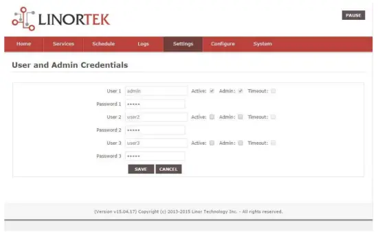
Páxina de credenciais de usuario e administrador
Use this page from the Settings drop down menu. Here you can set up to 3 users for your SERVER system. As a default only User 1 is Active. Here you can:
- User Name and Password – Each user has their own credentials. As a default these are set toadmin/admin, user2/user2 and user3/user3 for Users 1, 2 and 3 respectively. The passwords are never displayed. Nota: when you reset the password, it must be less than 13-character.
- Activo: debe marcarse para que este usuario inicie sesión, non pode desactivar o Usuario 1.
- Administrador: só o administrador pode gardar datos na maioría das páxinas. Isto protexe o teu SERVIDOR de ser modificado por unha persoa non autorizada.
- Tempo de espera: non está activado neste momento.
Páxina Hora/Data
Use esta páxina no menú despregable Configuración. Esta páxina permítelle configurar o sistema de data e hora.
- Time – Set time using an hh:mm:ss format.
- Data: establece a data cun formato aa/mm/dd.
- Time Zone – Set desired time zone 5 for EST, 8 for PST, you can now add a :mm for setting part hour, for example, 5:30 é un fuso horario ás 5 horas e 30 minutos.
- Usar o horario de verán: seleccione para axustar automaticamente a hora do seu sistema o día de verán. (Non é preciso en todos os fusos horarios).
- Usar hora MIL: seleccione para usar o formato de 24 horas.
- Use NTP Update – Select to synchronize SERVER time with NTP server
- NTP Web Sitio: este é o servidor NTP seleccionado para as actualizacións.
- Intervalo NTP: intervalo de tempo entre actualizacións en minutos.
- Log NTP Event – Normally NTP exceptions will be logged, select this option to Log every NTP event. (May be useful in debugging.)

Páxina de configuración
Access this page from the Settings dropdown menu. Select these settings to enable various features in the SERVER
- Use Active Main – No longer used. (Select PAUSE to go inactive.)
- Requirir inicio de sesión: se non se selecciona o SERVIDOR permitirá todo o acceso sen credenciais.
- Use IP Ranges – Not Implemented.
- Use RESTFUL IP Ranges – Not implemented.
- Use Remote IP Ranges – Not implemented.
- Use a autenticación RESTful: esixe nome de usuario e contrasinal para RESTful.
- Ampliar rango de relés: activa 8 relés.
- Usar botóns de radio de relé: se se configura, cando un relé está acendido, todos os demais están desactivados.
- SSL Port No. – Not supported – For future use.
- Usar correos electrónicos do sistema: activa mensaxes de correo electrónico adicionais.
- Usar Fahrenheit: selecciona Celsius ou Fahrenheit.
- PGM Dynamic Relays – Changes properties of relays in task schedule.
- CLR PGMs on Start – Reinitialize tasks on start up.
- RTC Temperature Compensation – All Koda boards can add Temperature and Humidity sensor.
- Use AM2302: use o sensor de temperatura e humidade AM2302 (se vende por separado).
- Java Report – Send data to HourCollector app over ethernet (only for IoTMeter)
- Use Metric – Not supported – For future use.
- UART Usage – Enter “Audio” for Netbell-NTG, “Clock” for Netbell clock.
- Switch Bypass (1/2) – Ignores physical inputs if set. For example, in a Koda 200 board, you want to ignore input 1 switch, check Switch Bypass 1
- Setting 19 – Not supported – For future use
- Usa audio File System – Activate SD Card reader for Netbell-NTG
- WiFi Report – Enable data transfer over WiFi (WiFi IoTMeter only)
- Active Landing Page – Not supported – For future use.
- . Invert Relay Control – The relay is set to NO by default. By checking this box the relay will be inverted to NC.
- Setting 24 – Not supported – For future use.

Páxina DNS dinámica
Access this page from the Configure dropdown menu. From this page you can assign dynamic DNS settings. This page, along with proper port forwarding through the router, can enable global access to a device behind a NAT router or firewall. You will need to assign a static IP address and port number (see Network Config Page on page 25) and port the IP address on your router (refer to your router’s user manual). An internet IP address will have to be hosted in order to access your SERVER from the internet. Currently the only IP hosting service supported is provided by DynDNS (https://dyn.com)
- Usar DDNS: activa este servizo.
- Servizo DDNS: seleccione un servizo no menú desplegable. Actualmente, o único servizo compatible é DynDNS
- Nome de usuario: refírese á conta configurada no servizo DDNS.
- Contrasinal: contrasinal para acceder ao servizo DDNS.
- Host – This is the IP name registered at the DDNS service for rerouting to this SERVER

Páxina de configuración de correo electrónico
Configure unha conta de correo electrónico para que o SERVIDOR utilice para enviar mensaxes de correo electrónico desde varios módulos. Accede a esta páxina desde a pestana Configurar.
Nota: This unit is NOT compatible with SSL/TLS, there are 3rd party SMTP delivery servers which do not require SSL and can be used. For instructions on how to use a 3rd party SMTP delivery service, please refer to Appendix 1 at the end of this manual).
- Servidor SMTP: introduza o servidor de correo de saída que quere utilizar.
- Porto: este é o porto dese servidor. Podes buscar esta información no teu servizo de correo en liña, así como os outros campos configurados.
- Usar SSL: deixalo desmarcado cando uses un servidor SMTP de terceiros.
- Nome de usuario: o nome da súa conta de correo electrónico.
- Contrasinal: contrasinal da conta de correo electrónico.
- To Address – Enter up to 3 address for this email set up. An addressee, a CC and a BC.
- Asunto: liña de asunto da cabeceira do correo electrónico.

Páxina de configuración da rede
Access this page from the Configure dropdown menu. This page allows the configuration of the SERVER’s network settings.
PRECAUCIÓN: Incorrect settings may cause the board to lose network connectivity. In order to access a device in your network remotely you must PORT the device. This tells your router that information coming in should be sent to a specific device on your network.
- MAC Address – This is a unique MAC address that is assigned to this product at time of assembly. It cannot be altered.
- Nome de host: este é un nome de Netbios co que esta unidade pode ser dirixida nalgunhas redes. Tamén pode aparecer no directorio de arrendamento do teu enrutador. Fai un lugar útil para nomear o teu SERVIDOR e aparece na páxina de inicio e no Discoverer.
- Número de porto: pasa a formar parte do enderezo IP e é necesario para o acceso a Internet. Se isto non está configurado, o SERVIDOR por defecto utiliza un número de porto de 80.
- IP Address – Typically you only change the last group of numbers. If you change this IP address make sure to reserve this IP on your router and no other devices are using this IP address or you may not be able to reach this SERVER. If this happens you may need to Restore Defaults using the push button method.
- Pasarela: normalmente un enrutador da túa rede TCP/IP que serve como punto de acceso ao teu ISP.
- Máscara de subrede: un número de 32 bits que enmascara un enderezo IP e divide o enderezo IP en enderezo de rede e enderezo de host. Só déixao no 255.255.255.0
- DNS primario: un DNS primario.
- DNS secundario: un DNS secundario.

Páxina de configuración do intervalo de IP
Access this page from the Configure dropdown menu. Use these security settings to select a range of IP address that will be allowed to access the SERVER.CAUTION: Incorrect settings may cause the board to lose network connectivity. Not implemented on this SERVER.
Páxina de dispositivos remotos
Access this page from the Configure dropdown menu. These settings allow the SERVER to remotely control the relays on another SERVER. This is done by selecting the Remote Device in the Schedule program or by setting up a relay as a REMOTE. There are 8 possible REMOTE locations.
PRECAUCIÓN: A configuración incorrecta fará que a placa perda as súas conexións remotas.
- Nome do dispositivo: introduza un nome de texto para este dispositivo para referencia futura.
- Enderezo IP: o enderezo IP do dispositivo remoto, incluíndo un número de porto.
- Nome de usuario: úsase na autenticación básica.
- Password – Used in Basic Authentication.

Kodalert Page
Not Yet Implemented. Access this page from the Configure dropdown menu. Kodalert provides an interface for alerts of Internet connected devices. Kodalert is a cloud based, open platform monitoring and alert system for the Internet of Things in your physical world. Any Thing that can send an email or TCP messages including our SERVERS, other manufactures devices and people using email can use Kodalert. It can work for multiple remote locations, alert multiple users instantly using the rules you setup by text, email, smart phone Apps push notification or audible alarm instantly when something happens.
- Número de alerta
- Proba
- Use
- Regra
In the Alarm Notification page, you can change the state (on/off) of the relay by clicking the green circle in the state column. Push the EDIT icon to change the Alarm’s settings.

Especificacións
FARGO R8G2
- 10M/100M RJ45 Internet interface with connection and activity LEDs
- 8 Relay outputs, 1FORMC 48 Volt Max (24VAC/DC 3A)
- Status LEDs (pulse, bootloader, and locate)
- Ethernet Bootloader (for server hardware code upgrade)
- PoE or 12VDC @500mA (nominal)
- Web interface w/basic authentication
- On board temperature sensor and voltage sensor
Reset /Locate pushbutton (blue LED) - Working Temperature from 0 to +70 Celsius
- Storage Temperature from 40 to +125 Celsius
- Humidity from 10% to 80% noncondensing
- Dimensions 74mm x 100mm x 20mm, mounting holes 64mm x 92mm Ф 3.2mm 4 places
- Protocolos admitidos: HTTP/SMTP/SNTP
FARGO R4G2
- 10M/100M RJ45 Internet interface with connection and activity LEDs
- 4 1FormC relays 48 Volt Max (24VAC/DC 3A)
- 2 optically isolated digital inputs, 12V 1mA or pulldown switch selectable, 2 conductor screw terminal connectors for each.
- 2 Analog 0-5VDC Inputs 30mA 3.3VDC power source PTC protected. 3 conductor screw terminal connectors for each (3.3VDC, input, ground) (R4ADI only)
- 2 Current sensor inputs. 3.5mm stereo jack connector for each (R4ADI only)
- Status LEDs (pulse, bootloader, and locate)
- Ethernet Bootloader (for server hardware code upgrade
- POE or 12VDC @500mA (nominal)
- Web interface w/basic authentication
- On board temperature sensor and voltage sensor
- Reset/Locate pushbutton
- Working Temperature from 0 to +70 Celsius
- Storage Temperature from 40 to +125 Celsius
- Humidity from 10% to 80% noncondensing
- Dimensions 74mm x 100mm x 20mm, mounting holes 64mm x 92mm Ф 3.2mm 4 places
- Protocolos admitidos: HTTP/SMTP/SNTP
KODA100
- 10M/100M RJ45 Internet interface with connection and activity LEDs
- 2 1-Form-A relay 48VAC@8A Max
- 2 optically isolated digital inputs, 12V 1mA or pulldown switch selectable
- Status LEDs (pulse, bootloader, and locate)
- Ethernet Bootloader (for server hardware code upgrade)
- POE or 12VDC @500mA (nominal)
- Web interface w/basic authentication
- On board temperature sensor and voltage sensor
- Reset/Locate pushbutton (blue LED)
- Working temperature from 0 to +70 Celsius
- Storage temperature from 40 to +125 Celsius
- Humidity from 10% to 80% noncondensing
- Dimensións: 70 mm x 100 mm x 25 mm
- Protocolos admitidos: HTTP/SMTP/SNTP
KOD200
- 10M/100M RJ45 Internet interface with connection and activity LEDs
- 4 1FormA relays 48 Volt Max 1A dry contact or drive 10V ±10% 50mA to external devices
- 2 optically isolated digital inputs, 12V 1mA or pulldown switch selectable
- Status LEDs (pulse, bootloader, and locate)
- Ethernet Bootloader (for server hardware code upgrade)
- POE or 12VDC @500mA (nominal)
- Web interface w/basic authentication
- On board temperature sensor and voltage sensor
- Reset/Locate pushbutton (blue LED)
- Working Temperature from 0 to +70 Celsius
- Storage Temperature from 40 to +125 Celsius
- Humidity from 10% to 80% noncondensing
- Dimensións: 70 mm x 100 mm x 25 mm
- Protocolos admitidos: HTTP/SMTP/SNTP
Disposición de referencia do taboleiro
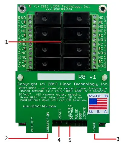
Fargo R8
- 8 Relay outputs, 1FORMC 48 Volt Max (24VAC/DC 3A)
- Conector RJ45
- Conector de alimentación (12VDC)
- Botón de reinicio
- Botón Localizar
Fargo R4
- 3.5mm Inputs for AC Current Sensor (R4ADI Only)
- Analog Inputs (R4ADI Only)
- 4 Relay outputs, 1FORMC 48 Volt Max (24VAC/DC 3A)
- Entradas dixitais
- Digital Input Switches (Input 1 on right.
Up: Pullup, Down: Isolated) - Conector RJ45
- Botón de reinicio
- Botón Localizar
- Conector de alimentación (12VDC)
Koda 100
- Digital Inputs (#1 on the left) 5VDC-48VDC (12VDC-48VDC must use the external resistor)
- Relay Outputs (#1 is on the right) 8A@48VAC Max
- Digital Input Switches (IN 1 on left. UP: Isolated, Down: Pullup)
- Botón de reinicio
- Botón de recarga (acende o LED azul; identifícase no Discoverer)
- Conector RJ45
- Conector de alimentación (12VDC)
- Mini conector USB para sensor de temperatura/humidade (se vende por separado)

Koda 200
- Digital Inputs (#1 on the left) 5VDC-48VDC (12VDC-48VDC must use the external resistor)
- Relay Outputs (#1 is on left) 48 Volt Max 1A dry contact or drive 10V ±10% 50mA
- Digital Input Switches (IN 1 on left. UP: Isolated, Down: Pullup)
- Relay Switches (Up for dry contact, down for 10V/50mA)
- Botón de reinicio
- Botón de recarga (acende o LED azul; identifícase no Discoverer)
- Conector RJ45
- Conector de alimentación (12VDC)
- Mini conector USB para sensor de temperatura/humidade (se vende por separado)

Restablecemento de fábrica
To perform a factory Reset, push the Reset button. When the green LED turns on, push and hold the Reload button until the flashing red LED turns off and then turns on solid. Refer to Board Reference Layout section for the button locations on your device.
This user-manual supplements the documentation for the following Linortek products:
- Netbell-2
- Netbell-8
- Netbell-K (and variants)
- iTrixx-NHM
For more information, documentation and how-to videos, visit https://www.linortek.com/downloads/
Este documento pódese atopar en www.linortek.com/downloads/documentations/
Se precisas axuda co teu dispositivo, visita www.linortek.com/technical-support
Linor Technology, Inc.
Información suxeita a cambios sen previo aviso.
Apéndice 1
Como enviar correos electrónicos SSL usando un servizo SMTP de terceiros para dispositivos Linortek Fargo e Koda
Por defecto, os dispositivos Koda/Fargo usan servidores de correo electrónico SMTP non SSL. Pero a maioría dos servidores de correo electrónico hoxe cambiaron ao protocolo de seguranza SSL, hai servidores de entrega SMTP de terceiros que non requiren SSL e pódense usar. Hai moitos provedores de servizos de correo electrónico SMTP no mercado. Usamos SMTP3GO como example para demostrar o proceso de configuración. SMTP2GO é gratuíto para usar ata 1000 correos electrónicos/mes. Para usar SMTP2GO, visite: https://www.smtp2go.com/ .
Paso 1. Crea a conta SMTP2GO.
Para crear unha conta, só tes que facer clic en "Rexístrate", escoller "1K correos electrónicos" na escala e escoller "Plan gratuíto" (Se precisas enviar máis de 1000 correos electrónicos ao mes, selecciona o plan que cumpra os teus requisitos).

Para crear unha conta en SMTP2GO, será necesario un enderezo de correo electrónico corporativo. O servizo de correo electrónico gratuíto como Gmail ou Yahoo non che permitirá continuar. Despois de activar a súa conta SMTP2GO, cómpre engadir un usuario.
Paso 2. Engade un usuario.
O usuario que crees en SMTP2GO será o servidor de correo de saída cando configures o dispositivo Fargo/Koda para enviar informes por correo electrónico; asegúrate de que o servidor de correo electrónico da túa empresa non bloqueará os correos electrónicos se usas unha conta de correo electrónico gratuíta como Yahoo ou Gmail para engade un usuario aquí.
Inicie sesión na súa conta SMTP2GO, no menú do lado esquerdo, seleccione "Configuración" > "Usuarios SMTP", prema en "Engadir usuario SMTP" e cubra o formulario.
 Despois de engadir o usuario á súa conta SMTP2GO, mostrará a información que precisa para configurar a notificación por correo electrónico nos seus dispositivos Fargo/Koda.

Paso 3. Configura o dispositivo Linortek.
Despois de crear unha conta e engadir un usuario, inicie sesión no seu dispositivo Linortek, navegue ata Configurar - páxina de configuración de correo electrónico para configurar a notificación por correo electrónico:
- Servidor SMTP: introduza o servidor de correo de saída que quere usar, é mail.smtp2go.com no noso example.
- Porto: este é o porto dese servidor. O porto SMTP é 2525 no noso example.
- Usar SSL: deixalo desmarcado cando uses un servidor SMTP de terceiros.
- Nome de usuario: o nome de usuario de SMTP2GO cando creamos un usuario no paso anterior.
- Contrasinal: o contrasinal do usuario de SMTP2GO cando creamos un usuario no paso anterior.
- Enderezo: introduza ata 3 enderezos para esta configuración de correo electrónico. Un destinatario, un CC e un BC.
- Asunto: liña de asunto da cabeceira do correo electrónico.
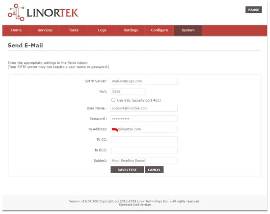
En canto premes "Gardar/Probar", o dispositivo envía automaticamente o correo electrónico de proba. Comprobe lixo/Outro cartafol para atopalo se non está no cartafol da Caixa de entrada.
Paso 4. Establece a tarefa para as notificacións automáticas por correo electrónico.
You should be able to receive email notifications for various events from the Fargo/Koda boards at this point. If you need to receive condition logic notification, you can use our condition logic configuration to setup such report. To setup the logic condition report notification, go to Tasks page on your Fargo/Koda device, click the Edit icon of a Schedule. For details of how to create a logic-based event, please refer to the Set Schedule Page on the Fargo/Koda User Manual, which can be downloaded here:
https://www.linortek.com/download/fargo%20g2_koda%20downloads/fargo%20g2_koda%20documentation/Fargo-G2-and-Koda-User-Manual.pdf
Neste sample Usaremos o dispositivo de contador de horas da rede como example para saber como recibir informes por correo electrónico todos os días ás 11:52.
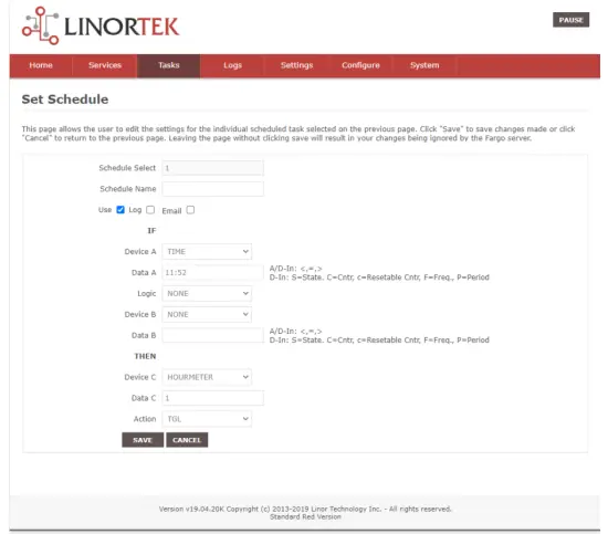
En canto se cumpran todas as condicións da tarefa, recibirá o seguinte correo electrónico:
Hour Reading Report
![]() support@linortek.com
support@linortek.com
Mon 4/11/2022 11:52 AM
To: Liyu Nalven
HM 1, my machine, is at 000242.01 hrs.
Reply Forward
![]()
Documentos/Recursos
 |
LINORTEK Fargo G2 TCP/IP Web Controlador de relés baseado [pdfManual do usuario Fargo G2, Koda, Fargo G2 TCP-IP Web Based Relay Controller, Web Based Relay Controller, Based Relay Controller, Relay Controller |