![]() Fargo G2 and Koda User Manual
Fargo G2 and Koda User Manual
www.linortek.com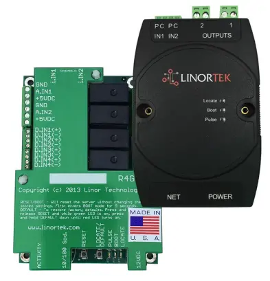 For Fargo G2, Koda
TCP/IP Web Tabanlı Röle Kontrolörü
Rev C 04/2022
Fargo G2 TCP/IP Web Tabanlı Röle Kontrolörü
Thank you for purchasing a Linortek Fargo G2 or Koda TCP/IP Controller. There are many devices that can be controlled by the FARGO/KODA Web Relay Controller. FARGO/KODA Web Controller can be used in such applications as (but not limited to): Lights, security, sprinkler systems, access control, industrial equipment, building automation, HVAC, and many more. Please refer to the Board Reference Layouts on page 29 for input and output specifications on your controller to verify they are suitable to your needs.
Bu kılavuz şunları kapsar:
- FARGO R8 G2
- FARGO R4DI G2
- FARGO R4ADI G2
- KODA100
- KODA200
These will be referred to as SERVER hereafter. When there are differences or additional features they will be noted in the text.
Eğitim videoları, SSS ve teknik destek ekibimizin iletişim bilgileri için lütfen şu adresi ziyaret edin: https://www.linortek.com/technical-support
LINORTEK BİR YIL SINIRLI GARANTİ
Consumer law: For consumers who are covered by consumer protection laws or regulations in their country of residence (“Consumer Law”), the benefits provided in this Linortek One-Year Limited Warranty (“Linortek Limited Warranty”) are in addition to and not instead of the rights provided by Consumer Law and it does not exclude, limit or suspend your rights arising from Consumer Law. You should consult the proper authorities in your country of residence for further information about these rights
Linortek'in bu donanım ürünü (“Ürün”) için garanti yükümlülükleri, aşağıda belirtilen koşullarla sınırlıdır:
Linor Technology, Inc. (“Linortek”) warrants this product against defects in materials and workmanship for a period of ONE (1) YEAR from the date of retail purchase by the original end-user purchaser (“Warranty Period”) when used in accordance with the operating instructions. A copy of a retail receipt is required as proof of purchase. If a hardware defect arises and a valid claim is received within the Warranty Period, at its option and to the extent permitted by law, Linortek will either (1) repair the hardware defect at no charge, using new or refurbished replacement parts, (2) exchange the product with a product that is new or which has been manufactured from new or serviceable used parts and is at least functionally equivalent to the original product, or (3) refund the purchase price of the product. When a refund is given, the product for which the refund is provided must be returned to Linortek and becomes Linortek’s property.
Yukarıdaki garanti, Alıcının (i) derhal yazılı talebine ve (ii) Linortek'e kusurlu olduğu iddia edilen Ürünü inceleme ve test etme fırsatını zamanında sağlamasına tabidir. Söz konusu inceleme Alıcının tesislerinde yapılabilir ve/veya Linortek, masrafları Alıcıya ait olmak üzere Ürünün iadesini talep edebilir. Ancak Linortek, Ürünün iadesiyle bağlantılı paketleme, inceleme veya işçilik maliyetlerinden sorumlu olmayacaktır. Linortek tarafından verilen Ürün İade Yetki numarasının (RMA#) eşlik etmediği hiçbir Ürün garanti hizmeti için kabul edilmeyecektir.
İSTİSNALAR VE SINIRLAMALAR
Bu Sınırlı Garanti, kötüye kullanım, yanlış kullanım, ihmal, yangın veya diğer dış nedenler, kaza, modifikasyonlar, onarımlar veya malzeme ve işçilik kusuru olmayan diğer nedenlerden kaynaklanan hasarları kapsamaz. Linortek tarafından Linortek marka adı ile veya sistem yazılımı dahil ancak bununla sınırlı olmamak üzere dağıtılan yazılım (“Yazılım”) bu Sınırlı Garanti kapsamında değildir. Yazılımla ilgili kullanımınız ve haklarınız, burada bulabileceğiniz Linortek Son Kullanıcı Lisans Sözleşmesine tabidir: https://www.linortek.com/end-user-licenseagreement/. Linortek, ürünün kullanımına ilişkin talimatlara uyulmamasından kaynaklanan hasarlardan sorumlu değildir. Çalıştırma sınırlamalarına uygunluğu sağlamak için Alıcı, [ürünle birlikte verilen] kullanım kılavuzuna başvurmalıdır. Piller Garantiye dahil değildir.
İZİN VERİLEN AZAMİ ÖLÇÜDE, BU SINIRLI GARANTİ VE YUKARIDA BELİRTİLEN ÇÖZÜMLER MÜNHASIRDİR VE DİĞER TÜM GARANTİLERİN, ÇÖZÜMLERİN VE KOŞULLARIN YERİNE GEÇER VE LINORTEK ÖZELLİKLE, SATILABİLİRLİK GARANTİLERİ DAHİL ANCAK BUNLARLA SINIRLI OLMAMAK ÜZERE TÜM YASAL VEYA ZIMNİ GARANTİLERİ REDDEDER. BELİRLİ BİR AMACA UYGUNLUK, İHLAL OLMAMASI. BU GARANTİLER REDDEDİLMEDİĞİ KADAR, BU TÜR GARANTİLERİN TÜMÜ, YASALARIN İZİN VERDİĞİ ÖLÇÜDE, LINORTEK SINIRLI GARANTİSİNİN SÜRESİYLE SINIRLI OLACAK VE ÇÖZÜM, LINORTEK TARAFINDAN BELİRTİLEN ONARIM, DEĞİŞTİRME VEYA İADE İLE SINIRLI OLACAKTIR YALNIZCA KENDİ TAKDİRİNDE. BAZI EYALETLER (ÜLKELER VE İLLER), ZIMNİ GARANTİ VEYA KOŞULLARIN SÜRESİNE İLİŞKİN SINIRLAMALARA İZİN VERMEMEKTEDİR, BU NEDENLE YUKARIDA AÇIKLANAN SINIRLAMALAR SİZİN İÇİN GEÇERLİ OLMAYABİLİR. BU GARANTİ SİZE BELİRLİ YASAL HAKLAR VERİR VE AYRICA EYALETTEN EYALETE (VEYA ÜLKE VEYA BÖLGEYE) DEĞİŞEN BAŞKA HAKLARINIZ DA OLABİLİR. BU SINIRLI GARANTİ AMERİKA BİRLEŞİK DEVLETLERİ YASALARINA GÖRE YÖNETİLİR VE YORUMLANIR.
Sorumluluk reddi beyanları
- Talimatları Okuyun – Ürünü çalıştırmadan önce tüm güvenlik ve çalıştırma talimatlarını okuyun.
- Talimatları Saklayın – İleride başvurmak üzere güvenlik ve çalıştırma talimatlarını saklayın.
- Uyarıları Dikkate Alın – Ürün üzerindeki ve çalıştırma talimatlarındaki tüm uyarılara uyun.
- Talimatları izleyin – Tüm çalıştırma ve kullanım talimatlarını izleyin.
- Temizleme – Temizlemeden önce ürünün fişini prizden çekin. Sıvı ve sprey temizleyici kullanmayın. Reklamı kullanamp sadece muhafazayı temizlemek için bez.
- Ekler – Linortek tarafından özellikle tavsiye edilmedikçe ekleri kullanmayın. Uyumsuz veya uygun olmayan eklerin kullanılması tehlikeli olabilir.
- Aksesuarlar – Bu ürünü dengesiz bir stand, tripod, braket veya montaj parçası üzerine yerleştirmeyin. Ürün düşebilir ve bir kişinin ciddi şekilde yaralanmasına ve üründe ciddi hasara neden olabilir. Yalnızca üretici tarafından önerilen veya ürünle birlikte satılan bir stand, tripod, braket veya montaj parçası ile kullanın. Ürünü monte ederken üreticinin talimatlarını izleyin ve yalnızca üretici tarafından önerilen montaj aksesuarlarını kullanın. Bir cihaz ve araba kombinasyonunu kullanırken dikkatli olun. Ani duruşlar, aşırı güç ve düz olmayan yüzeyler, cihaz ve araba kombinasyonunun devrilmesine neden olabilir.
- Havalandırma – Varsa, mahfazadaki açıklıklar havalandırma için ve ürünün güvenilir şekilde çalışmasını sağlamak ve aşırı ısınmadan korumak için sağlanmıştır. Bu açıklıkları kapatmayın veya kapatmayın. Uygun havalandırma sağlanmadıkça veya Linortek'in talimatlarına uyulmadıkça bu ürünü yerleşik bir kuruluma yerleştirmeyin.
- Güç Kaynakları – Bu ürünü yalnızca kullanım kılavuzunda veya ürün etiketinde belirtilen güç kaynağı türüyle çalıştırın.
Kullanmayı planladığınız güç kaynağı türünden emin değilseniz, cihaz satıcınıza veya yerel elektrik şirketine danışın; ancak kullanım kılavuzunda veya işaret etiketinde belirtilenin dışında herhangi bir güç kaynağı türünün kullanılması her türlü garantiyi geçersiz kılacaktır. Pil gücüyle veya diğer kaynaklardan çalıştırılması amaçlanan ürünler için [ürünle birlikte verilen] çalıştırma talimatlarına bakın. - Topraklama veya Polarizasyon – Bu ürün, polarize bir alternatif akım hattı fişiyle (bir ucu diğerinden daha geniş olan bir fiş) donatılmış olabilir. Bu fiş elektrik prizine yalnızca tek yönde takılacaktır. Bu bir güvenlik özelliğidir. Fişi prize tam olarak takamıyorsanız, fişi ters çevirmeyi deneyin. Fiş hala yerine oturmuyorsa bunun nedeni prizinizin fişle uyumlu olmamasıdır. Prizinizi uyumlu bir prizle değiştirmek için elektrikçinizle iletişime geçin. Fişi uyumsuz bir prize takmaya zorlamayın veya başka bir şekilde fişin güvenlik amacını ortadan kaldırmaya çalışmayın. Alternatif olarak bu ürün, üçüncü (topraklama) pini olan 3 telli topraklama tipi bir fişle donatılabilir. Bu fiş yalnızca topraklama tipi elektrik prizine takılabilir. Bu bir güvenlik özelliğidir. Fişi uyumsuz bir prize takmaya zorlamayın veya başka bir şekilde fişin güvenlik amacını ortadan kaldırmaya çalışmayın. Priziniz fişle uyumlu değilse prizinizi uyumlu bir prizle değiştirmek için elektrikçinizle iletişime geçin.
- Güç Kablosu Koruması – Güç kaynağı kablolarını, üzerine basılmayacak veya üzerlerine veya karşılarına konulan nesneler tarafından sıkıştırılmayacak şekilde yönlendirin, kablolara ve fişlere, uygun prizlere ve kabloların cihazdan çıktığı noktalara özellikle dikkat edin. .
- Elektrik Hatları – Bir dış mekan sistemini havai elektrik hatlarının veya diğer elektrik ışıklarının veya güç devrelerinin yakınına veya bu tür elektrik hatlarına veya devrelerine düşebileceği yerlere yerleştirmeyin. Bir dış mekan sistemi kurarken, bu tür elektrik hatlarına veya devrelerine dokunmamaya çok dikkat edin, çünkü bunlarla temas ölümcül olabilir.
- Aşırı Yükleme – Yangına veya elektrik çarpmasına neden olabileceğinden, prizleri ve uzatma kablolarını aşırı yüklemeyin.
- Nesne ve Sıvı Girişi – Tehlikeli sıvılara temas edebileceğinden, bu ürünün açıklıklarından asla herhangi bir nesneyi içeri itmeyin.tagYangına veya elektrik çarpmasına neden olabilecek noktalar veya kısa devre yapan parçalar. Ürünün üzerine asla herhangi bir sıvı dökmeyiniz.
- Servis – Kapakları açmak veya çıkarmak sizi tehlikeli volümlere maruz bırakabileceğinden, bu ürüne kendiniz servis vermeye çalışmayın.tage veya diğer tehlikeler. Ürünün tüm servis işlemlerini Linortek'e yönlendirin.
- Servis Gerektiren Hasar – Aşağıdaki koşullarda ürünün fişini prizden çekin ve servis için Linortek Müşteri Desteğine başvurun:
a. Güç kaynağı kablosu veya fişi hasar gördüğünde.
b. Ürünün üzerine sıvı döküldüyse veya nesneler düştüyse.
c. Ürün yağmura veya suya maruz kalmışsa.
d. Ürün, [ürünle birlikte verilen] çalıştırma talimatlarını izleyerek normal şekilde çalışmıyorsa. Diğer kontrollerin yanlış ayarlanması hasara yol açabileceğinden ve genellikle ürünü normal çalışmasına geri döndürmek için kalifiye bir teknisyen tarafından kapsamlı bir çalışma gerektireceğinden, yalnızca çalıştırma talimatlarının kapsadığı kontrolleri ayarlayın.
e. Ürün düşürüldüyse veya kabin hasar gördüyse.
F. Ürün performansında belirgin bir değişiklik gösteriyorsa. - Yedek Parçalar – Yedek parça gerekiyorsa, Düşük Hacimlitage Elektrikçi bunları yalnızca üretici tarafından belirtilen parçayı kullanarak değiştirin. Yetkisiz değiştirmeler yangına, elektrik çarpmasına veya diğer tehlikelere neden olabilir. Yedek parçalar şu adreste bulunabilir: https://www.linortek.com/store/
- Güvenlik Kontrolü – Bu ürüne herhangi bir servis veya onarım işlemi tamamlandıktan sonra, servis teknisyeninden ürünün düzgün çalışma koşullarında olduğunu belirlemek için güvenlik kontrolleri yapmasını isteyin.
- Koaks Topraklama – Ürüne bir dış kablo sistemi bağlıysa, kablo sisteminin topraklandığından emin olun. Yalnızca ABD modelleri – Ulusal Elektrik Yasası, ANSI/NFPA No.810-70, Bölüm 1981, montaj ve destek yapısının uygun şekilde topraklanması, koaksın bir deşarj ürününe topraklanması, topraklama iletkenlerinin boyutu, konum hakkında bilgi sağlar. deşarj ürünü, topraklama elektrotlarına bağlantı ve topraklama elektrotu gereksinimleri.
- Yıldırım – Bu ürünün şimşekli havalarda daha fazla korunması için veya uzun süre boyunca kullanılmadan ve gözetimsiz bırakılmadan önce, fişini duvar prizinden çekin ve kablo sistemini ayırın. Bu, yıldırım ve güç hattı dalgalanmaları nedeniyle ürüne zarar gelmesini önleyecektir.
- Dış Mekan Kullanımı – Bu ürün su geçirmez değildir ve ıslanmasına izin verilmemelidir. Yağmura veya diğer sıvı türlerine maruz bırakmayın.
Yoğuşma oluşabileceğinden gece boyunca açık havada bırakmayın. - Pilleri, sigortaları değiştirirken veya kart seviyesindeki bir ürünü tutarken elektronik cihazlara zarar verebilecek elektrostatik boşalmaya dikkat edin. Topraklanmış bir elektronik servis tezgahı kullanmak en iyisidir. Bu yoksa metal bir alete veya boruya dokunarak kendinizi boşaltabilirsiniz. Pilleri veya sigortaları değiştirirken i) pil kabloları dışındaki kablolara ve ii) baskılı devre kartına dokunmayın.
SORUMLULUĞUN SINIRLANDIRILMASI
IN NO EVENT WILL LINOR TECHNOLOGY BE LIABLE, WHETHER IN CONTRACT, TORT, OR OTHERWISE, FOR ANY INCIDENTAL, SPECIAL, INDIRECT, CONSEQUENTIAL OR PUNITIVE DAMAGES, INCLUDING, BUT NOT LIMITED TO, DAMAGES FOR ANY LOSS OF USE, LOSS OF TIME, INCONVENIENCE, COMMERCIAL LOSS, OR LOST PROFITS, SAVINGS, OR REVENUES TO THE FULL EXTENT SUCH MAY BE DISCLAIMED BY LAW. DISCLAIMER FOR CRITICAL APPLICATIONS
Bu ürün, yaşam destek ürünü veya bir arızanın kişisel yaralanma veya ölüme neden olabileceği diğer kullanımlar için tasarlanmamıştır veya yetkilendirilmemiştir. Siz veya müşterileriniz bu ürünü bu tür istenmeyen veya yetkisiz kullanımlar için kullanır veya kullanımına izin verirseniz, Linor Technology'yi ve bağlı şirketlerini ve her birinin memurlarını, çalışanlarını ve distribütörlerini bu tür kullanımla ilgili tüm sorumluluklardan tamamen tazmin etmeyi kabul edersiniz. avukat ücretleri ve masrafları.
KULLANIM SINIRLAMASI İÇİN EK BİLDİRİM
Özel olarak belirtilmediği sürece, Ürünlerimiz hat volümünü değiştirmek için TASARLANMAMIŞTIR.tage (110V ve üzeri) cihazlar. Hat hacminde çalışan cihazı kontrol etmek içintagkalifiye bir elektrikçi röle gibi bir aracı cihaz KURMALIDIR. Kontrol edilecek cihazları seçerken, düşük volüm seçmek en iyisidir.tag24VAC solenoidden su akışına kontrol gibi kontroller. Sadece kalifiye elektrikçiler bir hat voltage cihaz. Ek olarak, kablo ölçüsü boyutu ve uygun muhafaza dahil ancak bunlarla sınırlı olmamak üzere yerel yasalara uyulmalıdır. Linortek, Ürünlerimizin uygunsuz kullanımı nedeniyle kullanıcıya veya üçüncü şahıslara verilen zararlardan sorumlu değildir. Bu sorumluluk kullanıcıya aittir. Linortek, Ürünlerimizin uygunsuz kullanımından kaynaklanan cihaz hasarlarından sorumlu değildir.
RÖLE SESTAGE ÖZELLİKLERİ
Cihazları elektrik devrelerine veya diğer ekipmanlara bağlarken lütfen dikkatli olun. Bu web denetleyici herhangi bir vol'a bağlanmak için TASARLANMAMIŞTIRtage greater than 48V. Utilizing this arrangement, should allow you to virtually control anything. It is important that you use licensed electricians and comply with electrical codes that are applicable to your location. These codes exist for your safety, as well as the safety of others. Linortek assumes no responsibility for any harm or damage resulting from a failure adhere to local laws, ordinances or regulations or failure to follow specified instructions for installation and product usage.
Linortek Yazılım ve Belgeleri için Son Kullanıcı Lisans Sözleşmesi
Bu Son Kullanıcı Lisans Sözleşmesi (“EULA”), SİZ (bireysel veya tek bir kuruluş) ile Linor Technology, Inc. (“Linortek” veya “biz” veya “bize”) arasında, yazılımı kullanımınızı yöneten yasal bir sözleşmedir. ve Fargo, Koda, Netbell, IoTMeter ve iTrixx serisi ürünlere (“Linortek Ürünleri”) gömülü veya bunlarla ilişkili belgeler (“Yazılım”).
Bu EULA, Linortek'i kullanımınızı düzenlemez. websitesi veya Linortek Ürünleri (Yazılım hariç). Linortek kullanımınız website Linortek tarafından yönetilmektedir website hizmet şartları ve Linortek gizlilik politikası şu adreste bulunabilir:
http://www.linortek.com/terms-and-conditions [Linortek Ürünlerini (Yazılım hariç) satın alma işleminiz, adresinde bulunabilecek Linortek sınırlı garantisine tabidir. https://www.linortek.com/linortek-one-year-limited-warranty/
This EULA governs your access and use of the Software. This EULA gives you specific legal rights, and you may also have other legal rights in addition, which vary from jurisdiction to jurisdiction. The disclaimers, exclusions, and limitations of liability under
this EULA will not apply to the extent prohibited or limited by applicable law. Some jurisdictions do not allow the exclusion of implied warranties or the exclusion or limitation of incidental or consequential damages or other rights, so those provisions of this EULA may not apply to you.
Yazılımı veya belgeleri kurarak, erişerek, kopyalayarak ve/veya kullanarak, bu EULA'nın hüküm ve koşullarına kendiniz veya bu tür kurulum, erişim, kopyalama ve/veya bu tür kurulum, erişim, kopyalama ve/veya temsil ettiğiniz tüzel kişi adına bağlı olmayı kabul ediyorsunuz. kullanmak. (i) kendiniz veya temsil ettiğiniz tüzel kişi adına bu EULA'nın şartlarını kabul etme ve kabul etme hakkına, yetkisine ve kapasiteye sahip olduğunuzu (ii) ikamet ettiğiniz yargı bölgesinde yeterli yasal yaşta olduğunuzu beyan ve garanti edersiniz. , (iii) ABD Hükümeti ambargosuna tabi olan veya ABD Hükümeti tarafından “teröristleri destekleyen” bir ülke olarak belirlenmiş bir ülkede bulunmuyorsunuz; ve (ii) ABD Hükümeti'nin yasaklanmış veya kısıtlanmış taraflar listesinde yer almamış olmanız.
Bu EULA'nın koşullarına bağlı kalmak istemiyorsanız, Yazılımı hiçbir şekilde kuramaz, erişemez, kopyalayamaz veya kullanamazsınız (satın aldığınız bir cihaza önceden kurulmuş olsun veya olmasın).
- Yazılımın/Yazılım Lisansının İzin Verilen Kullanımı.
Bu EULA'nın koşullarına tabi olarak, Linortek size (a) Yazılımın bir kopyasını yürütülebilir nesne kodu biçiminde indirmek, kurmak ve yürütmek için sınırlı, geri alınabilir, münhasır olmayan, alt lisansı verilemeyen, devredilemez bir hak ve lisans verir. yalnızca, yalnızca sahip olduğunuz veya kontrol ettiğiniz Linortek Ürünü üzerinde ve (b) Yazılımı yalnızca Linortek Ürünü ile bağlantılı olarak, Linortek'te açıklanan kullanım amacına uygun olarak kullanmak. website (1(a) ve 1(b)'nin her biri bir "İzin Verilen Kullanım" ve toplu olarak "İzin Verilen Kullanımlar"). - Yazılımı Kullanımınıza İlişkin Kısıtlamalar.
Yazılımı, yukarıdaki Bölüm 1'de açıklanan İzin Verilen Kullanımlar dışında herhangi bir amaçla kullanmamayı ve başkalarının kullanmasına izin vermemeyi kabul etmektesiniz. Bu, diğer şeylerin yanı sıra şunları yapamayacağınız anlamına gelir:
(a) Yazılımın herhangi bir bölümünü düzenlemek, değiştirmek, değiştirmek, uyarlamak, tercüme etmek, türevlerini yapmak, parçalarına ayırmak, tersine mühendislik yapmak veya tersine derlemek (geçerli yasaların birlikte çalışabilirlik amacıyla bu tür kısıtlamaları özel olarak yasakladığı durumlar hariç, bu durumda kabul etmektesiniz). önce Linortek ile iletişime geçmek ve Linortek'e birlikte çalışabilirlik amaçları için gerekli olan değişiklikleri yaratma fırsatı sağlamak);
(b) Yazılımı herhangi bir ticari amaç için lisanslamak, atamak, dağıtmak, iletmek, satmak, kiralamak, barındırmak, dış kaynak kullanmak, ifşa etmek veya başka bir şekilde kullanmak veya Yazılımı herhangi bir üçüncü tarafın kullanımına sunmak;
(c) herhangi bir üçüncü şahsın Yazılımı herhangi bir üçüncü şahsın adına veya yararına kullanmasına izin vermek;
(d) Yazılımın herhangi bir bölümünü sahip olduğunuz veya kontrol ettiğiniz Linortek Ürünü dışındaki herhangi bir cihaz veya bilgisayarda kullanmak;
(e) Yazılımı herhangi bir geçerli yerel, ulusal veya uluslararası yasayı ihlal edecek şekilde kullanmak; veya
(f) remove or alter any labels, symbols, legends or proprietary notices, including but not limited to any copyright, trademark, logo in the Software. You may not disclose the results of any performance or functional evaluation of anyof the Software to any third party without the prior written consent of Linortek for each such release. - Güncellemeler.
Linortek, Yazılımın performansını iyileştirmek için zaman zaman güncellemeler, yükseltmeler, yamalar, hata düzeltmeleri ve diğer değişiklikleri (“Güncellemeler”) geliştirebilir. Linortek'te aksi belirtilmedikçe websitesinde, bu Güncellemeler size ücretsiz olarak sağlanacaktır. Bu Güncellemeler size haber verilmeden otomatik olarak yüklenebilir. Yazılımı kullanarak, otomatik Güncellemelere de izin vermiş olursunuz. Bunu kabul etmiyorsanız, Yazılımı hiçbir şekilde kuramaz, erişemez, kopyalayamaz veya kullanamazsınız. - Sahiplik.
The Software is licensed to you and not sold. Linortek reserves all rights to the Software and any Updates not expressly granted herein. The Software and Linortek Products are protected by copyright, trademark and other intellectual property laws andtreaties. Linortek and its licensors own the title, copyright, trademarks and other intellectual property rights in the Software.
You are not granted any rights to Linortek’s trademarks or service marks. There are no implied licenses in this EULA. - Fesih.
This EULA is effective from the date you first use the Software and will continue for as long as you own the Linortek Product associated with it or until you or Linortek terminate this agreement under this section. You may terminate this EULA at any time upon written notice to Linortek at the address provided below. Linortek may terminate this EULA at any time if you fail to comply with any of the terms in this agreement. The license granted in this EULA terminates immediately when the agreement terminates. Upon termination, you must stop using the Linortek Product and the Software and you must delete all copies of the
Software. The terms of Sections 2 will still remain in effect after the agreement terminates. - Garanti feragatnamesi.
EXTENT PERMITTED BY APPLICABLE LAW, LINORTEK PROVIDES THE SOFTWARE “AS-IS” AND DISCLAIMS ALL WARRANTIES AND CONDITIONS, WHETHER EXPRESS, IMPLIED, OR STATUTORY, INCLUDING THE WARRANTIES OF MERCHANTABILITY, FITNESS FOR A PARTICULAR PURPOSE, TITLE, QUIET ENJOYMENT, ACCURACY, AND NON-INFRINGEMENT OF THIRD-PARTY RIGHTS. LINORTEK DOES NOT GUARANTEE ANY SPECIFIC RESULTS FROM THE USE OF THE SOFTWARE. LINORTEK MAKES NO WARRANTY THAT THE SOFTWARE WILL BE UNINTERRUPTED, FREE OF VIRUSES OR OTHER HARMFUL CODE, TIMELY, SECURE, OR ERROR-FREE. YOU USE THE SOFTWARE AND THE LINORTEK PRODUCT AT YOUR OWN DISCRETION AND RISK. YOU WILL BE SOLELY RESPONSIBLE FOR (AND LINORTEK DISCLAIMS) ANY AND ALL LOSS, LIABILITY, OR DAMAGES RESULTING FROM YOUR USE OF THE SOFTWARE
AND LINORTEK PRODUCT. - Sorumluluğun Sınırlandırılması.
Bu EULA'daki ve özellikle bu "Sorumluluğun Sınırlandırılması" maddesindeki hiçbir şey, yürürlükteki yasalar kapsamında hariç tutulamayacak sorumluluğu hariç tutmaya çalışmayacaktır.
YUKARIDAKİ GARANTİ SORUMLULUK REDDİLERİNE EK OLARAK, GEÇERLİ YASALARIN İZİN VERDİĞİ MAKSİMUM ÖLÇÜDE, (A) LINORTEK HİÇBİR ŞEKİLDE DOLAYLI, ÖRNEK OLARAK, ÖZEL VEYA ARIZİ ZARARLARDAN SORUMLU OLMAYACAKTIR. ÜRÜNLER VEYA YAZILIMLARLA İLGİLİ VEYA İLGİLİ OLARAK, LINORTEK BU TÜR ZARARLARIN OLASILIĞINI BİLMİŞ OLSA VEYA BİLMESİ GEREKTİĞİNDE VE (B) LINORTEK'İN ÜRÜNLER VE YAZILIMLARLA İLGİLİ VEYA BAŞKA OLARAK KAYNAKLANAN TOPLAM YÜKÜMLÜLÜĞÜ ÖNCEKİ 6 AY İÇERİSİNDE LINORTEK VE LINORTEK'İN YETKİLİ ÜRÜN VEYA HİZMETLER İÇİN SATIŞ TEMSİLCİLERİNE VEYA SATIŞ TEMSİLCİLERİNE GERÇEKTE ÖDEDİĞİNİZ TUTARI ASLA AŞMAYACAK BİR MİKTARLA SINIRLI OLACAKTIR (varsa). BU SINIRLAMA KÜMÜLATİFTİR VE BİRDEN FAZLA OLAY VEYA İDDİANIN MEVCUT OLMASI İLE ARTTIRILMAYACAKTIR. LINORTEK, HER TÜRLÜ LINORTEK'İN LİSANS VERENLERİNİN VE TEDARİKÇİLERİNİN HER TÜRLÜ SORUMLULUĞUNU REDDEDER. - İhracat Yasalarına Uyum.
Yazılımın ve ilgili teknolojinin ABD ihracat kontrol yasalarına, ABD ihracat yargısına tabi olduğunu ve diğer ülkelerdeki ihracat veya ithalat düzenlemelerine tabi olabileceğini kabul edersiniz. ABD İhracat İdaresi Düzenlemeleri'nin yanı sıra ABD ve diğer hükümetler tarafından yayınlanan son kullanıcı, son kullanım ve varış noktası kısıtlamaları da dahil olmak üzere, Yazılım için geçerli olan tüm uluslararası ve ulusal yasa ve düzenlemelere kesinlikle uymayı kabul edersiniz. Gerektiğinde Yazılımı ve ilgili teknolojiyi ihraç etmek, yeniden ihraç etmek veya ithal etmek için yetki alma sorumluluğunun size ait olduğunu kabul edersiniz.
Bu bölüm kapsamındaki yükümlülüklerinizi ihlal etmenizden kaynaklanan veya bununla ilgili her türlü talep, kayıp, yükümlülük, zarar, para cezası, ceza, maliyet ve harcamaya (avukat ücretleri dahil) karşı Linortek'i tazmin edecek ve masun tutacaksınız. - Atama.
Bu EULA kapsamındaki haklarınızın veya yükümlülüklerinizin hiçbirini devredemezsiniz ve herhangi bir atama girişimi geçersiz ve etkisiz olacaktır. - Duyurular.
Linortek, Linortek'e kaydolurken verdiğiniz e-posta ve adresi kullanarak bu EULA ile ilgili herhangi bir bildirimde bulunabilir. - Feragat
Geçerli olması için, Linortek tarafından işbu Sözleşme kapsamındaki tüm feragatler yazılı olmalı ve yetkili bir Linortek temsilcisi tarafından imzalanmalıdır. Linortek'in işbu Sözleşme kapsamındaki herhangi bir şartı yerine getirmedeki diğer herhangi bir başarısızlığı, bir feragat olarak kabul edilmeyecektir. - Bölünebilirlik.
Bu EULA'nın uygulanamaz olduğu tespit edilen herhangi bir hükmü, yürürlükteki yasa kapsamında mümkün olan en geniş ölçüde bu hükmün amaçlarına ulaşmak için düzenlenecek ve yorumlanacak ve kalan tüm hükümler tam olarak yürürlükte ve yürürlükte kalacaktır. - Geçerli Kanun; mekan.
You agree that this EULA, and any claim, dispute, action, cause of action, issue, or request for relief arising out of or relating to this EULA, will be governed by the laws of the state of North Carolina, U.S.A., without regard to conflicts of laws principles, provided that if you reside in a country that will not apply U.S. law to disputes related to these terms, then the laws of your country will apply. You also agree that the United Nations Convention on Contracts for the International Sale of Goods shall not
apply. You agree that regardless of any statute or law to the contrary, any cause of action against us arising out of or related to the Linortek webSite, Yazılım veya Linortek Ürünleri, dava nedeninin ortaya çıkmasından sonraki bir (1) yıl içinde başlamalıdır veya bu tür dava nedeni kalıcı olarak engellenecektir. Bu EULA ile ilgili herhangi bir dava veya kovuşturma, Raleigh, Kuzey Carolina'da bulunan bir federal veya eyalet mahkemesine getirilmelidir ve her bir taraf, Linortek'in ihtiyati tedbir talep etmesi dışında, bu tür herhangi bir iddia veya anlaşmazlıkta bu tür herhangi bir mahkemenin yargı yetkisine ve yerine gayri kabili rücu olarak kabul eder. fikri mülkiyetini korumak için yargı yetkisine sahip herhangi bir mahkemede rahatlama. - Kaliforniya Önerisi 65 Uyarısı.
 UYARI: Bu ürün sizi Kaliforniya Eyaleti tarafından kansere neden olduğu bilinen kurşun dahil kimyasallara maruz bırakabilir. Daha fazla bilgi için www.P65Warnings.ca.gov adresine gidin.
Başlarken
The Fargo SERVER is what is called a “bare board” product and is supplied without a housing. It operates on low voltage; however you need to use simple handling precautions to prevent damage to the circuits. All electronics are susceptible to electrostatic discharge. This high voltage “shock” can permanently damage your device. Before handling the product, you should touch a surface such as a grounded workbench or table. It is also best to handle the device from its edges. If you notice that your chair or clothes often cause static discharges, you must exercise extra caution. The unit is supplied with four rubber feet which keeps the bottom of the board from coming into contact with the surface you put it on. Be careful not to let metal objects, such as screw drivers or hardware, come in contact with the bottom of this product. The board can be mounted on a panel using stand offs and #4 hardware. The mounting holes are connected to the GROUND signal. The SERVER unit is a self-contained web server configured with various input and output circuits. Although the relays are rated for higher voltages, bu ürün hat hacminde kullanılmak üzere tasarlanmamıştır.tages. You should never use voltages through the SERVER product exceeding 48 volts. IT IS NOT SAFE.
The KODA SERVER is a housed unit with a DIN rail mountable enclosure that can be snapped onto a DIN rail or attached to any flat surface such as a wall or under a counter. KODA 100 has two relays (48VAC@1A), KODA 200 has four relays which can drive 10V 50mA to external devices. The unit is supplied with a DIN Rail mountable enclosure with removable terminal connectors for easy installation. The KODA SERVER can be mounted on a panel or on the wall using the DIN rail mount clip. The removable wire terminal connectors simplify field installation and allow for easy troubleshooting and maintenance: the unit can be removed from the system without disturbing the system wiring.
Sunucuyu Kablolama
Not: For a diagram showing the location of all connectors on your SERVER referenced in this section, please see the section – Board Layout Reference.
Dikkat: Bu birimler yerden izole edilmiştir. Her zaman güç döngüsü yalnızca SUNUCU ünitesine bağlanacak şekilde bağlayın.
Harici toprak bağlantıları KULLANMAYIN. Bunu yapmak SUNUCU veya POE kaynaklı cihaza zarar verebilir.
- Place the unit on a table or bench being careful not to let any metal objects come into contact with the bottom of the circuit board (Fargo Only).
- Connect the 12VDC power supply to a suitable AC outlet and plug the barrel connector into the SERVER at the location labelled “12VDC/POWER”. Alternatively, you may also use POE. At this point the GREEN/Boot LED should come on and start flashing indicating the SERVER is operating and is in the “Bootload Mode”. This mode allows the user to update the server software that is used on the unit. After about 5 seconds, the GREEN LED will go off and the RED LED will start blinking once per second indicating the SERVER is operating in “Server Mode” and is accessible on a network utilizing TCP/IP protocols.
DİKKAT: POE AĞ ANAHTARINI KULLANDIĞINIZDA, 12VDC GÜÇ KAYNAĞINI AYNI ZAMANDA SUNUCUYA GÜÇ VERMEK İÇİN KULLANMAYIN, KART'A ZARAR VERİR. - Plug an Ethernet cable into the RJ45/NET connector. The “Connection” LED will come on if a 100MHz network is available, otherwise it will remain off and the “Activity” LED should start blinking indicating network activity. Fargo G2 Relay Connections
There are 8 relays on the FARGO R8 and 4 on the FARGO R4. These are dry contact relays. These units are designed for only low voltage kontrolü ve ses seviyesi olmamalıdırtage applied to the relay greater than 48 volts. This is for your safety as well as to stay within the parameters of the parts and circuit board design. The relays have 3 terminals labelled NO, C and NC which stand for Normally Open, Common and Normally Closed. When activated, the relay moves the connection from CNC to CNO. If you want to make a connection when the relay is activated, connect your wires between C and NO. When the relay is activated C and NO will be connected together. If you want to break a circuit when the relay is activated, make your connections to C and NC. When the relay is activated the circuit will be broken (or open)
Koda Relay Connection
There are 2 relays on the KODA 100. The KODA 100 has 2 removable 2 position connectors (1 for each relay) and are simply numbered “1” and “2”. These relays are normally open.
There are 4 relays on the KODA 200. The KODA 200 has 1 removable 8 position connector. Each relay has a “+” connection and a numbered connection. The relays may be set to supply about 10VDC by selecting “+V” on the setting switch (see Board Layout Reference page 29) or set to dry contact DC on the switch. If “+V” is selected then the voltage will be present on the “+” terminal and the numbered terminal is the return. Otherwise, a normally open dry contact exists across the “+” and numbered connection. KODA 100/200 is designed for only low voltage kontrolü ve ses seviyesi olmamalıdırtagRöleye 48 volttan daha büyük bir gerilim uygulandı. Bu hem güvenliğiniz hem de parça ve devre kartı tasarımı parametreleri dahilinde kalmanız içindir.

![]() LINOR TECHNOLOGY HİÇBİR DURUMDA SÖZLEŞMEDE, HAKSIZ OLDUĞU YA DA BAŞKA BİR ŞEKİLDE, HERHANGİ BİR TESADÜFİ, ÖZEL, DOLAYLI, DOLAYLI VEYA CEZAİ ZARARLARDAN, HİÇBİR ZAMAN KAYBI, ZARARLAR, HİÇBİR ZAMAN ZARARLARI DAHİL ANCAK BUNLARLA SINIRLI OLMAMAK ÜZERE SORUMLU OLMAYACAKTIR. , TİCARİ KAYIP YA DA KAR, TASARRUF YA DA GELİRLERİN TAM ÖLÇÜDE KAYIPLARI KANUN TARAFINDAN REDDEDİLEBİLİR.
LINOR TECHNOLOGY HİÇBİR DURUMDA SÖZLEŞMEDE, HAKSIZ OLDUĞU YA DA BAŞKA BİR ŞEKİLDE, HERHANGİ BİR TESADÜFİ, ÖZEL, DOLAYLI, DOLAYLI VEYA CEZAİ ZARARLARDAN, HİÇBİR ZAMAN KAYBI, ZARARLAR, HİÇBİR ZAMAN ZARARLARI DAHİL ANCAK BUNLARLA SINIRLI OLMAMAK ÜZERE SORUMLU OLMAYACAKTIR. , TİCARİ KAYIP YA DA KAR, TASARRUF YA DA GELİRLERİN TAM ÖLÇÜDE KAYIPLARI KANUN TARAFINDAN REDDEDİLEBİLİR.
KULLANIM SINIRLAMASI İÇİN EK BİLDİRİM
Özel olarak belirtilmediği sürece, bu ürün hat volümünü değiştirmek için TASARLANMAMIŞTIR.tage cihazlar. Bu sınırlama, tüm FARGO AND KODA ürünlerini içerir. Hat hacminde çalışan cihazı kontrol etmek içintagkullanıcının röle gibi bir aracı cihaz kurması ZORUNLUDUR.
Bir hat vol bağlarkentage aracı cihaz kullanan cihaz, ya kalifiye bir elektrikçi olmalısınız ya da kalifiye bir elektrikçinin hizmetlerini kullanmalısınız. Ek olarak, kablo ölçüsü boyutu ve uygun muhafaza dahil ancak bunlarla sınırlı olmamak üzere yerel yasalara uyulmalıdır.
Linortek cannot assume any responsibility for harm to the user or third parties for improperly using our Fargo/Koda products. This liability remains with the user. Linortek cannot assume any responsibility for damage to the device for improperly using our SERVER product.
For relay specifications, please see Board Reference Layout page 29
Digital Input Connections (Fargo R4 and Koda)
The digital inputs allow the SERVER to detect an external on/off state of a sensor. With this information the SERVER can display whether an input is on or off, count events in a resettable or non-resettable counter, and calculate the frequency (such as for use as a tachometer) or the period of the input. There are two modes of operation for the digital inputs – PULL UP and ISOLATED.
a) PULL UP mode connects a 1K resistor to an internal voltage terminal 1 ve 2 arasında basit bir anahtar (manyetik kapı anahtarı gibi) kullanmanıza olanak tanır. Bu, anahtar etkinleştirildiğinde girişe bir sinyal gönderilir.
b) ISOLATED mode allows you to directly drive the SERVER’s optoisolator with an external voltage dahili bir 1K direnç olsa da. bu cilttagOptoizolatör diyota minimum 5mA veya maksimum 24mA sağlayan 2V ila 30V aralığında olabilir. Bu ciltle başka dahili bağlantı yoktage so it is an isolated input. Please note, when connecting a 12VDC-¬24VDC circuit to the input, an external resistor (can be provided at request, 2.2k ohm 0.5watt) must be used.
These modes are selected by the switch on the SERVER (see Board Layout Reference page 29) marked ISO and PU for isolated and pull up respectively. These are set at the factory to ISO by default.
Wiring a push button: For distances up to 500 feet, a 20 AWG shielded wire is suitable for wiring a push button. If the distance between the push button and the controller extends up to 5,000 feet, use a 16 AWG shielded cable instead. Keep in mind that longer cable runs are more susceptible to signal interference.
Dikkat: If you intend to use isolated mode, verify that the input switch is set to ISO before applying an external voltage. Aksi takdirde SUNUCU veya POE kaynaklı cihaz zarar görebilir.
Analog Input Connections (Fargo R4ADI)
The analog inputs allow the SERVER to read the value of external equipment. There are 2 analog inputs.
For AC current monitoring, use one of the two 3.5mm stereo inputs to interface with a current sensor.
2 analog giriş terminal bloğu, sıcaklık veya basınç sensörleri gibi çeşitli cihazlara bağlanabilen izolasyonsuz 0-5V akım sensörlerine bağlanır. SUNUCU, ölçümlerin harici volüm olmadan yapılabilmesi için toprak ve güç bağlantısı sağlar.tage references. You should use a sensor that is isolated so that that it makes no connection to a remote ground. See drawing under Board Reference Layout page 29.
Accessing your SERVER
SUNUCU'nuz açıldığında ve ağa bağlandığında, yönlendiriciniz buna göre yapılandırıldığı sürece DHCP yoluyla otomatik olarak bir IP adresi alacaktır. Bağlanmak için IP adresini cihazınıza girin. web browser. This will take you to your SERVER’s landing page. To log in, click the Log In button on the top right of the page. Your browser will prompt you to enter your username and password. By default, these credentials are both set to admin. To find your SERVER’s IP address, see below.
Linortek Discoverer ile IP Adresinizi Bulma
Discoverer programı SUNUCUSUNUZU otomatik olarak bulacaktır. Discoverer bir Java programıdır ve bu özelliğin kullanılabilmesi için Java Runtime'ın kurulu olması gerekir. Java'yı burada bulabilirsiniz: http://java.com/en/download/index.jsp.
Discover programını indirmek için lütfen şu adrese gidin: https://www.linortek.com/downloads/supportprogramming/
Chrome ve Firefox tarayıcılarının kullanılması önerilir. Lütfen unutmayın: Internet Explorer kullanmayı tercih ederseniz, Internet Explorer Linortek Discoverer'ı Zip olarak kaydeder file varsayılan olarak. Discoverer'ı kullanmak için Farklı kaydet'i seçmeniz ve yeniden adlandırmanız gerekir. file Linortek Discoverer.jar olarak indirdiğinizde.
Discover programını indirirken, bazen tarayıcınızın güvenlik ayarlarına bağlı olarak, bu programı saklamak mı yoksa silmek mi istediğinizi soran bir açılır uyarı mesajı görürsünüz. file, please click the Keep button as this is a Java program, and it won’t harm your computer.
Discoverer cihazınızı bulduğunda şunları gösterecektir:
- IP Adresi
- Ana Bilgisayar Adı
- MAC Adresi
- Diğer Bilgiler:
a. Mavi LED (açıksa)
b. Ürün adı
c. Sunucu Yazılım Revizyonu
d. Bağlantı Noktası Numarası (Taşındıysa)

SUNUCU'yu başlatmak için Discoverer programında gösterilen kullanmak istediğiniz cihaza tıklayın. web pages in your browser. Click the Login button on the homepage. The default username/password is: admin/admin. You may change these as you desire or disable this feature in the settings menu.
Connecting your SERVER Directly to Your PC
You can also plug your SERVER directly to your PC if there is no network connection available. If you plug your SERVER into your PC’s Ethernet port it will use the default IP address: 169.254.1.1 unless you have previously configured your SERVER to use a static IP. Enter 169.254.1.1 into your web browser to connect. No internet connection is required. Once configured, you can then install your SERVER where you desired.
Sunucu Yapılandırması
Giriş Yapılıyor
Once you have entered the IP address and port number, if set, the Login page will open. This page shows the name of this server which you may change in Configure/Network Config.
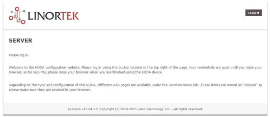
This page is static with no background activity and is a useful place to park if you are not using the SERVER and do not want to close the connection.
By pressing LOGIN, you will be asked for your username and password. These credentials will be retained by the browser until the browser is closed. You can disable the password requirement in Settings page. See section page 21.
Ana Sayfa
Giriş bilgileriniz girildikten sonra uygulamanın ana sayfasına yönlendirileceksiniz. Ana Sayfa veya Dizin sayfası sistem bilgilerinin bir kısmını görüntüler ve fiziksel aygıtın başkalarıyla aynı alanda olması durumunda yerini bulma olanağı sunar. Açıklama için aşağıdaki listeye bakın.

- TIME – Displayed along with the day of the week. This time may be set to be in a 12 hour format with AM/PM indicator or 24 hour format.
- TARİH – Geçerli tarih burada görüntülenir.
- VOLT – Cilttage tahtada görüntülenir. SUNUCU başka ekipmanlarla birlikte çalıştırılıyorsa bu yararlı olabilir.tage variance can be noted. Fargo and Koda servers have an input voltage range of 1248vDC.
- TEMPERATURE – Temperature on the board is displayed. This display may be either °C or °F. This temperature will be affected by the heat generated by SERVER itself so it will always be slightly higher than ambient temperature.
- LED'ler – Görüntülenen 3 LED vardır. KIRMIZI LED sistem darbesidir. Sunucu çalıştığı sürece bu, saniyede bir kez yanıp sönmelidir. YEŞİL LED önyükleyici seçenekleri için kullanılır ve genellikle ekranda görünmez. webalan. MAVİ LED tıklanabilir ve buradan açıp kapatabilirsiniz. web sayfa. Bu, cihazın bağlı olduğu ünite üzerinde yanacağından, diğer benzer ünitelerle birlikte kullanılması halinde cihazın fiziksel olarak konumlandırılması açısından kullanışlıdır. web tarayıcı bağlı. Discoverer programı ayrıca MAVİ LED'in açık olup olmadığını da not edecektir. Buna genellikle "Konumlandırma" işlevi denir.
Hizmetler
Hizmetler sekmesi dinamiktir ve sunucunuzun yapılandırmasına bağlı olarak değişecektir. Girişleri, çıkışları, sensörleri ve diğer özel kontrolleri kontrol edebileceğiniz yer burasıdır.
In/Out or Relays Page
Depending on which SERVER you are using, the first page on the SERVICES tab will be either In/Out or Relays.
In/Out has the relay controls and the input controls on one page, while Relays only has the relay controls.
Röle Kontrolü
An In/Out page is displayed below. Some relay control pages have 2, 4 or 8 relays displayed. Each relay has a number, in this case 1 to 4.

The State LED shows whether the relay is on or off indicated by GREEN and RED respectively. This icon is clickable to manually control the corresponding relay. Each relay can have a Name as well as identifiers for the Normally Open, Common and Normally Closed connections.
Aşağıdakileri gösteren dört durum LED'i vardır:
- Email – If an email is to be sent when this relay is switched on/off
- Darbe – Bu Röle bir darbe genişliği ve darbe genişliği çarpanı (süre) ile ayarlanmışsa – daha fazla bilgi için sonraki bölüme bakın
- Sched. – If there is a schedule created in the Tasks page (see page 15) set to automatically trigger this relay.
- Zamanlı – Darbe ayarlandıysa ve bu röle etkinleştirildiyse, Zamanlı LED kırmızıya dönerek rölenin o anda bir zamanlayıcıda çalıştığını gösterir.
Click the Edit Icon to edit the controls for the corresponding relay. This will take you to the Set Relay page (see page 11).
Girişler
The In/Out or Inputs page (depending on your SERVER) will display information from each input. The SERVERs have a combination of inputs. The Fargo R4DI has four digital inputs, The R4ADI has, four digital inputs, four analog inputs. The KODA SERVER has two digital inputs.
At the top of each input is a label (ex: DIN 1, AIN 2) specifying whether it is a digital input (DIN) or analog input (AIN) as well as the input number. This label will turn green when the input is enabled. Inside the box will be any display configured from the Set Input page (see page 12 for digital input, page 14 for analog input). A red dot in the lower-left corner indicating the state of a linked relay (if any), will turn green when the linked relay is activated.
Finally, an Edit icon in the lower-right corner of the box to edit the corresponding input. This will take you to the Set Digital Input or Set Analog Input page (page 12 or page 14).
Set Relay Page
RÖLEYİ AYARLA sayfası, Röleye ilişkin çeşitli özellikleri ayarlamanıza olanak tanır.
- Relay Select – The Relay that you are editing (identified by the line on which you clicked the Edit icon on the RELAY page).
- Name – Enter a 15-character Relay Name. This and the following 3 fields may be used for any identifying information desired.
- NO Name – Enter a 7-character name for the Normally Open (NO) connection.
- Com Name – Enter a 7-character name for the Common (COM) connection.
- NC Name – Enter a 7-character name for the Normally Closed (NC) connection.
- Pulse Width – When you control the relay it turns on or off. You may control it for a timed turned on period by entering a Pulse Width when 0 means there is no timed event and a number represents duration of the pulse. The maximum number you can enter here is 4 digits, ie. 1234.
- Darbe Genişliği Çarpanı – Darbe uzunluğunu daha ayrıntılı tanımlamak için bir Darbe Genişliği Çarpanı seçerek darbe genişliğini daha ayrıntılı olarak tanımlayın. Şunları seçebilirsiniz:
• Yok
• mS (Millisecond, 1/1000 second)
• Sec (Seconds)
• Min (Minutes) - Röle Tipi – SUNUCU, SUNUCU üzerindeki rölelere fiziksel olarak veya başka yollarla erişebilir. Şunları seçebilirsiniz:
• Normal – relay physically on the SERVER
• Latched – not currently supported
• Remote – a relay on another SERVER accessed over the network
• Zigbee – a relay at a remote device accessed over an RF system
• Normal and Remote – both relays activated
• Normal and Zigbee – both relays activated - Konum Kimliği – bu, uzak bir konumu tanımlayan bir sayıdır
- Konumdaki Röle – Konumdaki röleyi veya cihazı temsil eden bir sayı
- E-posta Gönder – SUNUCU, röle açık veya kapalı olduğunda bir E-posta gönderecek şekilde programlanabilir.

Dijital Giriş Sayfasını Ayarla
Dijital Girişler, çeşitli ekran türlerinin kullanılmasıyla ilgili çeşitli okumalar sağlayacak şekilde ayarlanabilir. Giriş verilerini görüntülemenin yanı sıra, ekranı adlandırabilir ve onunla bir röleyi ilişkilendirebilirsiniz. Bu röle, açıktan kapalıya geçtikçe Yeşilden KIRMIZIya dönecektir ve kontrol etmek için tıklanabilir. Kalem düzenle simgesine tıklayarak bu girişin ayarlarını düzenleyebilirsiniz:
- Digital Input Selected – The Digital Input that you are editing (identified by the line on which you clicked the Edit icon).
- Ad – Bu giriş için 15 karakterlik bir ad ayarlayabilirsiniz. Bu ad ekranın üst kısmındaki çubuğa yazılır.
- Etiket – Gerçek aktif ekranda görüntülenecek 7 karakterli bir etiket ayarlayın.
- Düzeltici – Bu alanı kullanarak, değer görüntüleme sayfasında gösterilmeden önce bir değeri ekleyebilir, çıkarabilir, çarpabilir veya bölebilirsiniz. Bu, her biri tek bir boşluk karakteriyle ayrılan 2 değerli bir düzelticidir. (yani “+2, -2, *3, /3”)
- USE – Bu girişi aktif olarak ayarlar. Giriş numarası göstergesini yeşile çevirir. Girişin kullanım sırasında türüne bağlı olarak CPU zamanını ve diğer kaynakları tükettiğine dikkat edilmelidir. Tüm girişler aynı anda etkin olabilse de yalnızca kullanmak istediklerinizi açmanız önerilir.
- Tür – Giriş verileri bir dizi sonucu hesaplamak için kullanılabilir. Şunları seçebilirsiniz:
• State – This is useful for knowing if an input is on or off, like a door switch being on or off.
• CounterNR – This is a non-resettable counter.
• CounterR – This is a resettable counter.
• Frequency – Counts the frequency of an input in KHz (kilo hertz or1/1000 seconds). This could be useful in displaying a tachometer where 60Hz = 1 R.P.M.
• Period – in 1/1000 seconds an input in kHz (milliseconds or1/1000 seconds). This would be useful for measuring timed events. - Ekran – Bu seçim, kullanılan ekran tipini değiştirmenizi sağlar. Şunları seçebilirsiniz:
• Dot – A single dot with the value in the middle. This can be used for State. You can make a dumb indicator by changing the color of the Dot based on the value. The label is under the Dot.
• Values – Displays the Corrected Value with the Label in a box directly below it.
• Meter – This Meter has configurable scale based on the Min/Max values and arcs can be colored per the Color ranges. The Label is displayed within the Meter.
• VBar – Also based on the Min/Max values for the scale and the bar changes color based on the values in the Color ranges. - Relay L/T – Enter a Relay number here. If it is a local relay it will show GREEN or RED depending if it is on or off. By clicking on it the relay will turn on and off. The name comes from the relay settings page. This may be useful if you want to turn the subject of a display on and off. Any relay can be used on any input and each may be reused for any other input. Adding an L after the relay number (ex: 2L) will link the state of the input to the state of the relay. This is an easy and immediate way to have an input follow the relay. Adding a T after the relay number will trigger the relay to the state of the input. This is an easy and immediate way to have a relay follow the input.
- Command Z/N/I – This field is used for issuing various commands to the Digital Input controller: Z Zero the resettable counter. N Leave the input as Normal. I Invert the input.
- Value – These are Min/Max values used for the display. This is useful for preventing a Meter from going past its end or setting the value of a VBar. This is the Value after the Corrector. The system cannot display a value past Max, so be sure this is at least set to 1.
- Sarı/Kırmızı/Yeşil – Bir ekranı daha da tanımlamak için kullanılabilecek üç renk vardır. Ekran Değerine bir renk tanımlamak için bu renklerin aralığını ayarlayın. Bu, Düzelticiden sonraki Değerdir. Bir Durum türü kullanıyorsanız KIRMIZI = 0'dan 0'a, YEŞİL = 1'den 1'e ve SARI = 2'den 2'ye atamak isteyebileceğinizi unutmayın. Bir Durum her zaman 1 veya 0 olduğundan bu, belirsiz bilgilerin ve SARI rengin kullanılmasını önleyin. Durum türü için istediğiniz iki rengi seçebilirsiniz.

Set Analog Input Page
Analog Girişler, çeşitli ekran türlerinin kullanılmasıyla ilgili çeşitli okumalar sağlayacak şekilde ayarlanabilir. Giriş verilerini görüntülemenin yanı sıra, ekranı adlandırabilir ve onunla bir röleyi ilişkilendirebilirsiniz. Bu röle, açıktan kapalıya geçtikçe Yeşilden KIRMIZIya dönecektir ve kontrol etmek için tıklanabilir.
- Analog Input Selected – The Analog Input that you are editing (identified by the line on which you clicked the Edit icon).
- Ad – Bu giriş için 15 karakterlik bir ad ayarlayabilirsiniz. Bu ad ekranın üst kısmındaki çubuğa yazılır.
- Etiket – Gerçek aktif ekranda görüntülenecek 7 karakterli bir etiket ayarlayın.
- Düzeltici – Bu alanı kullanarak, değer görüntüleme sayfasında gösterilmeden önce bir değeri ekleyebilir, çıkarabilir, çarpabilir veya bölebilirsiniz. Bu, her biri tek bir boşluk karakteriyle ayrılan 2 değerli bir düzelticidir. (yani “+2, -2, *3, /3”)
- USE – Sets this input to active. Turns the input number indicator to GREEN. It should be noted that when in use the input consumes CPU time and other resources depending on its type. Although all inputs may be active at the same time, it is recommended to turn on only those you want to use.
- Tür – Giriş verileri bir dizi sonucu hesaplamak için kullanılabilir. Şunları seçebilirsiniz:
• Analog 1 – Analog 1 input from a SERVER with an input such as found on a R4ADI.
• Analog 2 – Analog 2 input from a SERVER with an input such as found on a R4ADI.
• AC Current 1 – AC current sensor 1 input from a SERVER with an input such as found on a R4ADI.
• AC Current 2 – AC current sensor 2 input from a SERVER with an input such as found on a R4ADI.
• AC Current 3 – Not used
• Volts – The measurement of the voltage powering the SERVER.
• Current – On “S” models, this is the current consumed by the SERVER.
• Int. Temp – Temperature from the board mounted sensor.
• Ext. Temp – Temperature from the “S” model SERVER.
• R. Humidity – % Relative Humidity from the “S” model SERVER.
• MMA X – The X axis accelerometer data from the “S” model SERVER.
• MMA Y – The Y axis accelerometer data from the “S” model SERVER.
• MMA Z – The Z axis accelerometer data from the “S” model SERVER. - Ekran – Bu seçim, kullanılan ekran tipini değiştirmenizi sağlar. Şunları seçebilirsiniz:
1. Dot – A single dot with the value in the middle. This can be used for State. You can make a dumb indicator by changing the color of the Dot based on the value. The label is under the Dot.
2. Values – Displays the Corrected Value with the Label in a box directly below it.
3. Meter – This Meter has configurable scale based on the Min/Max values and arcs can be colored per the Color ranges. The Label is displayed within the Meter.
4. VBar – Also based on the Min/Max values for the scale and the bar changes color based on the values in the Color ranges. - Relay – Enter a Relay number here. If it is a local relay it will show Green or RED depending if it is on or off.
By clicking on it the relay will turn on and off. The name comes from the relay settings page. This may be useful if you want to turn the subject of a display on and off. Any relay can be used on any input and each may be reused for any other input. - Değer – Bunlar ekran için kullanılan Min/Maks değerlerdir. Bu, Metrenin sonunu geçmesini önlemek veya bir VBar'ın değerini ayarlamak için kullanışlıdır. Bu, Düzelticiden sonraki Değerdir. Sistem Maks'ın üzerindeki bir değeri görüntüleyemez; bu nedenle bunun en azından 1'e ayarlandığından emin olun.
- Sarı/Kırmızı/Yeşil – Bir ekranı daha da tanımlamak için kullanılabilecek üç renk vardır. Ekran Değerine bir renk tanımlamak için bu renklerin aralığını ayarlayın. Bu, Düzelticiden sonraki Değerdir. Bir Durum türü kullanıyorsanız KIRMIZI = 0'dan 0'a, YEŞİL = 1'den 1'e ve SARI = 2'den 2'ye atamak isteyebileceğinizi unutmayın. Bir Durum her zaman 1 veya 0 olduğundan bu, belirsiz bilgilerin ve SARI rengin kullanılmasını önleyin. Durum türü için istediğiniz iki rengi seçebilirsiniz.

Tasks Page
The TASKS page displays the automatic events that can be programmed into the SERVER. You can schedule up to 16 events in the SERVER. These are constructed as IF … THEN statements. In addition, the IF term can have 2 elements (IF a, AND/OR/NOT b … THEN c). This provides a simple to program and powerful way to take advantage of the data acquired by the SERVER. The Tasks page shows you an overview of configured tasks. You can click the dot in the State column to turn a task on or off indicated by a green dot for ON, and a red dot for OFF. To edit or create a task, click the Edit icon to the right of the task line. This will take you to the Set Schedule page detailed in the next section.

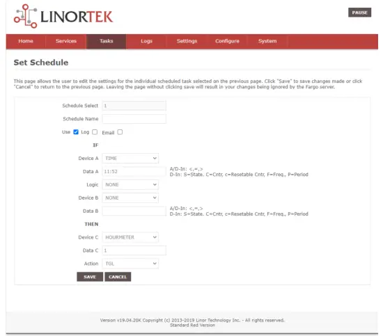
Set Schedule Page
The SET SCHEDULE page allows you to create time and logic-based events that will occur automatically if the conditions are met.
- Schedule Select – Determined by clicking on a schedule line from the previous page.
- Schedule Name – Enter a 15-character Schedule Name.
- USE – In order for a Schedule line to be active you must select the USE button. If there is an error detected in entering Schedule data, the USE box will automatically uncheck.
- GÜNLÜK – Bu öğenin her yürütüldüğünde sistem günlüğünde görünmesi için günlüğü seçin.
- Email – Click Email to automatically send an email when this schedule is executed.
- Device A – Select Device A for the first term in the IF statement from the drop box.
- Data A – Select Data A for the above device. Depending on the device selected, the Data used for testing may have special properties. See the list below for Data that may be entered. If an error is detected indata entry when the “Save” button is pushed, the USE box will uncheck and the Data box containing the error will be highlighted.
• Minute – Enter: mm
• Hour – Enter: hh (use 24-hour system)
• Day – Enter: dd
• DayofWeek – Enter: Sunday = 1, Monday = 2, Tuesday = 3, Wednesday = 4, Thursday = 5, Friday = 6, Saturday = 7, Weekday = 8, Weekend = 9
• Time – Enter: hh:mm (use leading zeros, seconds are ignored) (use 24 hour system) ex:07:30 or 14:05
• Date – Enter: yy/mm/dd (use leading zeros) ex: 20/01/10 for January 10, 2020
• Relay – Enter: Relay number and (+ or -), ex: 01+ for Relay 1 ON or 01- for Relay 1 OFF
• Button – Enter: + or – (for ON or OFF respectively)
• Flag – Enter: Flag number(opt.+), or Flag number (for ON or OFF respectively)
• Temp – Enter: >, = or < value; example: >40 (her zaman C derece)
• Volts – Enter: >, = or < value; example: <10
• Analog – Analog input. Enter an input number and >, = or < and value. Example: 3<123 (This value is raw data value prior to any Corrector used by the input display page.)
• Digital – Digital input. Enter Input Number, Type, >, =, or < and value; example: 1F>7500 (This value is the raw data value prior to any Corrector used on the display page). Type can be (case sensitive):
• S State (On/Off)
• C Non-resettable counter
• c Resettable counter (lower case ‘c’)
• F Frequency in 1/1000 seconds
• P Period in 1/1000 seconds - Mantık – Cihaz A ve Cihaz B arasında bir Mantık karşılaştırması ayarlayın.
• AND – True if: Device A is true AND Device B is true
• OR – True if: Device A is true OR Device B is true
• NOT – True if: Device A is true and Device B is NOT true - Device B – Select Device B for testing from the drop box.
- Veri B – Yukarıdaki cihaz için Veri B'yi seçin. Seçilen cihaza bağlı olarak test için kullanılan Verilerin özel özellikleri olabilir. Yukarıdaki listeye bakın.
- Cihaz C – kontrol edilecek şeydir.
- Veri C – Cihaz C için özelliği ayarla. Söz dizimi şu şekilde kullanılır:
• RELAY – These are relays on this SERVER. You can set up to four per schedule. Enter separated by commas, for examp“1,2,3,4”
• FLAG – This is a storage flag that can be used to make more complex schedules. There are 8 flags that can be turned on or off.
• REMOTE – Refers to a remote SERVER unit. When these conditions are met, this SERVER will send a command to control a remote SERVER. The Data field for a remote unit should be in the format,
“REMOTE UNIT NUMBER, REMOTE UNIT RELAY”. For example, “3,5”. Bu uzak SUNUCULAR, Yapılandır/Uzak Cihaz Yapılandırma sayfasında tanımlanmalıdır.
• COUNTER – Adds count to digital input counter – set as 1 or 2 depending on which digital input is counting
• BLUE LED – No data.
• eMAIL – Will send eMail, no data.
• NOTIFY – Will send notification to Kodalert, set 1- 8 for Settings/Alarm Notification number. (Not Implemented) - Eylem – Cihaz C ile ne yapılmalı. Seçenekler şunlardır:
• ON – Turns device ON
• OFF – Turns device OFF
• TGL – Toggles state of Device C
• RESET – Resets CounterR

Günlükler Sayfası
The Logs tab displays over 10,000 entries from actions taken by the SERVER or by users themselves. This feature allows several actions for the convenience of displaying and collecting data from the SERVER.
- The checkboxes above the date allow the user to filter logs from different sources. To filter out logs you do not wish to see from a certain source simply uncheck the box.
- Each log has a reference number and a time and date attached in a “yyyy/mm/dd” and “hh:mm:ss” format. Afterwards is the event displayed.
- To scroll through the logs, use the arrows to the right-hand side, where the horizonal line and arrow brings you to the start or end, the double arrow moves up or down a page, and the single arrow moves up or down a single log.
- To refresh the logs manually click the REFRESH button below the Log Details.
- To download the Log Details, click the DOWNLOAD button below the Log Details, this allows you to save the logs as a separate file.
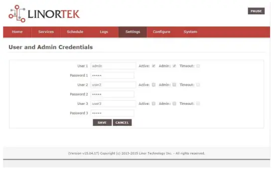
Kullanıcı ve Yönetici Kimlik Bilgileri Sayfası
Use this page from the Settings drop down menu. Here you can set up to 3 users for your SERVER system. As a default only User 1 is Active. Here you can:
- User Name and Password – Each user has their own credentials. As a default these are set toadmin/admin, user2/user2 and user3/user3 for Users 1, 2 and 3 respectively. The passwords are never displayed. Not: when you reset the password, it must be less than 13-character.
- Etkin – Bu kullanıcının oturum açması için işaretlenmelidir, Kullanıcı 1'i devre dışı bırakamazsınız.
- Yönetici – Çoğu sayfada yalnızca yönetici veri kaydedebilir. Bu, SUNUCUSUNUZU yetkisiz kişiler tarafından değiştirilmeye karşı korur.
- Zaman Aşımı – Şu anda etkin değil.
Saat/Tarih Sayfası
Bu sayfayı Ayarlar açılır menüsünden kullanın. Bu sayfa saat ve tarih sistemini ayarlamanızı sağlar.
- Time – Set time using an hh:mm:ss format.
- Tarih – Tarihi yy/aa/gg formatını kullanarak ayarlayın.
- Time Zone – Set desired time zone 5 for EST, 8 for PST, you can now add a :mm for setting part hour, for example, 5:30, 5 saat 30 dakikalık bir zaman dilimidir.
- Yaz Saati Uygulamasını Kullan – Yaz saati uygulaması gününde sistem saatinizi otomatik olarak ayarlamak için seçin. (Tüm zaman dilimlerinde doğru değildir.)
- MIL Saatini Kullan – 24 saatlik formatı kullanmak için seçin.
- Use NTP Update – Select to synchronize SERVER time with NTP server
- NTP Web Site – Bu, güncellemeler için seçilen NTP sunucusudur.
- NTP Aralığı – Güncellemeler arasındaki dakika cinsinden zaman aralığı.
- Log NTP Event – Normally NTP exceptions will be logged, select this option to Log every NTP event. (May be useful in debugging.)

Ayarlar Sayfası
Access this page from the Settings dropdown menu. Select these settings to enable various features in the SERVER
- Use Active Main – No longer used. (Select PAUSE to go inactive.)
- Oturum Açmayı Gerektir – Seçilmezse SUNUCU, kimlik bilgileri olmadan tüm erişime izin verecektir.
- Use IP Ranges – Not Implemented.
- Use RESTFUL IP Ranges – Not implemented.
- Use Remote IP Ranges – Not implemented.
- RESTful Kimlik Doğrulamasını Kullan – RESTful için kullanıcı adı ve parolayı zorunlu kılın.
- Röle Aralığını Genişlet – 8 röleyi etkinleştirir.
- Röle Radyo Düğmelerini Kullan – Ayarlanırsa, bir röle açıldığında diğerleri kapatılır.
- SSL Port No. – Not supported – For future use.
- Sistem e-postalarını kullan – Ek e-posta mesajlarını etkinleştirir.
- Fahrenheit Kullan – Santigrat veya Fahrenhayt'ı seçer.
- PGM Dynamic Relays – Changes properties of relays in task schedule.
- CLR PGMs on Start – Reinitialize tasks on start up.
- RTC Temperature Compensation – All Koda boards can add Temperature and Humidity sensor.
- AM2302 kullanın – AM2302 Sıcaklık ve Nem sensörünü kullanın (ayrıca satılır).
- Java Report – Send data to HourCollector app over ethernet (only for IoTMeter)
- Use Metric – Not supported – For future use.
- UART Usage – Enter “Audio” for Netbell-NTG, “Clock” for Netbell clock.
- Switch Bypass (1/2) – Ignores physical inputs if set. For example, in a Koda 200 board, you want to ignore input 1 switch, check Switch Bypass 1
- Setting 19 – Not supported – For future use
- Sesi Kullan File System – Activate SD Card reader for Netbell-NTG
- WiFi Report – Enable data transfer over WiFi (WiFi IoTMeter only)
- Active Landing Page – Not supported – For future use.
- . Invert Relay Control – The relay is set to NO by default. By checking this box the relay will be inverted to NC.
- Setting 24 – Not supported – For future use.

Dinamik DNS Sayfası
Access this page from the Configure dropdown menu. From this page you can assign dynamic DNS settings. This page, along with proper port forwarding through the router, can enable global access to a device behind a NAT router or firewall. You will need to assign a static IP address and port number (see Network Config Page on page 25) and port the IP address on your router (refer to your router’s user manual). An internet IP address will have to be hosted in order to access your SERVER from the internet. Currently the only IP hosting service supported is provided by DynDNS (https://dyn.com)
- DDNS Kullan – Bu hizmeti etkinleştirir.
- DDNS Hizmeti – Açılır kutudan bir hizmet seçin. Şu anda desteklenen tek hizmet DynDNS'dir
- Kullanıcı Adı – Bu, DDNS Hizmetinde kurulan hesabı ifade eder.
- Şifre – DDNS servisine erişim için şifre.
- Host – This is the IP name registered at the DDNS service for rerouting to this SERVER

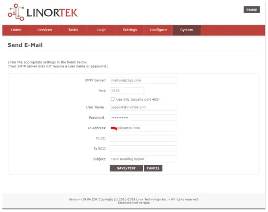
E-posta Kurulum Sayfası
SUNUCUnun çeşitli modüllerden e-posta mesajları gönderirken kullanması için bir e-posta hesabı oluşturun. Bu sayfaya Yapılandır sekmesinden erişin.
Not: This unit is NOT compatible with SSL/TLS, there are 3rd party SMTP delivery servers which do not require SSL and can be used. For instructions on how to use a 3rd party SMTP delivery service, please refer to Appendix 1 at the end of this manual).
- SMTP Sunucusu – Kullanmak istediğiniz giden posta sunucusunu girin.
- Bağlantı Noktası – Bu, söz konusu sunucudaki bağlantı noktasıdır. Bu bilgilerin yanı sıra diğer kurulum alanları için posta hizmetinizi çevrimiçi olarak arayabilirsiniz.
- SSL Kullan – 3. taraf SMTP sunucusunu kullanırken işaretlemeden bırakın.
- Kullanıcı Adı – E-posta hesap adınız.
- Şifre – E-posta hesabı şifresi.
- To Address – Enter up to 3 address for this email set up. An addressee, a CC and a BC.
- Konu – E-posta başlığının konu satırı.

Ağ Yapılandırma Sayfası
Access this page from the Configure dropdown menu. This page allows the configuration of the SERVER’s network settings.
DİKKAT: Incorrect settings may cause the board to lose network connectivity. In order to access a device in your network remotely you must PORT the device. This tells your router that information coming in should be sent to a specific device on your network.
- MAC Address – This is a unique MAC address that is assigned to this product at time of assembly. It cannot be altered.
- Ana Bilgisayar Adı – Bu, bu ünitenin bazı ağlarda adreslenebileceği bir Netbios adıdır. Ayrıca yönlendiricinizin kiralama dizininde de görünebilir. SERVER'ınızı adlandırmak için kullanışlı bir yer oluşturur ve Ana Sayfa'da ve Discoverer'da görünür.
- Port Numarası – Bu, IP adresinin bir parçası haline gelir ve İnternet erişimi için gereklidir. Bu ayarlanmazsa, SERVER varsayılan olarak 80 port numarasına ayarlanır.
- IP Address – Typically you only change the last group of numbers. If you change this IP address make sure to reserve this IP on your router and no other devices are using this IP address or you may not be able to reach this SERVER. If this happens you may need to Restore Defaults using the push button method.
- Ağ Geçidi – Genellikle TCP/IP ağınızdaki, İSS'nize erişim noktası görevi gören bir yönlendiricidir.
- Alt Ağ Maskesi – Bir IP adresini maskeleyen ve IP adresini ağ adresi ve ana bilgisayar adresi olarak bölen 32 bitlik bir sayı. Bunu 255.255.255.0 olarak bırakın
- Birincil DNS – Birincil DNS.
- İkincil DNS – İkincil DNS.

IP Aralığı Yapılandırma Sayfası
Access this page from the Configure dropdown menu. Use these security settings to select a range of IP address that will be allowed to access the SERVER.CAUTION: Incorrect settings may cause the board to lose network connectivity. Not implemented on this SERVER.
Uzak Cihazlar Sayfası
Access this page from the Configure dropdown menu. These settings allow the SERVER to remotely control the relays on another SERVER. This is done by selecting the Remote Device in the Schedule program or by setting up a relay as a REMOTE. There are 8 possible REMOTE locations.
DİKKAT: Yanlış ayarlar kartın uzak bağlantılarını kaybetmesine neden olur.
- Cihaz Adı – İleride başvurmak üzere bu cihaz için bir metin adı girin.
- IP Adresi – Bağlantı noktası numarası da dahil olmak üzere uzak aygıtın IP adresi.
- Kullanıcı Adı – Temel Kimlik Doğrulamada kullanılır.
- Password – Used in Basic Authentication.

Kodalert Page
Not Yet Implemented. Access this page from the Configure dropdown menu. Kodalert provides an interface for alerts of Internet connected devices. Kodalert is a cloud based, open platform monitoring and alert system for the Internet of Things in your physical world. Any Thing that can send an email or TCP messages including our SERVERS, other manufactures devices and people using email can use Kodalert. It can work for multiple remote locations, alert multiple users instantly using the rules you setup by text, email, smart phone Apps push notification or audible alarm instantly when something happens.
- Uyarı Numarası
- Test
- Kullanmak
- Kural
In the Alarm Notification page, you can change the state (on/off) of the relay by clicking the green circle in the state column. Push the EDIT icon to change the Alarm’s settings.

Özellikler
FARGO R8G2
- 10M/100M RJ45 Internet interface with connection and activity LEDs
- 8 Relay outputs, 1FORMC 48 Volt Max (24VAC/DC 3A)
- Status LEDs (pulse, bootloader, and locate)
- Ethernet Bootloader (for server hardware code upgrade)
- PoE or 12VDC @500mA (nominal)
- Web interface w/basic authentication
- On board temperature sensor and voltage sensörü
Reset /Locate pushbutton (blue LED) - Working Temperature from 0 to +70 Celsius
- Storage Temperature from 40 to +125 Celsius
- Humidity from 10% to 80% noncondensing
- Dimensions 74mm x 100mm x 20mm, mounting holes 64mm x 92mm Ф 3.2mm 4 places
- Desteklenen Protokoller: HTTP/SMTP/SNTP
FARGO R4G2
- 10M/100M RJ45 Internet interface with connection and activity LEDs
- 4 1FormC relays 48 Volt Max (24VAC/DC 3A)
- 2 optically isolated digital inputs, 12V 1mA or pulldown switch selectable, 2 conductor screw terminal connectors for each.
- 2 Analog 0-5VDC Inputs 30mA 3.3VDC power source PTC protected. 3 conductor screw terminal connectors for each (3.3VDC, input, ground) (R4ADI only)
- 2 Current sensor inputs. 3.5mm stereo jack connector for each (R4ADI only)
- Status LEDs (pulse, bootloader, and locate)
- Ethernet Bootloader (for server hardware code upgrade
- POE or 12VDC @500mA (nominal)
- Web interface w/basic authentication
- On board temperature sensor and voltage sensörü
- Reset/Locate pushbutton
- Working Temperature from 0 to +70 Celsius
- Storage Temperature from 40 to +125 Celsius
- Humidity from 10% to 80% noncondensing
- Dimensions 74mm x 100mm x 20mm, mounting holes 64mm x 92mm Ф 3.2mm 4 places
- Desteklenen Protokoller: HTTP/SMTP/SNTP
KODA100
- 10M/100M RJ45 Internet interface with connection and activity LEDs
- 2 1-Form-A relay 48VAC@8A Max
- 2 optically isolated digital inputs, 12V 1mA or pulldown switch selectable
- Status LEDs (pulse, bootloader, and locate)
- Ethernet Bootloader (for server hardware code upgrade)
- POE or 12VDC @500mA (nominal)
- Web interface w/basic authentication
- On board temperature sensor and voltage sensörü
- Reset/Locate pushbutton (blue LED)
- Working temperature from 0 to +70 Celsius
- Storage temperature from 40 to +125 Celsius
- Humidity from 10% to 80% noncondensing
- Boyutlar: 70mm x 100mm x 25mm
- Desteklenen Protokoller: HTTP/SMTP/SNTP
KOD200
- 10M/100M RJ45 Internet interface with connection and activity LEDs
- 4 1FormA relays 48 Volt Max 1A dry contact or drive 10V ±10% 50mA to external devices
- 2 optically isolated digital inputs, 12V 1mA or pulldown switch selectable
- Status LEDs (pulse, bootloader, and locate)
- Ethernet Bootloader (for server hardware code upgrade)
- POE or 12VDC @500mA (nominal)
- Web interface w/basic authentication
- On board temperature sensor and voltage sensörü
- Reset/Locate pushbutton (blue LED)
- Working Temperature from 0 to +70 Celsius
- Storage Temperature from 40 to +125 Celsius
- Humidity from 10% to 80% noncondensing
- Boyutlar: 70mm x 100mm x 25mm
- Desteklenen Protokoller: HTTP/SMTP/SNTP
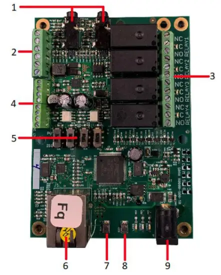
Kart Referans Düzeni
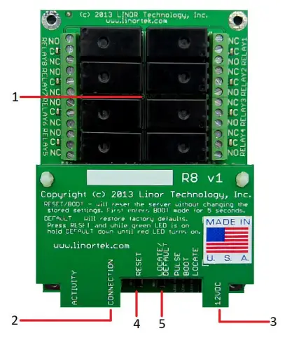
Fargo R8
- 8 Relay outputs, 1FORMC 48 Volt Max (24VAC/DC 3A)
- Rj45 Bağlayıcı
- Güç Konektörü (12VDC)
- Sıfırlama Düğmesi
- Bul Düğmesi
Fargo R4
- 3.5mm Inputs for AC Current Sensor (R4ADI Only)
- Analog Inputs (R4ADI Only)
- 4 Relay outputs, 1FORMC 48 Volt Max (24VAC/DC 3A)
- Dijital Girişler
- Digital Input Switches (Input 1 on right.
Up: Pullup, Down: Isolated) - Rj45 Bağlayıcı
- Sıfırlama Düğmesi
- Bul Düğmesi
- Güç Konektörü (12VDC)
koda 100
- Digital Inputs (#1 on the left) 5VDC-48VDC (12VDC-48VDC must use the external resistor)
- Relay Outputs (#1 is on the right) 8A@48VAC Max
- Digital Input Switches (IN 1 on left. UP: Isolated, Down: Pullup)
- Sıfırlama Düğmesi
- Yeniden Yükle Düğmesi (mavi LED'i açar – Discoverer'da tanımlar)
- Rj45 Bağlayıcı
- Güç Konektörü (12VDC)
- Sıcaklık/Nem Sensörü için USB Mini Konektör (ayrı satılır)

koda 200
- Digital Inputs (#1 on the left) 5VDC-48VDC (12VDC-48VDC must use the external resistor)
- Relay Outputs (#1 is on left) 48 Volt Max 1A dry contact or drive 10V ±10% 50mA
- Digital Input Switches (IN 1 on left. UP: Isolated, Down: Pullup)
- Relay Switches (Up for dry contact, down for 10V/50mA)
- Sıfırlama Düğmesi
- Yeniden Yükle Düğmesi (mavi LED'i açar – Discoverer'da tanımlar)
- Rj45 Bağlayıcı
- Güç Konektörü (12VDC)
- Sıcaklık/Nem Sensörü için USB Mini Konektör (ayrı satılır)

Fabrika Ayarlarına Sıfırlama
To perform a factory Reset, push the Reset button. When the green LED turns on, push and hold the Reload button until the flashing red LED turns off and then turns on solid. Refer to Board Reference Layout section for the button locations on your device.
This user-manual supplements the documentation for the following Linortek products:
- Netbell-2
- Netbell-8
- Netbell-K (and variants)
- iTrixx-NHM
For more information, documentation and how-to videos, visit https://www.linortek.com/downloads/
Bu belge şu adreste bulunabilir: www.linortek.com/downloads/documentations/
Cihazınızla ilgili yardıma ihtiyacınız varsa lütfen adresini ziyaret edin. www.linortek.com/technical-support
Linor Teknoloji A.Ş.
Bilgiler önceden haber verilmeksizin değiştirilebilir.
Ek 1
Linortek Fargo ve Koda Cihazları için 3. Taraf SMTP Hizmeti Kullanarak SSL E-postaları Nasıl Gönderilir
Varsayılan olarak Koda/Fargo cihazları, SSL olmayan SMTP e-posta sunucularını kullanır. Ancak günümüzde e-posta sunucularının çoğu SSL güvenlik protokolüne geçmiştir, SSL gerektirmeyen ve kullanılabilen 3. parti SMTP dağıtım sunucuları vardır. Piyasada çok sayıda SMTP e-posta servis sağlayıcısı bulunmaktadır. SMTP2GO'yu eski olarak kullanıyoruzampKurulum sürecini göstermek için. SMTP2GO'nun ayda 1000 e-postaya kadar kullanımı ücretsizdir. SMTP2GO'yu kullanmak için lütfen şu adresi ziyaret edin: https://www.smtp2go.com/ .
Adım 1. SMTP2GO hesabını oluşturun.
Bir hesap oluşturmak için “Kaydol”a tıklayın, ölçekte “1K E-posta”yı seçin ve “Ücretsiz plan”ı seçin (Ayda 1000'den fazla e-posta göndermeniz gerekiyorsa, gereksinimlerinizi karşılayan planı seçin.)

SMTP2GO'da bir hesap oluşturmak için kurumsal bir e-posta adresine ihtiyaç duyulacaktır. Gmail veya Yahoo gibi ücretsiz e-posta hizmeti devam etmenize izin vermez. SMTP2GO hesabınızı etkinleştirdikten sonra bir kullanıcı eklemeniz gerekir.
Adım 2. Bir kullanıcı ekleyin.
SMTP2GO'da oluşturduğunuz kullanıcı, e-posta raporları göndermek için Fargo/Koda cihazını kurduğunuzda Giden posta sunucusu olacaktır, lütfen Yahoo veya Gmail gibi ücretsiz e-posta hesaplarını kullanıyorsanız şirket e-posta sunucunuzun e-postaları engellemeyeceğinden emin olun. buraya bir kullanıcı ekleyin.
SMTP2GO hesabınıza giriş yapın, sol taraftaki menüden “Ayarlar” > “SMTP Kullanıcıları”nı seçin, “SMTP kullanıcısı ekle”ye tıklayın ve formu doldurun.
 Kullanıcı SMTP2GO hesabınıza eklendikten sonra, Fargo/Koda cihazlarınızda e-posta bildirimini ayarlamak için ihtiyacınız olan bilgileri gösterecektir.

Adım 3. Linortek cihazını yapılandırın.
Bir hesap oluşturup bir kullanıcı ekledikten sonra, Linortek cihazınızda oturum açın, E-posta bildirimini ayarlamak için Yapılandır – E-posta kurulumu sayfasına gidin:
- SMTP Sunucusu – Kullanmak istediğiniz giden posta sunucusunu girin, eski adresimizde mail.smtp2go.comampley.
- Bağlantı Noktası – Bu, o sunucudaki bağlantı noktasıdır. SMTP bağlantı noktası, eski sistemimizde 2525'tir.ampley.
- SSL Kullan – 3. taraf SMTP sunucusunu kullanırken işaretlemeden bırakın.
- Kullanıcı Adı – Önceki adımda bir kullanıcı oluşturduğumuzda SMTP2GO'dan gelen kullanıcı adı.
- Şifre – Önceki adımda bir kullanıcı oluşturduğumuzda SMTP2GO'dan kullanıcının şifresi.
- Adrese – Bu e-posta kurulumu için en fazla 3 adres girin. Bir muhatap, bir CC ve bir BC.
- Konu – E-posta başlığının konu satırı.
“Kaydet/Test Et” düğmesine basar basmaz cihaz otomatik olarak test e-postasını gönderir. Lütfen Gelen Kutusu klasöründe değilse, onu bulmak için Önemsiz/Diğer klasörünü kontrol edin.
Adım 4. Otomatik E-posta bildirimleri için görevi ayarlayın.
You should be able to receive email notifications for various events from the Fargo/Koda boards at this point. If you need to receive condition logic notification, you can use our condition logic configuration to setup such report. To setup the logic condition report notification, go to Tasks page on your Fargo/Koda device, click the Edit icon of a Schedule. For details of how to create a logic-based event, please refer to the Set Schedule Page on the Fargo/Koda User Manual, which can be downloaded here:
https://www.linortek.com/download/fargo%20g2_koda%20downloads/fargo%20g2_koda%20documentation/Fargo-G2-and-Koda-User-Manual.pdf
Bu s'deample Network Hour Meter cihazını eski olarak kullanacağızampHer gün saat 11:52'de e-posta raporlarının nasıl alınacağı hakkında le.
Görevin tüm koşulları karşılanır karşılanmaz aşağıdaki e-postayı alırsınız:
Hour Reading Report
![]() destek@linortek.com
destek@linortek.com
Mon 4/11/2022 11:52 AM
To: Liyu Nalven
HM 1, my machine, is at 000242.01 hrs.
Reply Forward
![]()
Belgeler / Kaynaklar
 |
LINORTEK Fargo G2 TCP/IP Web Tabanlı Röle Kontrolörü [pdf] Kullanıcı Kılavuzu Fargo G2, Koda, Fargo G2 TCP-IP Web Based Relay Controller, Web Based Relay Controller, Based Relay Controller, Relay Controller |