Danfoss MCD 202 EtherNet-IP Module

Informacioni i produktit
Specifikimet
The EtherNet/IP Module is designed for use with 24 V AC/V DC and 110/240 V AC control voltage. It is not suitable for use with the MCD 201/MCD 202 compact starters using 380/440 V AC control voltage. The module allows a Danfoss soft starter to connect to an Ethernet network for control and monitoring.
Hyrje
Qëllimi i Manualit
This installation guide provides information for the installation of the EtherNet/IP option module for VLT® Compact Starter MCD 201/MCD 202 and VLT® Soft Starter MCD 500. The installation guide is intended for use by qualified personnel.
Users are assumed to be familiar with:
- VLT® soft starters.
- EtherNet/IP technology.
- PC or PLC that is used as a master in the system.
Lexoni udhëzimet përpara instalimit dhe sigurohuni që të respektohen udhëzimet për instalim të sigurt.
- VLT® është një markë e regjistruar tregtare.
- EtherNet/IP™ është një markë tregtare e ODVA, Inc.
Burime Shtesë
Resources available for the soft starter and optional equipment:
- The VLT® Compact Starter MCD 200 Operating Instructions provide the necessary information for getting the soft starter up and running.
- The VLT® Soft Starter MCD 500 Operating Guide provides the necessary information for getting the soft starter up and running.
Publikimet dhe manualet plotësuese janë në dispozicion nga Danfoss. Shiko drives.danfoss.com/knowledge-center/technical-documentation/ për listat.
Produkti Mbiview
Përdorimi i synuar
This installation guide relates to EtherNet/IP Module for VLT® soft starters.
The EtherNet/IP interface is designed to communicate with any system complying with the CIP EtherNet/IP standard. EtherNet/IP provides users with the network tools to deploy standard Ethernet technology for manufacturing applications while enabling internet and enterprise connectivity.
EtherNet/IP Module is intended for use with:
- VLT® Compact Starter MCD 201/MCD 202, 24 V AC/V DC and 110/240 V AC control voltage.
- VLT® Soft Starter MCD 500, all models.
NJOFTIM
- The EtherNet/IP Module is NOT suitable for use with the MCD 201/MCD 202 compact starters using 380/440 V AC control voltage.
- The EtherNet/IP Module allows a Danfoss soft starter to connect to an Ethernet network and be controlled or monitored using an Ethernet communication model.
- Separate modules are available for PROFINET, Modbus TCP, and EtherNet/IP networks.
- The EtherNet/IP Module operates at the application layer. Lower levels are transparent to the user.
- Familiarity with Ethernet protocols and networks is required to operate the EtherNet/IP Module successfully. If there are difficulties when using this device with third-party products, including PLCs, scanners, and commissioning tools, contact the relevant supplier.
Miratimet dhe vërtetimet

Ka më shumë miratime dhe çertifikime. Për më shumë informacion, kontaktoni një partner lokal të Danfoss.
Asgjesimi
Mos i hidhni pajisjet që përmbajnë komponentë elektrikë së bashku me mbeturinat shtëpiake.
Mblidhni atë veçmas në përputhje me legjislacionin vendas dhe aktual.
Simbolet, shkurtesat dhe konventat
| Shkurtesa | Përkufizimi |
| CIP™ | Protokolli i përbashkët industrial |
| DHCP | Protokolli i konfigurimit dinamik të hostit |
| EMC | Pajtueshmëria elektromagnetike |
| IP | Protokolli i internetit |
| LPK | Paneli i kontrollit lokal |
| LED | Diodë që lëshon dritë |
| PC | Kompjuter personal |
| PLC | Kontrollues logjik i programueshëm |
Tabela 1.1 Simbolet dhe shkurtesat
Konventat
Listat e numëruara tregojnë procedurat.
Listat e pikave tregojnë informacione të tjera dhe përshkrime të ilustrimeve.
Teksti i pjerrët tregon:
- Referenca e kryqëzuar.
- Lidhje.
- Emri i parametrit.
- Emri i grupit të parametrave.
- Opsioni i parametrave.
Siguria
Në këtë manual përdoren simbolet e mëposhtme:
PARALAJMËRIM
Tregon një situatë potencialisht të rrezikshme që mund të rezultojë në vdekje ose lëndim serioz.
KUJDES
Tregon një situatë potencialisht të rrezikshme që mund të rezultojë në lëndime të lehta ose të moderuara. Mund të përdoret gjithashtu për të paralajmëruar kundër praktikave të pasigurta.
NJOFTIM
Tregon informacione të rëndësishme, duke përfshirë situatat që mund të rezultojnë në dëmtim të pajisjeve ose pronës.
Personel i kualifikuar
Correct and reliable transport, storage, installation, operation, and maintenance are required for the trouble-free and safe operation of the soft starter. Only qualified personnel are allowed to install or operate this equipment.
Qualified personnel are defined as trained staff, who are authorized to install, commission, and maintain equipment, systems, and circuits in accordance with pertinent laws and regulations. Also, the qualified personnel must be familiar with the instructions and safety measures described in this installation guide.
Paralajmërime të Përgjithshme
PARALAJMËRIM
RREZIK NGA GODITJA ELEKTRIKE
VLT® Soft Starter MCD 500 contains dangerous voltages kur lidhet me rrjetin voltage. Only a qualified electrician should carry out the electrical installation. Improper installation of the motor or the soft starter can cause death, serious injury, or equipment failure. Follow the guidelines in this manual and local electrical safety codes.
Models MCD5-0360C ~ MCD5-1600C:
Treat the busbar and heat sink as live parts whenever the unit has mains voltage connected (including when the soft starter is tripped or waiting for a command).
PARALAJMËRIM
Tokëzimi i duhur
- Shkëputni motorin e butë nga rrjeti voltage before carrying out repair work.
- It is the responsibility of the person installing the soft starter to provide proper grounding and branch circuit protection according to local electrical safety codes.
- Do not connect power factor correction capacitors to the output of the VLT® Soft Starter MCD 500. If static power factor correction is employed, it must be connected to the supply side of the soft starter.
PARALAJMËRIM
IMMEDIATE START
In auto-on mode, the motor can be controlled remotely (via remote inputs) while the soft starter is connected to mains.
MCD5-0021B ~ MCD5-961B:
Transportation, mechanical shock, or rough handling may cause the bypass contactor to latch into the On state.
To prevent the motor from starting immediately on first commissioning or operation after transportation:
- Always ensure that the control supply is applied before the power.
- Applying control supply before power ensures that the contactor state is initialized.
PARALAJMËRIM
FILLIM I PAQËLLIMSHËM
When the soft starter is connected to AC mains, DC supply, or load sharing, the motor can start at any time. Unintended start during programming, service, or repair work can result in death, serious injury, or property damage. The motor can start with an external switch, a fieldbus command, an input reference signal from the LCP or LOP, via remote operation using MCT 10 Set-up Software, or after a cleared fault condition.
Për të parandaluar ndezjen e paqëllimshme të motorit:
- Shtypni [Off/Reset] në LCP përpara se të programoni parametrat.
- Disconnect the soft starter from the mains.
- Completely wire and assemble the soft starter, motor, and any driven equipment before connecting the soft starter to AC mains, DC supply, or load sharing.
PARALAJMËRIM
SAFETY OF PERSONNEL
The soft starter is not a safety device and does not provide electrical isolation or disconnection from the supply.
- If isolation is required, the soft starter must be installed with a main contactor.
- Do not rely on the start and stop functions for safety of personnel. Faults occurring in the mains supply, the motor connection, or the electronics of the soft starter can cause unintended motor starts or stops.
- If faults occur in the electronics of the soft starter, a stopped motor may start. A temporary fault in the supply mains or loss of motor connection can also cause a stopped motor to start.
To provide safety of personnel and equipment, control the isolation device through an external safety system.
NJOFTIM
Before changing any parameter settings, save the current parameter to a file using MCD PC Software or the Save User Set function.
NJOFTIM
Use the Autostart feature with caution. Read all the notes related to Autostart before operation.
Ishamptë dhënat dhe diagramet në këtë manual janë përfshirë vetëm për qëllime ilustruese. Informacioni i përfshirë në këtë manual mund të ndryshojë në çdo kohë dhe pa njoftim paraprak. Përgjegjësia ose përgjegjësia nuk pranohet kurrë për dëme të drejtpërdrejta, të tërthorta ose konsekuente që vijnë nga përdorimi ose aplikimi i kësaj pajisjeje.
Instalimi
Procedura e instalimit
KUJDES
DËMTIMET E PAJISJEVE
If mains and control voltage are applied when installing or removing options/accessories, it may damage the equipment.
Për të shmangur dëmtimin:
Hiq rrjetin dhe kontrollin voltage from the soft starter before attaching or removing options/accessories.
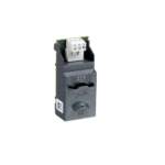
Installing the EtherNet/IP option:
- Hiqni fuqinë e kontrollit dhe furnizimin me energji elektrike nga motori i butë.
- Fully pull out the top and bottom retaining clips on the module (A).
- Line up the module with the communication port slot (B).
- Push in the top and bottom retaining clips to secure the module to the soft starter (C).
- Connect Ethernet port 1 or port 2 on the module to the network.
- Aplikoni fuqinë e kontrollit në motorin e butë.

Remove the module from the soft starter:
- Hiqni fuqinë e kontrollit dhe furnizimin me energji elektrike nga motori i butë.
- Disconnect all external wiring from the module.
- Fully pull out the top and bottom retaining clips on the module (A).
- Tërhiqeni modulin nga motori i butë.

Lidhja
Soft Starter Connection
The EtherNet/IP Module is powered from the soft starter.
VLT® Compact Starter MCD 201/MCD 202
For the EtherNet/IP Module to accept fieldbus commands, fit a link across terminals A1–N2 on the soft starter.
VLT® Soft Starter MCD 500
If the MCD 500 has to be operated in remote mode, input links are required across terminals 17 and 25 to terminal 18. In hand-on mode, links are not required.
NJOFTIM
FOR MCD 500 ONLY
Control via the fieldbus communication network is always enabled in local control mode and can be enabled or disabled in remote control mode (parameter 3-2 Comms in Remote). See the VLT® Soft Starter MCD 500 Operating Guide for parameter details.
EtherNet/IP Module Connections
| MCD 201/202 | MCD 500 | ||||
 |
 |
||||
| 17 | |||||
| A1 | 18 | ||||
| N2 | |||||
| 25 | |||||
| 2 | 2 | ||||
| 3 | 3 | ||||
| 1 | A1, N2: Stop input | 1 | (Auto-on mode) 17, 18: Stop input25, 18: Reset input | ||
| 2 | EtherNet/IP Module | 2 | EtherNet/IP Module | ||
| 3 | Portet Ethernet RJ45 | 3 | Portet Ethernet RJ45 | ||
Table 4.1 Connection Diagrams
Lidhja në rrjet
Portet Ethernet
The EtherNet/IP Module has 2 Ethernet ports. If only 1 connection is required, either port can be used.
Kabllot
Suitable cables for EtherNet/IP Module connection:
- Kategoria 5
- Kategoria 5e
- Kategoria 6
- Kategoria 6e
Masat paraprake të EMC
To minimize electromagnetic interference, Ethernet cables should be separated from motor and mains cables by 200 mm (7.9 in).
The Ethernet cable must cross the motor and mains cables at an angle of 90°.
| 1 | Furnizimi 3fazor |
| 2 | kabllo Ethernet |
Illustration 4.1 Correct Running of Ethernet Cables
Krijimi i Rrjetit
The controller must establish communication directly with each device before the device can participate in the network.
Duke iu drejtuar
Each device in a network is addressed using a MAC address and an IP address and can be assigned a symbolic name associated with the MAC address.
- The module receives a dynamic IP address when it is connected to the network or can be assigned a static IP address during configuration.
- The symbolic name is optional and must be configured within the device.
- The MAC address is fixed within the device and is printed on a label on the front of the module.

Konfigurimi i pajisjes
Në bord Web Serveri
Ethernet attributes can be configured directly in the EtherNet/IP Module using the on-board web server.
NJOFTIM
The Error LED flashes whenever the module receives power but is not connected to a network. The Error LED flashes throughout the configuration process.
NJOFTIM
The default address for a new EtherNet/IP Module is 192.168.0.2. The default subnet mask is 255.255.255.0. The web server only accepts connections from within the same subnet domain. Use the Ethernet Device Configuration Tool to temporarily change the network address of the module to match the network address of the PC running the tool, if required.
To configure the device using the on-board web server:
- Attach the module to a soft starter.
- Connect Ethernet port 1 or port 2 on the module to the network.
- Aplikoni fuqinë e kontrollit në motorin e butë.
- Start a browser on the PC and enter the device address, followed by /ipconfig. The default address for a new EtherNet/IP Module is 192.168.0.2.

- Edit the settings as required.
- Click Submit to save the new settings.
- To store the settings permanently in the module, tick Set permanently.
- If prompted, enter username and password.
- Username: Danfoss
- Password: Danfoss
NJOFTIM
If an IP address is changed and its record is lost, use the Ethernet Device Configuration Tool to scan the network and identify the module.
NJOFTIM
If changing the subnet mask, the server is unable to communicate with the module after the new settings are saved.
Ethernet Device Configuration Tool
Download the Ethernet Device Configuration Tool from www.danfoss.com/drives.
Changes made via the Ethernet Device Configuration Tool cannot be stored permanently in the EtherNet/IP Module. To configure attributes permanently in the EtherNet/IP Module, use the on-board web server.
Configuring the device using the Ethernet Device Configuration Tool:
- Attach the module to a soft starter.
- Connect Ethernet port 1 or port 2 on the module to the Ethernet port of the PC.
- Aplikoni fuqinë e kontrollit në motorin e butë.
- Hapni Mjetin e Konfigurimit të Pajisjes Ethernet.

- Klikoni te Kërko Pajisjet.
- The software searches for connected devices.

- The software searches for connected devices.
- To set a static IP address, click Configure and

Operacioni
The EtherNet/IP Module is designed for use in a system complying with the ODVA Common Industrial Protocol. For successful operation, the scanner must also support all functions and interfaces described in this manual.
Klasifikimi i pajisjes
The EtherNet/IP Module is an Adapter class device and must be managed by a Scanner class device over Ethernet.
Konfigurimi i skanerit
EDS File
Shkarkoni EDS file nga drives.danfoss.com/services/pc-tools. The EDS file contains all required attributes of the EtherNet/IP Module.
Pasi EDS file is loaded, define the individual EtherNet/IP Module. Input/output registers must be 240 bytes in size and type INT.
LED
 |
Emri LED | Statusi LED | Përshkrimi |
| Fuqia | Joaktiv | The module is not powered up. | |
| On | The module receives power. | ||
| Gabim | Joaktiv | The module is not powered up or does not have an IP address. | |
| Vezullim | Connection timeout. | ||
| On | Duplicate IP address. | ||
| Statusi | Joaktiv | The module is not powered up or does not have an IP address. | |
| Vezullim | The module has obtained an IP address but has not established any network connections. | ||
| On | Komunikimi është vendosur. | ||
| Lidhja x | Joaktiv | Nuk ka lidhje rrjeti. | |
| On | I lidhur me një rrjet. | ||
| TX/RX x | Vezullim | Transmetimi ose marrja e të dhënave. |
Table 6.1 Feedback LEDs
Strukturat e paketave
NJOFTIM
All references to registers refer to the registers within the module unless otherwise stated.
NJOFTIM
Some soft starters do not support all functions.
Sigurimi i kontrollit të sigurt dhe të suksesshëm
Data written to the Ethernet Module remains in its registers until the data is overwritten or the module is reinitialized. The Ethernet Module does not transfer successive duplicate commands to the soft starter.
Control Commands (Write Only)
NJOFTIM
To operate reliably, only 1 bit in byte 0 may be set at a time. Set all other bits to 0.
NJOFTIM
If the soft starter is started via fieldbus communications but stopped via the LCP or a remote input, an identical start command cannot be used to restart the soft starter.
To operate safely and successfully in an environment where the soft starter may also be controlled via the LCP or the remote inputs (and fieldbus communications), a control command should be immediately followed by a status query to confirm that the command has been actioned.
| Bajt | Bit | Funksioni |
| 0 | 0 | 0 = Stop command. |
| 1 = Start command. | ||
| 1 | 0 = Enable start or stop command. | |
| 1 = Quick stop (coast to stop) and disable start command. | ||
| 2 | 0 = Enable start or stop command. | |
| 1 = Reset command and disable start command. | ||
| 3–7 | Rezervuar. | |
| 1 | 0–1 | 0 = Use soft starter remote input to select motor set. |
| 1 = Use primary motor when starting.1) | ||
| 2 = Use secondary motor when starting.1) | ||
| 3 = Rezervuar. | ||
| 2–7 | Rezervuar. |
Table 7.1 Structures Used for Sending Control Commands to the Soft Starter
Ensure that the programmable input is not set to Motor set select before using this function.
Status Commands (Read Only)
NJOFTIM
Some soft starters do not support all functions.
| Bajt | Bit | Funksioni | Detajet |
| 0 | 0 | Udhëtim | 1 = I fikur. |
| 1 | Paralajmërim | 1 = Paralajmërim. | |
| 2 | Vrapimi | 0 = Unknown, not ready, ready to start, or tripped. | |
| 1 = Starting, running, stopping, or jogging. | |||
| 3 | Rezervuar | – | |
| 4 | Gati | 0 = Start or stop command not acceptable. | |
| 1 = Start or stop command acceptable. | |||
| 5 | Control from net | 1 = Always, except in program mode. | |
| 6 | Lokale/Remote | 0 = Local control. | |
| 1 = Remote control. | |||
| 7 | Në referencë | 1 = Vrapim (vëllimi i plotëtage at the motor). | |
| 1 | 0–7 | Statusi | 0 = Unknown (menu open). |
| 2 = Soft starter not ready (restart delay or thermal delay). | |||
| 3 = Ready to start (including warning state). | |||
| 4 = Starting or running. | |||
| 5 = Soft stopping. | |||
| 7 = Trip. | |||
| 8 = Vrapim përpara. | |||
| 9 = Kthehu prapa me hap të shpejtë. | |||
| 2–3 | 0–15 | Trip/warning code | See trip codes in Table 7.4. |
| 41) | 0–7 | Rryma e motorit (bajt i ulët) | Rryma (A). |
| 51) | 0–7 | Rryma e motorit (bajt i lartë) | |
| 6 | 0–7 | Temperatura e motorit 1 | Motor 1 thermal model (%). |
| 7 | 0–7 | Temperatura e motorit 2 | Motor 2 thermal model (%). |
|
8–9 |
0–5 | Rezervuar | – |
| 6–8 | Versioni i listës së parametrave të produktit | – | |
| 9–15 | Kodi i llojit të produktit2) | – | |
| 10 | 0–7 | Rezervuar | – |
| 11 | 0–7 | Rezervuar | – |
| 123) | 0–7 | Numri i parametrit të ndryshuar | 0 = No parameters have changed. |
| 1~255 = Index number of the last parameter changed. | |||
| 13 | 0–7 | Parametrat | Total numbers of parameters available in the soft starter. |
| 14–15 | 0–13 | Ndryshuar vlerën e parametrit3) | Value of the last parameter that was changed, as indicated in byte 12. |
| 14–15 | Rezervuar | – |
| Bajt | Bit | Funksioni | Detajet |
| 16 | 0–4 | Gjendja fillestare e butë | 0 = Rezervuar. |
| 1 = Gati. | |||
| 2 = Duke filluar. | |||
| 3 = Vrapim. | |||
| 4 = Ndalimi. | |||
| 5 = Not ready (restart delay, restart temperature check). | |||
| 6 = I fikur. | |||
| 7 = Programming mode. | |||
| 8 = Vrapim përpara. | |||
| 9 = Kthehu prapa me hap të shpejtë. | |||
| 5 | Paralajmërim | 1 = Paralajmërim. | |
| 6 | I inicializuar | 0 = Uninitialized. | |
| 1 = Initialized. | |||
| 7 | Kontrolli lokal | 0 = Local control. | |
| 1 = Remote control. | |||
| 17 | 0 | Parametrat | 0 = Parameters have changed since last parameter read. |
| 1 = No parameters have changed. | |||
| 1 | Sekuenca e fazave | 0 = Negative phase sequence. | |
| 1 = Positive phase sequence. | |||
| 2–7 | Kodi i udhëtimit4) | See trip codes in Table 7.4. | |
| 18–19 | 0–13 | Aktuale | Rryma mesatare rms në të 3 fazat. |
| 14–15 | Rezervuar | – | |
| 20–21 | 0–13 | Rryma (% FLC e motorit) | – |
| 14–15 | Rezervuar | – | |
| 22 | 0–7 | Motor 1 thermal model (%) | – |
| 23 | 0–7 | Motor 2 thermal model (%) | – |
| 24–255) | 0–11 | Fuqia | – |
| 12–13 | Shkalla e fuqisë | – | |
| 14–15 | Rezervuar | – | |
| 26 | 0–7 | % power factor | 100% = faktori i fuqisë prej 1. |
| 27 | 0–7 | Rezervuar | – |
| 28 | 0–7 | Rezervuar | – |
| 29 | 0–7 | Rezervuar | – |
| 30–31 | 0–13 | Rryma e fazës 1 (rms) | – |
| 14–15 | Rezervuar | – | |
| 32–33 | 0–13 | Rryma e fazës 2 (rms) | – |
| 14–15 | Rezervuar | – | |
| 34–35 | 0–13 | Rryma e fazës 3 (rms) | – |
| 14–15 | Rezervuar | – | |
| 36 | 0–7 | Rezervuar | – |
| 37 | 0–7 | Rezervuar | – |
| 38 | 0–7 | Rezervuar | – |
| 39 | 0–7 | Rezervuar | – |
| 40 | 0–7 | Rezervuar | – |
| 41 | 0–7 | Rezervuar | – |
| 42 | 0–7 | Rishikim i vogël i listës së parametrave | – |
| 43 | 0–7 | Parameter list major revision | – |
| 44 | 0–3 | Gjendja e hyrjes dixhitale | For all inputs, 0 = open, 1 = closed. |
| 0 = Start. | |||
| 1 = Stop. | |||
| 2 = Rivendos. | |||
| 3 = Hyrja A | |||
| 4–7 | Rezervuar | – |
| Bajt | Bit | Funksioni | Detajet |
| 45 | 0–7 | Rezervuar | – |
Table 7.2 Structures Used for Querying the Status of the Soft Starter
- For models MCD5-0053B and smaller, this value is 10 times greater than the value shown on the LCP.
- Product type code: 4=MCD 200, 5=MCD 500.
- Reading bytes 14–15 (changed parameter value) reset byte 12 (changed parameter number) and bit 0 of byte 17 (parameters have changed).
Always read bytes 12 and 17 before reading bytes 14–15. - Bits 2–7 of byte 17 report the soft starter’s trip or warning code. If the value of bits 0–4 of byte 16 is 6, the soft starter has tripped. If bit 5=1, a warning has activated and the soft starter continues operation.
- Power scale functions as follows:
- 0 = Multiply power by 10 to get W.
- 1 = Multiply power by 100 to get W.
- 2 = Power is shown in kW.
- 3 = Multiply power by 10 to get kW.
Soft Starter Internal Register Address
Internal registers within the soft starter have the functions listed in Table 7.3. These registers are not directly accessible via fieldbus.
| Regjistrohu | Përshkrimi | Bit | Detajet |
| 0 | Versioni | 0–5 | Binary protocol version number. |
| 6–8 | Product parameter list version. | ||
| 9–15 | Product type code.1) | ||
| 1 | Detajet e pajisjes | – | – |
| 22) | Numri i parametrit të ndryshuar | 0–7 | 0 = No parameters have changed. |
| 1~255 = Index number of the last parameter changed. | |||
| 8–15 | Total number of parameters available in the soft starter. | ||
| 32) | Ndryshuar vlerën e parametrit | 0–13 | Value of the last parameter that was changed, as indicated in register 2. |
| 14–15 | Rezervuar. | ||
| 4 | Gjendja fillestare e butë | 0–4 | 0 = Rezervuar. |
| 1 = Gati. | |||
| 2 = Duke filluar. | |||
| 3 = Vrapim. | |||
| 4 = Ndalimi. | |||
| 5 = Not ready (restart delay, restart temperature check). | |||
| 6 = I fikur. | |||
| 7 = Programming mode. | |||
| 8 = Vrapim përpara. | |||
| 9 = Kthehu prapa me hap të shpejtë. | |||
| 5 | 1 = Paralajmërim. | ||
| 6 | 0 = Paralajmërim. | ||
| 1 = Initialized. | |||
| 7 | 0 = Local control. | ||
| 1 = Remote control. | |||
| 8 | 0 = Parameters have changed. | ||
| 1 = No parameters have changed.2) | |||
| 9 | 0 = Negative phase sequence. | ||
| 1 = Positive phase sequence. | |||
| 10–15 | See trip codes in Tabela 7.4.3) | ||
| 5 | Aktuale | 0–13 | Rryma mesatare rms në të 3 fazat.4) |
| 14–15 | Rezervuar. | ||
| 6 | Aktuale | 0–9 | Rryma (% FLC e motorit). |
| 10–15 | Rezervuar. |
| Regjistrohu | Përshkrimi | Bit | Detajet |
| 7 | temperatura Motor | 0–7 | Motor 1 thermal model (%). |
| 8–15 | Motor 2 thermal model (%). | ||
| 85) | Fuqia | 0–11 | Fuqia. |
| 12–13 | Power scale. | ||
| 14–15 | Rezervuar. | ||
| 9 | % Faktori i fuqisë | 0–7 | 100% = faktori i fuqisë prej 1. |
| 8–15 | Rezervuar. | ||
| 10 | Rezervuar | 0–15 | – |
| 114) | Aktuale | 0–13 | Rryma e fazës 1 (rms). |
| 14–15 | Rezervuar. | ||
| 124) | Aktuale | 0–13 | Rryma e fazës 2 (rms). |
| 14–15 | Rezervuar. | ||
| 134) | Aktuale | 0–13 | Rryma e fazës 3 (rms). |
| 14–15 | Rezervuar. | ||
| 14 | Rezervuar | – | – |
| 15 | Rezervuar | – | – |
| 16 | Rezervuar | – | – |
| 17 | Numri i versionit të listës së parametrave | 0–7 | Parameter list minor revision. |
| 8–15 | Parameter list major revision. | ||
| 18 | Gjendja e hyrjes dixhitale | 0–15 | Për të gjitha hyrjet, 0 = hapur, 1 = mbyllur (lidhje e shkurtër). |
| 0 = Start. | |||
| 1 = Stop. | |||
| 2 = Rivendos. | |||
| 3 = Input A. | |||
| 4–15 | Rezervuar. | ||
| 19–31 | Rezervuar | – | – |
Table 7.3 Functions of Internal Registers
- Product type code: 4=MCD 200, 5=MCD 500.
- Reading register 3 (changed parameter value) resets registers 2 (changed parameter number) and 4 (parameters have changed). Always read registers 2 and 4 before reading register 3.
- Bits 10–15 of register 4 report the soft starter’s trip or warning code. If the value of bits 0–4 is 6, the soft starter has tripped. If bit 5=1, a warning has activated and the soft starter continues operation.
- For models MCD5-0053B and smaller, this value is 10 times greater than the value shown on the LCP.
- Power scale functions as follows:
- 0 = Multiply power by 10 to get W.
- 1 = Multiply power by 100 to get W.
- 2 = Power is shown in kW.
- 3 = Multiply power by 10 to get kW.
Parameter Management (Read/Write)
Parameter values can be read from or written to the soft starter.
If output register 57 of the scanner is greater than 0, the EtherNet/IP interface writes all parameter registers to the soft starter.
Enter the required parameter values in the output registers of the scanner. The value of each parameter is stored in a separate register. Each register corresponds to 2 bytes.
- Register 57 (bytes 114–115) corresponds to parameter 1-1 Motor Full Load Current.
- The VLT® Soft Starter MCD 500 has 109 parameters. Register 162 (bytes 324–325) corresponds to parameter 16-13 Low Control Volts.
NJOFTIM
When writing parameter values, the EtherNet/IP Interface updates all parameter values in the soft starter. Always enter a valid value for every parameter.
NJOFTIM
The numbering of parameter options via fieldbus communications differs slightly from the numbering shown on the LCP. Numbering via the Ethernet Module starts at 0, so for parameter 2-1 Phase Sequence, the options are 1–3 on the LCP but 0–2 via the module.
Kodet e Udhëtimit
| Kodi | Lloji i udhëtimit | MCD 201 | MCD 202 | MCD 500 |
| 0 | Asnjë udhëtim | ✓ | ✓ | ✓ |
| 11 | Hyrja Një udhëtim | ✓ | ||
| 20 | Mbingarkesa e motorit | ✓ | ✓ | |
| 21 | Mbi temperaturën e lavamanit të nxehtësisë | ✓ | ||
| 23 | Humbja e fazës L1 | ✓ | ||
| 24 | Humbja e fazës L2 | ✓ | ||
| 25 | Humbja e fazës L3 | ✓ | ||
| 26 | Mosbalancimi aktual | ✓ | ✓ | |
| 28 | Mbirryma e menjëhershme | ✓ | ||
| 29 | Rryma e nëndheshme | ✓ | ||
| 50 | Humbja e fuqisë | ✓ | ✓ | ✓ |
| 54 | Sekuenca e fazave | ✓ | ✓ | |
| 55 | Frekuenca | ✓ | ✓ | ✓ |
| 60 | Opsioni i pambështetur (funksioni nuk disponohet në brendësi të deltës) | ✓ | ||
| 61 | FLC shumë e lartë | ✓ | ||
| 62 | Parametri jashtë rrezes | ✓ | ||
| 70 | Të ndryshme | ✓ | ||
| 75 | Termistor motori | ✓ | ✓ | |
| 101 | Koha e tepërt e fillimit | ✓ | ✓ | |
| 102 | Lidhja me motor | ✓ | ||
| 104 | Internal fault x (where x is the fault code detailed in Tabela 7.5) | ✓ | ||
| 113 | Komunikimi i startuesit (midis modulit dhe starterit të butë) | ✓ | ✓ | ✓ |
| 114 | Komunikimi në rrjet (midis modulit dhe rrjetit) | ✓ | ✓ | ✓ |
| 115 | L1-T1 short-circuited | ✓ | ||
| 116 | L2-T2 short-circuited | ✓ | ||
| 117 | L3-T3 short-circuited | ✓ | ||
| 1191) | Rryma e tepërt e kohës (mbingarkesa e anashkalimit) | ✓ | ✓ | |
| 121 | Bateri/ora | ✓ | ||
| 122 | Qarku i termistorit | ✓ |
Table 7.4 Trip Code Reported in Bytes 2–3 and 17 of the Status Commands
For VLT® Soft Starter MCD 500, time-overcurrent protection is only available on internally bypassed models.
Internal Fault X
| Defekt i brendshëm | Message on LCP |
| 70–72 | Current Read Err. Lx |
| 73 | ATTENTION! Remove Mains Volts |
| 74–76 | Lidhja e motorit Tx |
| 77–79 | Firing Fail Px |
| 80–82 | VZC Dështimi Px |
| 83 | Volt i ulët i kontrollit |
| 84–98 | Internal fault X. Contact the local supplier with the fault code (X). |
Table 7.5 Internal Fault Code Associated with Trip Code 104
NJOFTIM
Only available on VLT® Soft Starters MCD 500. For parameter details, see the VLT® Soft Starter MCD 500 Operating Guide.
Dizajni i Rrjetit
The Ethernet Module supports star, line, and ring topologies.
Topologjia e Yjeve
Në një rrjet yll, të gjithë kontrolluesit dhe pajisjet lidhen me një ndërprerës qendror të rrjetit.

Topologjia e linjës
In a line network, the controller connects directly to 1 port of the first EtherNet/IP Module. The 2nd Ethernet port of the EtherNet/IP Module connects to another module, which in turn connects to another module until all devices are connected. 
NJOFTIM
The EtherNet/IP Module has an integrated switch to allow data to pass through in line topology. The EtherNet/IP Module must be receiving control power from the soft starter for the switch to operate.
NJOFTIM
Nëse lidhja midis 2 pajisjeve ndërpritet, kontrolluesi nuk mund të komunikojë me pajisjet pas pikës së ndërprerjes.
NJOFTIM
Each connection adds a delay to communication with the next module. The maximum number of devices in a line network is 32. Exceeding this number may reduce the reliability of the network.
Topologjia e Unazës
In a ring topology network, the controller connects to the 1st EtherNet/IP Module via a network switch. The 2nd Ethernet port of the EtherNet/IP Module connects to another module, which in turn connects to another module until all devices are connected. The final module connects back to the switch.
NJOFTIM
Çelësi i rrjetit duhet të mbështesë zbulimin e humbjes së linjës.
Topologjitë e kombinuara
Një rrjet i vetëm mund të përfshijë komponentë yll dhe linjë.

Specifikimet
- rrethim
- Dimensions, W x H x D [mm (in)] 40 x 166 x 90 (1.6 x 6.5 x 3.5)
- Weight 250 g (8.8 Oz)
- Mbrojtje IP20
- Montimi
- Spring-action plastic mounting clips 2
- Lidhjet
- Asambleja e kunjave të motorit të butë me 6 drejtime
- Contacts Gold …ash
- Networks RJ45
- Cilësimet
- IP address Automatically assigned, configurable
- Emri i pajisjes Caktohet automatikisht, mund të konfigurohet
- Rrjeti
- Shpejtësia e lidhjes 10 Mbps, 100 Mbps (zbulim automatik)
- Full dupleks
- Auto crossover
- Fuqia
- Consumption (steady state, maximum) 35 mA at 24 V DC
- I mbrojtur nga polariteti i kundërt
- I izoluar në mënyrë galvanike
- Certifikimi
- RCM IEC 60947-4-2
- CE IEC 60947-4-2
- ODVA EtherNet/IP conformance tested
Danfoss nuk mund të pranojë asnjë përgjegjësi për gabime të mundshme në katalogë, broshura dhe materiale të tjera të shtypura. Danfoss rezervon të drejtën të ndryshojë produktet e saj pa paralajmërim. Kjo vlen edhe për produktet tashmë të porositura, me kusht që këto ndryshime të mund të bëhen pa qenë të nevojshme ndryshime të mëvonshme në specifikimet e dakorduara tashmë. Të gjitha markat tregtare në këtë material janë pronë e kompanive përkatëse. Danfoss dhe logotipi i Danfoss janë marka tregtare të Danfoss A/S. Të gjitha të drejtat e rezervuara.
- Danfoss A / S
- Ulsnaes 1
- DK-6300 Graasten
- vlt-drives.danfoss.com
FAQ
Q: What should I do if I encounter difficulties using the EtherNet/IP Module with third-party products?
A: If you face challenges when using the device with third-party products such as PLCs, scanners, or commissioning tools, contact the relevant supplier for assistance.
Dokumentet / Burimet
 |
Danfoss MCD 202 EtherNet-IP Module [pdfUdhëzuesi i instalimit AN361182310204en-000301, MG17M202, MCD 202 EtherNet-IP Module, MCD 202, EtherNet-IP Module, Module |