Danfoss MCD 202 EtherNet-IP Module

Ulwazi Lomkhiqizo
Imininingwane
The EtherNet/IP Module is designed for use with 24 V AC/V DC and 110/240 V AC control voltage. It is not suitable for use with the MCD 201/MCD 202 compact starters using 380/440 V AC control voltage. The module allows a Danfoss soft starter to connect to an Ethernet network for control and monitoring.
Isingeniso
Inhloso yeManuwali
This installation guide provides information for the installation of the EtherNet/IP option module for VLT® Compact Starter MCD 201/MCD 202 and VLT® Soft Starter MCD 500. The installation guide is intended for use by qualified personnel.
Users are assumed to be familiar with:
- VLT® soft starters.
- EtherNet/IP technology.
- PC or PLC that is used as a master in the system.
Funda imiyalelo ngaphambi kokufaka futhi uqinisekise ukuthi imiyalelo yokufaka ngokuphephile iyagcinwa.
- I-VLT® wuphawu lokuthengisa olubhalisiwe.
- I-EtherNet/IP™ wuphawu lokuthengisa lwe-ODVA, Inc.
Izinsiza Ezengeziwe
Resources available for the soft starter and optional equipment:
- The VLT® Compact Starter MCD 200 Operating Instructions provide the necessary information for getting the soft starter up and running.
- The VLT® Soft Starter MCD 500 Operating Guide provides the necessary information for getting the soft starter up and running.
Ukushicilelwa okungeziwe namamanyuwali kuyatholakala kwaDanfoss. Bheka drives.danfoss.com/knowledge-center/technical-documentation/ okokufakwa ohlwini.
Umkhiqizo Uphelileview
Ukusetshenziswa Okuhlosiwe
This installation guide relates to EtherNet/IP Module for VLT® soft starters.
The EtherNet/IP interface is designed to communicate with any system complying with the CIP EtherNet/IP standard. EtherNet/IP provides users with the network tools to deploy standard Ethernet technology for manufacturing applications while enabling internet and enterprise connectivity.
EtherNet/IP Module is intended for use with:
- VLT® Compact Starter MCD 201/MCD 202, 24 V AC/V DC and 110/240 V AC control voltage.
- VLT® Soft Starter MCD 500, all models.
ISAZISO
- The EtherNet/IP Module is NOT suitable for use with the MCD 201/MCD 202 compact starters using 380/440 V AC control voltage.
- The EtherNet/IP Module allows a Danfoss soft starter to connect to an Ethernet network and be controlled or monitored using an Ethernet communication model.
- Separate modules are available for PROFINET, Modbus TCP, and EtherNet/IP networks.
- The EtherNet/IP Module operates at the application layer. Lower levels are transparent to the user.
- Familiarity with Ethernet protocols and networks is required to operate the EtherNet/IP Module successfully. If there are difficulties when using this device with third-party products, including PLCs, scanners, and commissioning tools, contact the relevant supplier.
Izimvume kanye Nezitifiketi

Izimvume ezengeziwe nezitifiketi ziyatholakala. Ukuze uthole ulwazi olwengeziwe, xhumana nozakwethu wasendaweni we-Danfoss.
Ukulahlwa
Ungalahli okokusebenza okuqukethe izakhi zikagesi kanye nemfucuza yasekhaya.
Iqoqe ngokwehlukana ngokuhambisana nomthetho wendawo kanye nosemthethweni okwamanje.
Izimpawu, Izifinyezo, kanye Nezivumelwano
| Isifinyezo | Incazelo |
| CIP™ | Iphrothokholi ejwayelekile yezimboni |
| I-DHCP | Iphrothokholi yokucushwa komsingathi onamandla |
| I-EMC | Ukuhambisana kwe-electromagnetic |
| IP | Iphrothokholi ye-inthanethi |
| I-LCP | Iphaneli yokulawula yendawo |
| I-LED | I-diode ekhipha ukukhanya |
| PC | Ikhompyutha yomuntu siqu |
| I-PLC | Isilawuli esinengqondo esihlelekayo |
Ithebula 1.1 Izimpawu nezifinyezo
Izivumelwano
Uhlu olunezinombolo lubonisa izinqubo.
Uhlu lwamachashazi lubonisa olunye ulwazi kanye nencazelo yemifanekiso.
Umbhalo obhalwe ngomalukeke ubonisa:
- I-Cross-reference.
- Isixhumanisi.
- Igama lepharamitha.
- Igama leqembu lepharamitha.
- Inketho yepharamitha.
Ukuphepha
Izimpawu ezilandelayo zisetshenziswa kule manuwali:
ISEXWAYISO
Ibonisa isimo esingaba yingozi esingase sibangele ukufa noma ukulimala okubi kakhulu.
ISEXWAYISO
Ibonisa isimo esingaba yingozi esingase sibangele ukulimala okuncane noma okulingene. Ingasetshenziswa futhi ukuxwayisa ngemikhuba engaphephile.
ISAZISO
Ibonisa ulwazi olubalulekile, okuhlanganisa nezimo ezingaholela ekulimaleni kwezinto zokusebenza noma impahla.
Abasebenzi Abafanelekile
Correct and reliable transport, storage, installation, operation, and maintenance are required for the trouble-free and safe operation of the soft starter. Only qualified personnel are allowed to install or operate this equipment.
Qualified personnel are defined as trained staff, who are authorized to install, commission, and maintain equipment, systems, and circuits in accordance with pertinent laws and regulations. Also, the qualified personnel must be familiar with the instructions and safety measures described in this installation guide.
Izexwayiso Ezivamile
ISEXWAYISO
INGOZI YOKUSHOSHA KAgesi
VLT® Soft Starter MCD 500 contains dangerous voltages lapho ixhunywe kuma-mains voltage. Only a qualified electrician should carry out the electrical installation. Improper installation of the motor or the soft starter can cause death, serious injury, or equipment failure. Follow the guidelines in this manual and local electrical safety codes.
Models MCD5-0360C ~ MCD5-1600C:
Treat the busbar and heat sink as live parts whenever the unit has mains voltage connected (including when the soft starter is tripped or waiting for a command).
ISEXWAYISO
UKUGWASHA OKUFANELE
- Nqamula isiqalisi esithambile kumapayipi amakhulu voltage before carrying out repair work.
- It is the responsibility of the person installing the soft starter to provide proper grounding and branch circuit protection according to local electrical safety codes.
- Do not connect power factor correction capacitors to the output of the VLT® Soft Starter MCD 500. If static power factor correction is employed, it must be connected to the supply side of the soft starter.
ISEXWAYISO
IMMEDIATE START
In auto-on mode, the motor can be controlled remotely (via remote inputs) while the soft starter is connected to mains.
MCD5-0021B ~ MCD5-961B:
Transportation, mechanical shock, or rough handling may cause the bypass contactor to latch into the On state.
To prevent the motor from starting immediately on first commissioning or operation after transportation:
- Always ensure that the control supply is applied before the power.
- Applying control supply before power ensures that the contactor state is initialized.
ISEXWAYISO
UKUQALA OKUNGAHLOSI
When the soft starter is connected to AC mains, DC supply, or load sharing, the motor can start at any time. Unintended start during programming, service, or repair work can result in death, serious injury, or property damage. The motor can start with an external switch, a fieldbus command, an input reference signal from the LCP or LOP, via remote operation using MCT 10 Set-up Software, or after a cleared fault condition.
Ukuze uvimbele ukuqala kwemoto okungahlosiwe:
- Cindezela okuthi [Vala/Setha kabusha] ku-LCP ngaphambi kwemingcele yokuhlela.
- Disconnect the soft starter from the mains.
- Completely wire and assemble the soft starter, motor, and any driven equipment before connecting the soft starter to AC mains, DC supply, or load sharing.
ISEXWAYISO
SAFETY OF PERSONNEL
The soft starter is not a safety device and does not provide electrical isolation or disconnection from the supply.
- If isolation is required, the soft starter must be installed with a main contactor.
- Do not rely on the start and stop functions for safety of personnel. Faults occurring in the mains supply, the motor connection, or the electronics of the soft starter can cause unintended motor starts or stops.
- If faults occur in the electronics of the soft starter, a stopped motor may start. A temporary fault in the supply mains or loss of motor connection can also cause a stopped motor to start.
To provide safety of personnel and equipment, control the isolation device through an external safety system.
ISAZISO
Before changing any parameter settings, save the current parameter to a file using MCD PC Software or the Save User Set function.
ISAZISO
Use the Autostart feature with caution. Read all the notes related to Autostart before operation.
I-exampimidwebo kanye nemidwebo kuleli bhukwana kufakwe ngokwezinjongo zemifanekiso kuphela. Ulwazi oluqukethwe kuleli bhukwana lungashintsha noma nini ngaphandle kwesaziso sangaphambili. Isibopho noma isikweletu asilokothi samukelwe ngomonakalo oqondile, ongaqondile, noma umphumela ngenxa yokusetshenziswa noma ukusetshenziswa kwalesi sisetshenziswa.
Ukufakwa
Inqubo yokufaka
ISEXWAYISO
UKULIMALA KWEZITHUBA
If mains and control voltage are applied when installing or removing options/accessories, it may damage the equipment.
Ukuze ugweme umonakalo:
Susa amapayipi amakhulu nokulawula ivolumutage from the soft starter before attaching or removing options/accessories.
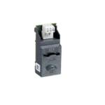
Installing the EtherNet/IP option:
- Susa amandla okulawula kanye nokuphakelwa kwamapayipi kusukela kusiqalisi esithambile.
- Fully pull out the top and bottom retaining clips on the module (A).
- Line up the module with the communication port slot (B).
- Push in the top and bottom retaining clips to secure the module to the soft starter (C).
- Connect Ethernet port 1 or port 2 on the module to the network.
- Faka amandla okulawula kusiqalisi esithambile.

Remove the module from the soft starter:
- Susa amandla okulawula kanye nokuphakelwa kwamapayipi kusukela kusiqalisi esithambile.
- Disconnect all external wiring from the module.
- Fully pull out the top and bottom retaining clips on the module (A).
- Donsela imojuli kude nesiqalisi esithambile.

Ukuxhumana
Soft Starter Connection
The EtherNet/IP Module is powered from the soft starter.
VLT® Compact Starter MCD 201/MCD 202
For the EtherNet/IP Module to accept fieldbus commands, fit a link across terminals A1–N2 on the soft starter.
I-VLT® Soft Starter MCD 500
If the MCD 500 has to be operated in remote mode, input links are required across terminals 17 and 25 to terminal 18. In hand-on mode, links are not required.
ISAZISO
FOR MCD 500 ONLY
Control via the fieldbus communication network is always enabled in local control mode and can be enabled or disabled in remote control mode (parameter 3-2 Comms in Remote). See the VLT® Soft Starter MCD 500 Operating Guide for parameter details.
EtherNet/IP Module Connections
| MCD 201/202 | I-MCD 500 | ||||
 |
 |
||||
| 17 | |||||
| A1 | 18 | ||||
| N2 | |||||
| 25 | |||||
| 2 | 2 | ||||
| 3 | 3 | ||||
| 1 | A1, N2: Stop input | 1 | (Auto-on mode) 17, 18: Stop input25, 18: Reset input | ||
| 2 | EtherNet/IP Module | 2 | EtherNet/IP Module | ||
| 3 | Izimbobo ze-Ethernet ze-RJ45 | 3 | Izimbobo ze-Ethernet ze-RJ45 | ||
Table 4.1 Connection Diagrams
Uxhumano Lwenethiwekhi
Izimbobo ze-Ethernet
The EtherNet/IP Module has 2 Ethernet ports. If only 1 connection is required, either port can be used.
Amakhebula
Suitable cables for EtherNet/IP Module connection:
- Isigaba 5
- Isigaba 5e
- Isigaba 6
- Isigaba 6e
Izinyathelo zokuqapha ze-EMC
To minimize electromagnetic interference, Ethernet cables should be separated from motor and mains cables by 200 mm (7.9 in).
The Ethernet cable must cross the motor and mains cables at an angle of 90°.
| 1 | Ukunikezwa kwezigaba ezi-3 |
| 2 | Ikhebula le-Ethernet |
Illustration 4.1 Correct Running of Ethernet Cables
Ukusungulwa Kwenethiwekhi
The controller must establish communication directly with each device before the device can participate in the network.
Iyakhuluma
Each device in a network is addressed using a MAC address and an IP address and can be assigned a symbolic name associated with the MAC address.
- The module receives a dynamic IP address when it is connected to the network or can be assigned a static IP address during configuration.
- The symbolic name is optional and must be configured within the device.
- The MAC address is fixed within the device and is printed on a label on the front of the module.

Ukucushwa Kwedivayisi
Abagibele Web Iseva
Ethernet attributes can be configured directly in the EtherNet/IP Module using the on-board web iseva.
ISAZISO
The Error LED flashes whenever the module receives power but is not connected to a network. The Error LED flashes throughout the configuration process.
ISAZISO
The default address for a new EtherNet/IP Module is 192.168.0.2. The default subnet mask is 255.255.255.0. The web server only accepts connections from within the same subnet domain. Use the Ethernet Device Configuration Tool to temporarily change the network address of the module to match the network address of the PC running the tool, if required.
To configure the device using the on-board web iseva:
- Attach the module to a soft starter.
- Connect Ethernet port 1 or port 2 on the module to the network.
- Faka amandla okulawula kusiqalisi esithambile.
- Start a browser on the PC and enter the device address, followed by /ipconfig. The default address for a new EtherNet/IP Module is 192.168.0.2.

- Edit the settings as required.
- Click Submit to save the new settings.
- To store the settings permanently in the module, tick Set permanently.
- If prompted, enter username and password.
- Username: Danfoss
- Password: Danfoss
ISAZISO
If an IP address is changed and its record is lost, use the Ethernet Device Configuration Tool to scan the network and identify the module.
ISAZISO
If changing the subnet mask, the server is unable to communicate with the module after the new settings are saved.
Ethernet Device Configuration Tool
Download the Ethernet Device Configuration Tool from www.danfoss.com/drives.
Changes made via the Ethernet Device Configuration Tool cannot be stored permanently in the EtherNet/IP Module. To configure attributes permanently in the EtherNet/IP Module, use the on-board web iseva.
Configuring the device using the Ethernet Device Configuration Tool:
- Attach the module to a soft starter.
- Connect Ethernet port 1 or port 2 on the module to the Ethernet port of the PC.
- Faka amandla okulawula kusiqalisi esithambile.
- Qala Ithuluzi Lokucushwa Kwedivayisi ye-Ethernet.

- Chofoza okuthi Sesha Amadivayisi.
- Isofthiwe isesha amadivayisi axhunyiwe.

- Isofthiwe isesha amadivayisi axhunyiwe.
- To set a static IP address, click Configure and

Ukusebenza
The EtherNet/IP Module is designed for use in a system complying with the ODVA Common Industrial Protocol. For successful operation, the scanner must also support all functions and interfaces described in this manual.
Ukuhlelwa Kwedivayisi
The EtherNet/IP Module is an Adapter class device and must be managed by a Scanner class device over Ethernet.
Ukucushwa Kweskena
I-EDS File
Landa i-EDS file kusuka drives.danfoss.com/services/pc-tools. The EDS file contains all required attributes of the EtherNet/IP Module.
Ngemuva kwe-EDS file is loaded, define the individual EtherNet/IP Module. Input/output registers must be 240 bytes in size and type INT.
Ama-LED
 |
Igama le-LED | Isimo se-LED | Incazelo |
| Amandla | Valiwe | The module is not powered up. | |
| On | The module receives power. | ||
| Iphutha | Valiwe | The module is not powered up or does not have an IP address. | |
| Iyabaneka | Connection timeout. | ||
| On | Duplicate IP address. | ||
| Isimo | Valiwe | The module is not powered up or does not have an IP address. | |
| Iyabaneka | The module has obtained an IP address but has not established any network connections. | ||
| On | Ukuxhumana sekusunguliwe. | ||
| Isixhumanisi x | Valiwe | Alukho uxhumano lwenethiwekhi. | |
| On | Ixhumeke kunethiwekhi. | ||
| TX/RX x | Iyabaneka | Ukudlulisa noma ukwamukela idatha. |
Table 6.1 Feedback LEDs
Izakhiwo zephakethe
ISAZISO
All references to registers refer to the registers within the module unless otherwise stated.
ISAZISO
Some soft starters do not support all functions.
Ukuqinisekisa Ukulawula Okuphephile Nempumelelo
Data written to the Ethernet Module remains in its registers until the data is overwritten or the module is reinitialized. The Ethernet Module does not transfer successive duplicate commands to the soft starter.
Control Commands (Write Only)
ISAZISO
To operate reliably, only 1 bit in byte 0 may be set at a time. Set all other bits to 0.
ISAZISO
If the soft starter is started via fieldbus communications but stopped via the LCP or a remote input, an identical start command cannot be used to restart the soft starter.
To operate safely and successfully in an environment where the soft starter may also be controlled via the LCP or the remote inputs (and fieldbus communications), a control command should be immediately followed by a status query to confirm that the command has been actioned.
| Byte | Kancane | Umsebenzi |
| 0 | 0 | 0 = Stop command. |
| 1 = Start command. | ||
| 1 | 0 = Enable start or stop command. | |
| 1 = Quick stop (coast to stop) and disable start command. | ||
| 2 | 0 = Enable start or stop command. | |
| 1 = Reset command and disable start command. | ||
| 3–7 | Igodliwe. | |
| 1 | 0–1 | 0 = Sebenzisa okokufaka kwesiqalisi esithambile ukuze ukhethe isethi yemoto. |
| 1 = Use primary motor when starting.1) | ||
| 2 = Use secondary motor when starting.1) | ||
| 3 = Igodliwe. | ||
| 2–7 | Igodliwe. |
Table 7.1 Structures Used for Sending Control Commands to the Soft Starter
Ensure that the programmable input is not set to Motor set select before using this function.
Status Commands (Read Only)
ISAZISO
Some soft starters do not support all functions.
| Byte | Kancane | Umsebenzi | Imininingwane |
| 0 | 0 | Uhambo | 1 = Iqhutshiwe. |
| 1 | Isexwayiso | 1 = Isexwayiso. | |
| 2 | Ukugijima | 0 = Unknown, not ready, ready to start, or tripped. | |
| 1 = Starting, running, stopping, or jogging. | |||
| 3 | Igodliwe | – | |
| 4 | Ilungile | 0 = Start or stop command not acceptable. | |
| 1 = Start or stop command acceptable. | |||
| 5 | Control from net | 1 = Always, except in program mode. | |
| 6 | Indawo/Ekude | 0 = Local control. | |
| 1 = Remote control. | |||
| 7 | Kureferensi | 1 = Ukugijima (i-voltage at the motor). | |
| 1 | 0–7 | Isimo | 0 = Unknown (menu open). |
| 2 = Soft starter not ready (restart delay or thermal delay). | |||
| 3 = Ready to start (including warning state). | |||
| 4 = Starting or running. | |||
| 5 = Soft stopping. | |||
| 7 = Trip. | |||
| 8 = Gxumela phambili. | |||
| 9 = Jog reverse. | |||
| 2–3 | 0–15 | Trip/warning code | See trip codes in Table 7.4. |
| 41) | 0–7 | I-Motor current (ibhayithi ephansi) | Okwamanje (A). |
| 51) | 0–7 | I-Motor current (ibhayithi ephezulu) | |
| 6 | 0–7 | Motor 1 lokushisa | Motor 1 thermal model (%). |
| 7 | 0–7 | Motor 2 lokushisa | Motor 2 thermal model (%). |
|
8–9 |
0–5 | Igodliwe | – |
| 6–8 | Inguqulo yohlu lwepharamitha yomkhiqizo | – | |
| 9–15 | Ikhodi yohlobo lomkhiqizo2) | – | |
| 10 | 0–7 | Igodliwe | – |
| 11 | 0–7 | Igodliwe | – |
| 123) | 0–7 | Inombolo yepharamitha eshintshiwe | 0 = No parameters have changed. |
| 1~255 = Index number of the last parameter changed. | |||
| 13 | 0–7 | Amapharamitha | Total numbers of parameters available in the soft starter. |
| 14–15 | 0–13 | Kushintshwe inani lepharamitha3) | Value of the last parameter that was changed, as indicated in byte 12. |
| 14–15 | Igodliwe | – |
| Byte | Kancane | Umsebenzi | Imininingwane |
| 16 | 0–4 | Isimo sokuqala esithambile | 0 = Igodliwe. |
| 1 = Ilungile. | |||
| 2 = Ukuqala. | |||
| 3 = Ukugijima. | |||
| 4 = Ukumisa. | |||
| 5 = Not ready (restart delay, restart temperature check). | |||
| 6 = Iqhutshiwe. | |||
| 7 = Programming mode. | |||
| 8 = Gxumela phambili. | |||
| 9 = Jog reverse. | |||
| 5 | Isexwayiso | 1 = Isexwayiso. | |
| 6 | Iqalisiwe | 0 = Okungaqaliwe. | |
| 1 = Iqaliswe. | |||
| 7 | Ukulawula kwendawo | 0 = Local control. | |
| 1 = Remote control. | |||
| 17 | 0 | Amapharamitha | 0 = Parameters have changed since last parameter read. |
| 1 = No parameters have changed. | |||
| 1 | Ukulandelana kwesigaba | 0 = Ukulandelana kwesigaba esibi. | |
| 1 = Ukulandelana kwesigaba esihle. | |||
| 2–7 | Ikhodi yohambo4) | See trip codes in Table 7.4. | |
| 18–19 | 0–13 | Okwamanje | Isilinganiso se-rms njengamanje kuzo zonke izigaba ezi-3. |
| 14–15 | Igodliwe | – | |
| 20–21 | 0–13 | Okwamanje (% motor FLC) | – |
| 14–15 | Igodliwe | – | |
| 22 | 0–7 | Motor 1 thermal model (%) | – |
| 23 | 0–7 | Motor 2 thermal model (%) | – |
| 24–255) | 0–11 | Amandla | – |
| 12–13 | Isikali samandla | – | |
| 14–15 | Igodliwe | – | |
| 26 | 0–7 | % power factor | 100% = isici samandla esingu-1. |
| 27 | 0–7 | Igodliwe | – |
| 28 | 0–7 | Igodliwe | – |
| 29 | 0–7 | Igodliwe | – |
| 30–31 | 0–13 | Isigaba 1 samanje (rms) | – |
| 14–15 | Igodliwe | – | |
| 32–33 | 0–13 | Isigaba 2 samanje (rms) | – |
| 14–15 | Igodliwe | – | |
| 34–35 | 0–13 | Isigaba 3 samanje (rms) | – |
| 14–15 | Igodliwe | – | |
| 36 | 0–7 | Igodliwe | – |
| 37 | 0–7 | Igodliwe | – |
| 38 | 0–7 | Igodliwe | – |
| 39 | 0–7 | Igodliwe | – |
| 40 | 0–7 | Igodliwe | – |
| 41 | 0–7 | Igodliwe | – |
| 42 | 0–7 | Uhlu lwepharamitha isibuyekezo esincane | – |
| 43 | 0–7 | Parameter list major revision | – |
| 44 | 0–3 | Isimo sokufakwayo kwedijithali | For all inputs, 0 = open, 1 = closed. |
| 0 = Qala. | |||
| 1 = Yima. | |||
| 2 = Hlela kabusha. | |||
| 3 = Okokufaka A | |||
| 4–7 | Igodliwe | – |
| Byte | Kancane | Umsebenzi | Imininingwane |
| 45 | 0–7 | Igodliwe | – |
Table 7.2 Structures Used for Querying the Status of the Soft Starter
- For models MCD5-0053B and smaller, this value is 10 times greater than the value shown on the LCP.
- Product type code: 4=MCD 200, 5=MCD 500.
- Reading bytes 14–15 (changed parameter value) reset byte 12 (changed parameter number) and bit 0 of byte 17 (parameters have changed).
Always read bytes 12 and 17 before reading bytes 14–15. - Bits 2–7 of byte 17 report the soft starter’s trip or warning code. If the value of bits 0–4 of byte 16 is 6, the soft starter has tripped. If bit 5=1, a warning has activated and the soft starter continues operation.
- Power scale functions as follows:
- 0 = Multiply power by 10 to get W.
- 1 = Multiply power by 100 to get W.
- 2 = Power is shown in kW.
- 3 = Multiply power by 10 to get kW.
Soft Starter Internal Register Address
Internal registers within the soft starter have the functions listed in Table 7.3. These registers are not directly accessible via fieldbus.
| Bhalisa | Incazelo | Amabhithi | Imininingwane |
| 0 | Inguqulo | 0–5 | Binary protocol version number. |
| 6–8 | Product parameter list version. | ||
| 9–15 | Product type code.1) | ||
| 1 | Imininingwane yedivayisi | – | – |
| 22) | Inombolo yepharamitha eshintshiwe | 0–7 | 0 = No parameters have changed. |
| 1~255 = Index number of the last parameter changed. | |||
| 8–15 | Total number of parameters available in the soft starter. | ||
| 32) | Kushintshwe inani lepharamitha | 0–13 | Value of the last parameter that was changed, as indicated in register 2. |
| 14–15 | Igodliwe. | ||
| 4 | Isimo sokuqala esithambile | 0–4 | 0 = Igodliwe. |
| 1 = Ilungile. | |||
| 2 = Ukuqala. | |||
| 3 = Ukugijima. | |||
| 4 = Ukumisa. | |||
| 5 = Not ready (restart delay, restart temperature check). | |||
| 6 = Iqhutshiwe. | |||
| 7 = Programming mode. | |||
| 8 = Gxumela phambili. | |||
| 9 = Jog reverse. | |||
| 5 | 1 = Isexwayiso. | ||
| 6 | 0 = Isexwayiso. | ||
| 1 = Iqaliswe. | |||
| 7 | 0 = Local control. | ||
| 1 = Remote control. | |||
| 8 | 0 = Parameters have changed. | ||
| 1 = No parameters have changed.2) | |||
| 9 | 0 = Ukulandelana kwesigaba esibi. | ||
| 1 = Ukulandelana kwesigaba esihle. | |||
| 10–15 | See trip codes in Ithebula 7.4.3) | ||
| 5 | Okwamanje | 0–13 | Isilinganiso se-rms njengamanje kuzo zonke izigaba ezi-3.4) |
| 14–15 | Igodliwe. | ||
| 6 | Okwamanje | 0–9 | Okwamanje (% motor FLC). |
| 10–15 | Igodliwe. |
| Bhalisa | Incazelo | Amabhithi | Imininingwane |
| 7 | Izinga lokushisa lezimoto | 0–7 | Motor 1 thermal model (%). |
| 8–15 | Motor 2 thermal model (%). | ||
| 85) | Amandla | 0–11 | Amandla. |
| 12–13 | Power scale. | ||
| 14–15 | Igodliwe. | ||
| 9 | % Isici samandla | 0–7 | 100% = isici samandla esingu-1. |
| 8–15 | Igodliwe. | ||
| 10 | Igodliwe | 0–15 | – |
| 114) | Okwamanje | 0–13 | Isigaba 1 samanje (rms). |
| 14–15 | Igodliwe. | ||
| 124) | Okwamanje | 0–13 | Isigaba 2 samanje (rms). |
| 14–15 | Igodliwe. | ||
| 134) | Okwamanje | 0–13 | Isigaba 3 samanje (rms). |
| 14–15 | Igodliwe. | ||
| 14 | Igodliwe | – | – |
| 15 | Igodliwe | – | – |
| 16 | Igodliwe | – | – |
| 17 | Inombolo yenguqulo yohlu lwepharamitha | 0–7 | Parameter list minor revision. |
| 8–15 | Parameter list major revision. | ||
| 18 | Isimo sokufakwayo kwedijithali | 0–15 | Kuwo wonke ama-input, 0 = vula, 1 = ivaliwe (ifinyeziwe). |
| 0 = Qala. | |||
| 1 = Yima. | |||
| 2 = Hlela kabusha. | |||
| 3 = Input A. | |||
| 4–15 | Igodliwe. | ||
| 19–31 | Igodliwe | – | – |
Table 7.3 Functions of Internal Registers
- Product type code: 4=MCD 200, 5=MCD 500.
- Reading register 3 (changed parameter value) resets registers 2 (changed parameter number) and 4 (parameters have changed). Always read registers 2 and 4 before reading register 3.
- Bits 10–15 of register 4 report the soft starter’s trip or warning code. If the value of bits 0–4 is 6, the soft starter has tripped. If bit 5=1, a warning has activated and the soft starter continues operation.
- For models MCD5-0053B and smaller, this value is 10 times greater than the value shown on the LCP.
- Power scale functions as follows:
- 0 = Multiply power by 10 to get W.
- 1 = Multiply power by 100 to get W.
- 2 = Power is shown in kW.
- 3 = Multiply power by 10 to get kW.
Parameter Management (Read/Write)
Parameter values can be read from or written to the soft starter.
If output register 57 of the scanner is greater than 0, the EtherNet/IP interface writes all parameter registers to the soft starter.
Enter the required parameter values in the output registers of the scanner. The value of each parameter is stored in a separate register. Each register corresponds to 2 bytes.
- Register 57 (bytes 114–115) corresponds to parameter 1-1 Motor Full Load Current.
- The VLT® Soft Starter MCD 500 has 109 parameters. Register 162 (bytes 324–325) corresponds to parameter 16-13 Low Control Volts.
ISAZISO
When writing parameter values, the EtherNet/IP Interface updates all parameter values in the soft starter. Always enter a valid value for every parameter.
ISAZISO
The numbering of parameter options via fieldbus communications differs slightly from the numbering shown on the LCP. Numbering via the Ethernet Module starts at 0, so for parameter 2-1 Phase Sequence, the options are 1–3 on the LCP but 0–2 via the module.
Amakhodi Ohambo
| Ikhodi | Uhlobo lohambo | I-MCD 201 | I-MCD 202 | I-MCD 500 |
| 0 | Alukho uhambo | ✓ | ✓ | ✓ |
| 11 | Faka uhambo | ✓ | ||
| 20 | Ukugcwala kwezimoto | ✓ | ✓ | |
| 21 | Ukushisa okweqile kosinki wokushisa | ✓ | ||
| 23 | Ukulahlekelwa kwesigaba se-L1 | ✓ | ||
| 24 | Ukulahlekelwa kwesigaba se-L2 | ✓ | ||
| 25 | Ukulahlekelwa kwesigaba se-L3 | ✓ | ||
| 26 | Ukungalingani kwamanje | ✓ | ✓ | |
| 28 | I-overcurrent esheshayo | ✓ | ||
| 29 | I-Undercurrent | ✓ | ||
| 50 | Ukulahlekelwa amandla | ✓ | ✓ | ✓ |
| 54 | Ukulandelana kwesigaba | ✓ | ✓ | |
| 55 | Imvamisa | ✓ | ✓ | ✓ |
| 60 | Inketho engasekelwe (umsebenzi awutholakali ngaphakathi kwe-delta) | ✓ | ||
| 61 | I-FLC iphezulu kakhulu | ✓ | ||
| 62 | Ipharamitha ayikho ebangeni | ✓ | ||
| 70 | Okunhlobonhlobo | ✓ | ||
| 75 | I-Motor thermistor | ✓ | ✓ | |
| 101 | Isikhathi sokuqala eseqile | ✓ | ✓ | |
| 102 | Ukuxhumana kwezimoto | ✓ | ||
| 104 | Internal fault x (where x is the fault code detailed in Ithebula 7.5) | ✓ | ||
| 113 | Ukuxhumana kokuqala (phakathi kwemojuli nesiqalisi esithambile) | ✓ | ✓ | ✓ |
| 114 | Ukuxhumana kwenethiwekhi (phakathi kwemojula nenethiwekhi) | ✓ | ✓ | ✓ |
| 115 | L1-T1 short-circuited | ✓ | ||
| 116 | L2-T2 short-circuited | ✓ | ||
| 117 | L3-T3 short-circuited | ✓ | ||
| 1191) | Isikhathi-seqile (bypass overload) | ✓ | ✓ | |
| 121 | Ibhethri/iwashi | ✓ | ||
| 122 | Isifunda se-thermistor | ✓ |
Table 7.4 Trip Code Reported in Bytes 2–3 and 17 of the Status Commands
For VLT® Soft Starter MCD 500, time-overcurrent protection is only available on internally bypassed models.
Internal Fault X
| Iphutha langaphakathi | Message on LCP |
| 70–72 | Current Read Err. Lx |
| 73 | ATTENTION! Remove Mains Volts |
| 74–76 | I-Motor connection Tx |
| 77–79 | Firing Fail Px |
| 80–82 | I-VZC Yehlulekile Px |
| 83 | Ama-Volts aphansi okulawula |
| 84–98 | Internal fault X. Contact the local supplier with the fault code (X). |
Table 7.5 Internal Fault Code Associated with Trip Code 104
ISAZISO
Only available on VLT® Soft Starters MCD 500. For parameter details, see the VLT® Soft Starter MCD 500 Operating Guide.
Idizayini yenethiwekhi
The Ethernet Module supports star, line, and ring topologies.
Inkanyezi Topology
Kunethiwekhi yenkanyezi, zonke izilawuli namadivayisi axhuma ekushintsheni kwenethiwekhi emaphakathi.

I-Line Topology
In a line network, the controller connects directly to 1 port of the first EtherNet/IP Module. The 2nd Ethernet port of the EtherNet/IP Module connects to another module, which in turn connects to another module until all devices are connected. 
ISAZISO
The EtherNet/IP Module has an integrated switch to allow data to pass through in line topology. The EtherNet/IP Module must be receiving control power from the soft starter for the switch to operate.
ISAZISO
Uma uxhumano phakathi kwamadivayisi angu-2 luphazamisekile, isilawuli asikwazi ukuxhumana namadivayisi ngemva kwendawo yokuphazamiseka.
ISAZISO
Each connection adds a delay to communication with the next module. The maximum number of devices in a line network is 32. Exceeding this number may reduce the reliability of the network.
I-Ring Topology
In a ring topology network, the controller connects to the 1st EtherNet/IP Module via a network switch. The 2nd Ethernet port of the EtherNet/IP Module connects to another module, which in turn connects to another module until all devices are connected. The final module connects back to the switch.
ISAZISO
Iswishi yenethiwekhi kufanele isekele ukulahleka kokutholwa komugqa.
Ama-Topology ahlanganisiwe
Inethiwekhi eyodwa ingabandakanya kokubili inkanyezi nezingxenye zomugqa.

Imininingwane
- Indawo ebiyelwe
- Dimensions, W x H x D [mm (in)] 40 x 166 x 90 (1.6 x 6.5 x 3.5)
- Weight 250 g (8.8 Oz)
- Ukuvikelwa IP20
- Ukukhweza
- Spring-action plastic mounting clips 2
- Ukuxhumana
- Ukuhlanganiswa kwephinikhodi yendlela engu-6 eyisiqalo esithambile
- Contacts Gold …ash
- Networks RJ45
- Izilungiselelo
- IP address Automatically assigned, configurable
- Igama ledivayisi Yabelwe ngokuzenzakalelayo, iyalungiseka
- Inethiwekhi
- Isivinini sesixhumanisi esingu-10 Mbps, 100 Mbps (i-auto-detect)
- I-duplex egcwele
- I-Auto crossover
- Amandla
- Consumption (steady state, maximum) 35 mA at 24 V DC
- Ukuhlehla kwe-polarity kuvikelwe
- Ihlukaniswe nge-galvanically
- Isitifiketi
- I-RCM IEC 60947-4-2
- CE IEC 60947-4-2
- ODVA EtherNet/IP conformance tested
U-Danfoss akakwazi ukwamukela isibopho ngamaphutha angaba khona kumakhathalogi, izincwajana nokunye okuphrintiwe. I-Danfoss igodla ilungelo lokushintsha imikhiqizo yayo ngaphandle kwesaziso. Lokhu kusebenza futhi emikhiqizweni esivele ine-oda inqobo nje uma izinguquko ezinjalo zingenziwa ngaphandle koshintsho olulandelanayo oludingekayo emibhalweni osekuvunyelwene ngayo kakade. Zonke izimpawu zokuhweba kule nto ziyimpahla yezinkampani ezifanele. I-Danfoss kanye nohlobo lwelogo ye-Danfoss yizimpawu zokuthengisa ze-Danfoss A/S. Wonke Amalungelo Agodliwe.
- I-Danfoss A/S
- Amaphuzu 1
- I-DK-6300 Graasten
- vlt-drives.danfoss.com
FAQ
Q: What should I do if I encounter difficulties using the EtherNet/IP Module with third-party products?
A: If you face challenges when using the device with third-party products such as PLCs, scanners, or commissioning tools, contact the relevant supplier for assistance.
Amadokhumenti / Izinsiza
 |
Danfoss MCD 202 EtherNet-IP Module [pdf] Umhlahlandlela wokufaka AN361182310204en-000301, MG17M202, MCD 202 EtherNet-IP Module, MCD 202, EtherNet-IP Module, Module |