
ProPlex Codeclock Timecode Display and Distribution Device
Overview
TMB authorizes its customers to download and print this electronically published manual for professional use only.
TMB prohibits reproduction, modification or distribution of this document for any other purposes, without express written consent.
TMB has confidence in the accuracy of the document information herein but assumes no responsibility or liability for any loss occurring as a direct or indirect result of errors or exclusions whether by accident or any other cause.
PRODUCT DESCRIPTION
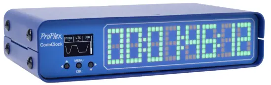
The ProPlex CodeClock is a member of our LTC Device system, which is designed to generate, distribute and monitor timecode. Our rugged, compact mini-enclosure design is perfect for desktop programmers to throw in bag while also being flexible enough to install in a rack with an optional RackMount Kit. With custom color selection on a clean dot-matrix display, the CodeClock is the ultimate tool to synchronize and monitor timecode streams.
MAIN FEATURES
- Large RGB LED matrix clock displays time and changes color depending on status
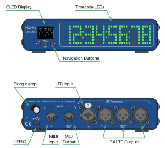
- Receives timecode over LTC (XLR3), MIDI (DIN), or USB MIDI
- Redistributes selected timecode over LTC outputs
- 3x Neutrik XLR3 outputs are transformer-isolated and have adjustable level (-18dBu to +6dBu)
- OLED control panel with an intuitive user interface and waveform display
- Built-in timecode generator capable of running at any standard framerate
- Compact, lightweight, rugged, reliable. Backpack friendly
- Available rackmount kit options
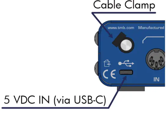
- Powered via USB-C. Cable retainer prevents accidental disconnection
ORDERING CODES
| PART NUMBERS | PROUDCT NAME |
| PPCODECLME | PROPLEX CODECLOCK TIMECODE DEVICE |
| PP1RMKITSS | PROPLEX 1U RACKMOUNT KIT, SMALL, SINGLE |
| PP1RMKITSD | PROPLEX 1U RACKMOUNT KIT, SMALL, DUAL |
| PP1RMKITS+MD | PROPLEX 1U DUAL COMBINATION SMALL + MEDIUM |
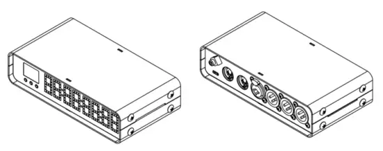
MODEL OVERVIEW
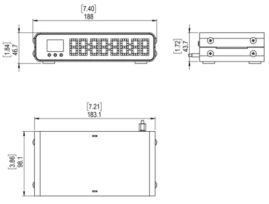
FULL DIMENSIONAL WIREFRAME DRAWINGS
SETUP
Safety Precautions
Please read these instructions carefully.
This user guide contains important information about the installation, usage, and maintenance of this product
- Ensure the device is connected to proper voltage, and that line voltage is not higher than that stated in the device specifications
- Make sure there are no flammable materials close to the unit while operating
- Always use a safety cable when hanging fixture overhead
- Always disconnect from the power source before servicing or fuse replacement (if applicable)
- Maximum ambient temperature (Ta) is 40°C (104°F). Do not operate unit at temperatures above this rating
- In the event of a serious operating problem, stop using the unit immediately. Repairs must be carried out by trained, authorized personnel. Contact the nearest authorized technical assistance center. Only OEM spare parts should be used
- Do not connect the device to a dimmer pack
- Make sure power cord is never crimped or damaged
- Never disconnect power cord by pulling or tugging on the cord
CAUTION! There are no user-serviceable parts inside the unit. Do not open the housing or attempt any repairs yourself. In the unlikely event your unit may require service, please see the limited warranty information at the end of this document
UNPACKING
Upon receipt of the unit, carefully unpack the carton and check the contents to ensure that all parts are present and in good condition. Notify the shipper immediately and retain packing material for inspection if any parts appear to be damaged from shipping or if the carton itself shows signs of mishandling. Save the carton and all packing materials. If a unit must be returned to the factory, it is important that it be returned in the original factory box and packing.
WHAT’S INCLUDED
- ProPlex CodeClock
- USB-C Cable
- Cable retainer clamp
- QR Code downloads card
POWER REQUIREMENTS
The ProPlex CodeClock is powered via USB-C cable connected to any standard 5 VDC wall charger or computer USB port The included cable retainer is a threaded insert which attaches to the USB-C cable. It provides some strain relief and helps prevent accidental disconnection
INSTALLATION
The ProPlex CodeClock enclosure was designed with the touring programmer in mind. We wanted these devices to be lightweight, packable and stackable – so we fitted them with oversized rubber feet to keep them stationary on most surfaces
These units are also compatible with Small RackMount Kits should they need to be semi-permanently mounted for touring applications
RACKMOUNT INSTALLATION INSTRUCTIONS
ProPlex RackMount Kits are available for both Single-Unit and Dual-Unit mounting configurations
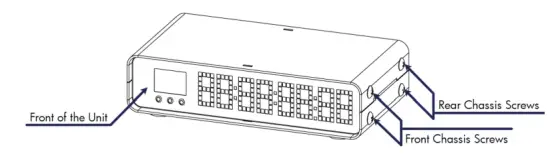
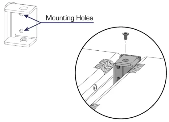
To fasten the rack ears or joiners to the ProPlex PortableMount chassis, you must remove the two chassis screws on each side at the front of the chassis. These same screws are used to securely fasten the RackMount ears and joiners to the chassis
For dual-unit configurations, both sets of front and rear chassis screws will be used
IMPORTANT: Be sure to reinsert the screws into the unit after ears have been removed. Store RackMount Kit in a safe location until needed again. Spare screws are available from TMB if needed
RACKMOUNT INSTALLATION INSTRUCTIONS
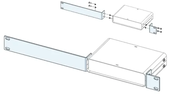
The Single-Unit Small RackMount Kit is comprised of two rack ears, ONE long and ONE short. The diagram below depicts the completed installation of the RackMount Kit. These rack ears are designed to be symmetrical, so that the short and long ears can be interchangeable
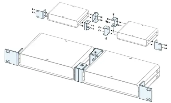
The Dual-Unit Small RackMount Kit has TWO short rack ears plus TWO joiners. The diagram below depicts the completed installation of the RackMount Kit. This configuration requires the TWO center joiners attached at both front and rear
INSTALLING THE DUAL JOINERS
The Dual-Unit Small RackMount Kit includes FOUR joining links and FOUR countersunk flat head screws. These links are designed to nest into each other and are secured with the included screws and threaded holes.
Each link piece is identical. Simply rotate the joining link and line up the installation holes to install on either the left or right side of the corresponding unit.
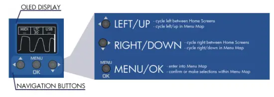
OPERATION
The ProPlex CodeBride can be easily configured with the onboard OLED Display and navigation buttons on the front of the unit
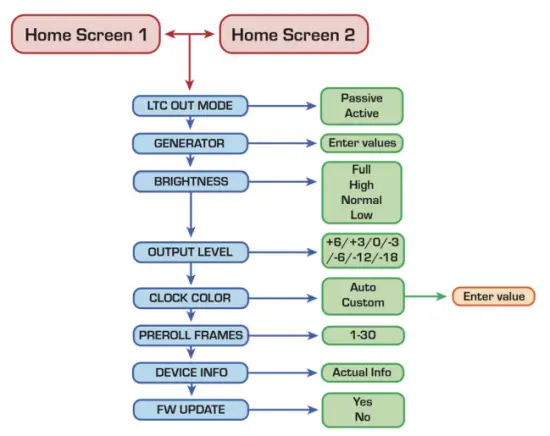
MENU MAP
HOME SCREEN
The CodeClock has 2 HOME SCREENS that display different parameters of incoming timecode streams. Cycle between these screens by pressing either the![]() button
button
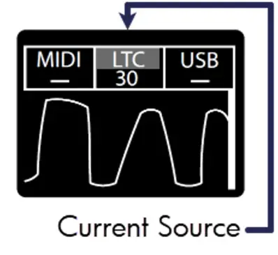
Home Screen 1
The formats and rates of incoming timecode streams show at the top of the screen with the current active source highlighted.
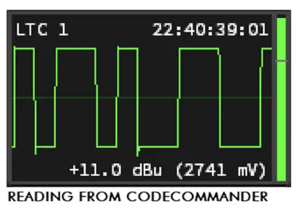
The Oscillogram and voltage level bar underneath indicate signal level from incoming LTC source only
Note: Ideally the LTC IN steam should resemble a square wave with high output level. If level is too low, try increasing the volume at the source to improve the signal
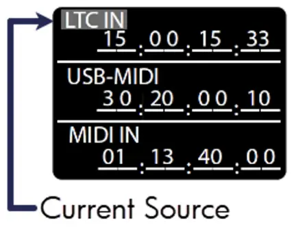
Home Screen 2
This screen displays all sources of timecode that the CodeClock can detect
Whichever source is considered active will be highlighted with a blinking background
Main Menu
The Main Menu can be accessed by pressing the ![]() button and majority of options can be exited via the
button and majority of options can be exited via the![]() button
button
Scroll with the ![]() button and confirm selection with the
button and confirm selection with the![]() button.
button.
Note: Not all menus will fit on the device screen so you will need to scroll to access some menus. The right side of most menu screens will will display a scroll bar which will help indicate the depth of scroll navigation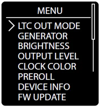
LTC Output Mode
Indicates how LTC timecode is redistributed
Passive Mode: Incoming LTC is physically connected to LTC OUT ports through relay and signal is not altered
Active Mode: LTC timecode has regenerated timing and signal level
Use ![]() then to confirm selection with the
then to confirm selection with the![]() button to cycle between modes. The asterisk indicator will denote the currently selected output level
button to cycle between modes. The asterisk indicator will denote the currently selected output level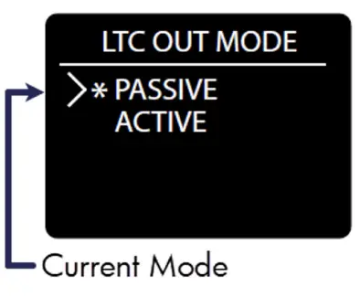 Timecode Generator
The CodeClock can generate clean, high output LTC out of the three isolated XLR3 ports (located on the rear of each unit)
Use the![]() button, then confirm selection with the
button, then confirm selection with the ![]() button to cycle between the various generator options
button to cycle between the various generator options
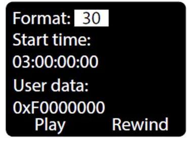
Format: Select between different industry standard FPS rates 23.976, 24, 25, 29.97ND, 29.97DF, and 30 FPS
Start Time: Specify a start time of HH:MM:SS:FF using navigation buttons
User Data: specify user data in 0x00000000 hex format Play, Pause, Rewind: user playback controls for generated timecode.
Note: you must remain on this screen to continuously use the LTC generator. If you exit this screen, the generator will stop automatically, and the current source will change over to the next active source
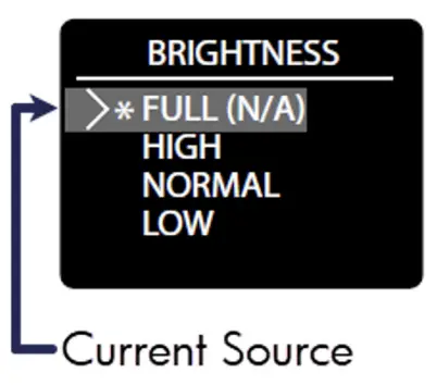
Screen Brightness
There are 4 Brightness settings for the segment display:
FULL HIGH NORMAL LOW
Use the ![]() button, then confirm with the
button, then confirm with the![]() button to choose between the various levels. The asterisk indicator will denote the current screen level
button to choose between the various levels. The asterisk indicator will denote the current screen level
Output Level
Boost or cut the output level from +6 dBu to -12 dBu. Everything outputting via the two isolated XLR3 ports is affected by this level change. This includes:
- Generator output
- Re-transmitted timecode formats from other inputs
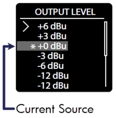
Use the ![]() button, then confirm with the
button, then confirm with the ![]() button to choose between the various output levels. The asterisk indicator will denote the currently selected output level
button to choose between the various output levels. The asterisk indicator will denote the currently selected output level
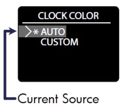
Clock Color
The CodeClock allows the user to customize the display color of the RGB segments or use our ‘auto’ display
Use the ![]() button, then confirm with the
button, then confirm with the ![]() button to choose between the two color modes. The asterisk indicator will denote the currently selected mode
button to choose between the two color modes. The asterisk indicator will denote the currently selected mode
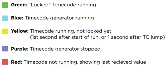
Auto Color: Clock color will change the display color depending on the state of the signal
Color Key:
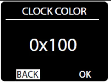
Custom Color
User can customize the RGB color with hex digit values
- Use
 to select and highlight a digit, then press
 to confirm selection
 - Then use to change value (from 0-F) and press again to save.
- As you alter the value, you should see the clock color intensity change in response to your edit
- RGB intensity values are represented by the format: 0x (r-value) (g-value) (b-value)
- Where 0xF00 is full red, 0x0F0 is full green and 0x00F is full blue
- When the desired color is displayed, highlight the OK button on screen and press to save
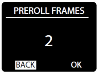
Pre-roll Frames
Pre-roll is the number of valid frames needed to consider the timecode source to be valid and begin forwarding it to the outputs
Use the![]() button to highlight the Pre-roll value, then press
button to highlight the Pre-roll value, then press![]() the button to edit
the button to edit
Use the ![]() button to set the Pre-roll frames (1-30) and to
button to set the Pre-roll frames (1-30) and to![]() save the value
save the value
Note: Active streams will always show the incoming LTC stream starting from the 1st received frame, regardless of Pre-roll settings
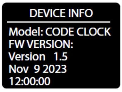
Device Information
Device Info displays status information of the unit.
The information displayed is:
Device Name
FW version
FW Build date
Press![]() to exit
to exit
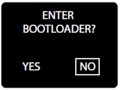
Firmware Updater
Use the![]() button to highlight YES, then press
button to highlight YES, then press![]() the button to enter Bootloader mode. The CodeClock screen should display a note to
the button to enter Bootloader mode. The CodeClock screen should display a note to
“Use USB to Update Firmware” to let you know it is ready
Now the device should respond to updates sent from the Tiva Programmer software – visit tmb.com or email techsupport@tmb.com for information on currently available updates and further instructions
Note: In the case of entering the bootloader accidentally, you must power cycle the device to exit and return to normal operation
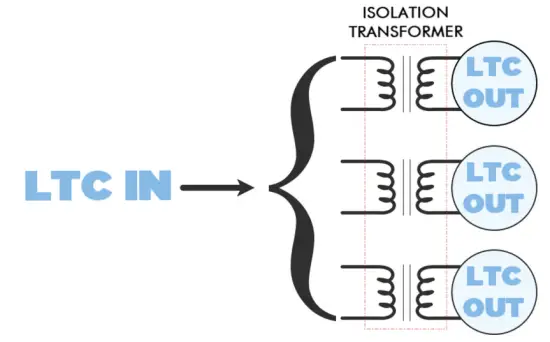
Passive Operation
CodeClock is capable of passive operation, where no power is needed
to pass LTC through from the input to the outputs. We designed CodeClock so that each output uses an isolation transformer to help stabilize passive operation.
Isolation helps to avoid ground loops and other potential signal noise issues between the source and receiver, and among receivers.
However, the implementation of these transformers introduces an attenuation (insertion loss) to the signal at < 1dB typical to 2dB max
This additional signal level loss is normally insignificant and should cause no issue in most cases. BUT if the LTC signal was low to begin with, then the signal might attenuate to a level where it stops working.
Attenuation Recommendations
We always recommended having good headroom when working with timecode. LTC should not be sinusoidal like audio – rather, it is a digital signal that is encoded in a square audio wave
When visualizing LTC, you would generally want to see a high-amplitude square-wave with steep ascents
One fundamental difference between audio and LTC is the acceptable signal level. A “clipped” or overloaded signal is usually something to avoid in audio signals, but it may actually be necessary for accurate LTC timecode synchronization
The goal is to have incoming LTC at 0dBu (775mV), which is also the default output level for active CodeClock and the other LTC family devices
If the incoming LTC signal is low, you may need to boost the level of the sound card in the system. How much may depend on the source
Laptop sound cards
- Built-in sound laptop sound cards are usually unbalanced and often require an adapter from mini-jack to XLR – this results in loss around- 10dBu (316mV)
- It is essential to have PC volume at 100% to avoid sync issues with receives
Professional sound cards
- Pro equipment generally has a much higher output level – usually 70-80%is sufficient for normal operation with LTC
The final recommendation is to always use high-quality cables and adapters. Damaged cables or adapters can unintentionally cause more signal attenuation and lead to issues with LTC stability
CLEANING AND MAINTENANCE
Dust build-up in connector ports can cause performance issues and can potentially lead to further damage during normal wear and tear
CodeClock devices need occasional cleaning to maintain best performance, especially units used in harsher environmental conditions
THE FOLLOWING ARE GENERAL CLEANING GUIDELINES:
- Always disconnect from power before attempting any cleaning
- Wait until unit has cooled and discharged completely before cleaning
- Use vacuum or dry compressed air to remove dust/debris in and around connectors
- Use a soft towel or brush to wipe and buff the chassis body
- To clean the navigation screen, apply isopropyl alcohol with a soft lens cleaning tissue or lint free cotton
- Alcohol pads and q-tips may help remove any grime and residue from navigation buttons
IMPORTANT:
Be sure all surfaces are dry before attempting to power on again
TECHNICAL SPECIFICATIONS
| Part Number | PPCODECLME |
|
Power Connector |
USB-C Connector with cable retainer to prevent accidental power disconnection. Also transmits and receives USB MIDI. |
| MIDI Input Connector | DIN 5-Pin Female |
| MIDI Output Connector | DIN 5-Pin Female |
| LTC Input Connector | Neutrik™ Combination 3-Pin XLR and 1/4” TRS female |
| LTC Output Connectors | Neutrik™ 3-Pin XLR Male |
| Operating Voltage | 5 VDC |
| Power Consumption | 4.5 W Max. |
| Operating Temp. | TBA |
| Dimensions (HxWxD) | 1.72 x 7.22 x 4.42 in [43.7 x 183.5 x 112.3 mm] |
| Weight | 1.4 lbs. [0.64 kg] |
| Shipping Weight | 1.6 lbs. [0.73 kg] |
LIMITED WARRANTY INFORMATION
ProPlex Data Distribution Devices are warranted by TMB against defective materials or workmanship for a period of two (2) years from the date of original sale by TMB.
TMB’s warranty shall be restricted to the repair or replacement of any part that proves to be defective and for which a claim is submitted to TMB before the expiration of the applicable warranty periods.
This Limited Warranty is void if the defects of the Product are the result of:
- Opening the casing, repair, or adjustment by anyone other than TMB or persons specifically authorized by TMB
- Accident, physical abuse, mishandling, or misapplication of the product.
- Damage due to lightning, earthquake, flood, terrorism, war, or act of God.
TMB will not assume responsibility for any labor expended, or materials used, to replace and/or repair the Product without TMB’s prior written authorization. Any repair of the Product in the field, and any associated labor charges, must be authorized in advance by TMB. Freight costs on warranty repairs are split 50/50: Customer pays to ship defective product to TMB; TMB pays to ship repaired product, ground freight, back to Customer.
This warranty does not cover consequential damages or costs of any kind.
A Return Merchandise Authorization (RMA) Number must be obtained from TMB prior to return of any defective merchandise for warranty or non-warranty repair. For repair enquiries, please contact TMB via email at TechSupport@tmb.com or phone at either of our locations below:
TMB US
527 Park Ave.
San Fernando, CA 91340
United States
Tel: +1 818.899.8818
TMB UK
21 Armstrong Way
Southall, UB2 4SD
England
Tel: +44 (0)20.8574.9700
You may also contact TMB directly via email at TechSupport@tmb.com
RETURN PROCEDURE
Please contact TMB and request a repair ticket and Return Merchandise Authorization Number prior to shipping items for repair. Be prepared to provide the model number, serial number, and a brief description of the cause for the return as well as the return shipping address and contact information. Once a repair ticket has been processed, the RMA # and return instructions will be sent via email to the contact on file.
Clearly label any shipping package(s) with ATTN: RMA#. Please return equipment prepaid and in the original packaging whenever possible. DO NOT include cables or accessories (unless advised otherwise). If original packaging is not available, be sure to properly pack and protect any equipment. TMB is not liable for any shipping damage resulting from inadequate packaging by the sender.
Freight call tags will not be issued for shipping repairs to TMB, but TMB will pay the freight for return to the customer if the repair qualifies for warranty service. Non-warranty repairs will undergo a quotation process by the technician assigned to the repair. All associated costs for parts, labor and return shipping must be authorized in writing before any work can be completed.
TMB reserves the right to use its own discretion to repair or replace product(s) and determine the warranty status of any equipment.
CONTACT INFORMATION
LOS ANGELES HEADQUARTERS
527 Park Avenue | San Fernando, CA 91340, USA Tel: +1 818.899.8818 | Fax: +1 818.899.8813 sales@tmb.com
TMB 24/7 TECH SUPPORT
US/Canada: +1.818.794.1286
Toll Free: 1.877.862.3833 (1.877.TMB.DUDE) UK: +44 (0)20.8574.9739
Toll Free: 0800.652.5418
techsupport@tmb.com
LOS ANGELES +1 818.899.8818 LONDON +44 (0)20.8574.9700 NEW YORK +1 201.896.8600 BEIJING +86 10.8492.1587 CANADA +1 519.538.0888 RIGA +371 6389 8886
A full service company providing technical support, customer service, and follow-up.
Providing products and services for the industrial, entertainment, architectural, installation, defense, broadcast, research, telecommunications, and signage industries.Servicing the global market from offices in Los Angeles, London, New York, Toronto, Riga and Beijing.
Documents / Resources
 | Codeclock Timecode Display and Distribution Device |
References
- Beijing.www.tmb.combeijing.www.tmb.com
- TMBtmb.com
- User Manualmanual.tools