TRU COMPONENTS RS232 Multifunction Module
Product Information
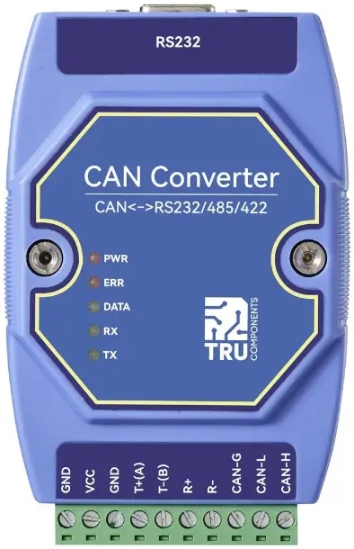
This CAN to RS232/485/422 converter allows for bidirectional conversion between CAN and RS485/RS232/RS422 protocols. It supports various conversion modes including transparent, with logo, protocol, and Modbus RTU conversion. The device features configuration options for interface parameters, AT commands, upper computer parameters, and factory settings restoration. Additionally, it includes power and status indicators, multi-master, and multi-slave functions.
Specifications
- Product: CAN to RS232/485/422 converter
- Item No.: 2973411
Product Usage Instructions
Installation
- Ensure the converter is powered off before installation.
- Connect the appropriate cables to the CAN, RS485/RS232/RS422 interfaces.
- Power on the converter and check the status indicators.
Configuration
To configure the converter:
- Access the interface for parameter configuration.
- Set the desired protocol conversion mode.
- Adjust interface parameters and AT commands as needed.
Operation
Once installed and configured, the converter facilitates seamless data exchange between CAN and RS485/RS232/RS422 protocols. Monitor the status indicators for proper functionality.
FAQ
- Q: Can this converter be used in automotive applications?
A: Yes, this converter is suitable for networking of automobiles and can be utilized in automotive applications. - Q: What should I do if I encounter technical issues?
A: For technical questions or support, please visit www.conrad.com/contact for assistance.
Introduction
Dear customer, Thank you for purchasing this product.
If there are any technical questions, please contact: www.conrad.com/contact
Operating Instructions for download
Use the link www.conrad.com/downloads (alternatively scan the QR code) to download the complete operating in-structions (or new/current versions if available). Follow the instructions on the web page.
Intended use
This product is a small intelligent protocol conversion product. The product uses 8V to 28V wide voltage power sup-ply, integrates 1 CAN-BUS interface, 1 RS485 interface, 1 RS232 interface and 1 RS422 interface, which can realize two-way conversion between CAN and RS485/RS232/RS422 different protocol data. The product supports serial AT command configuration and host computer configuration device parameters and working modes, and supports five data conversion modes including transparent conversion, transparent conversion with logo, protocol conversion, Modbus RTU conversion, and user-defined (user). At the same time, ECAN-401S intelligent protocol converter has the characteristics of small size, easy installation. It has a very high cost performance in the development of CAN-BUS products and data analysis applications. It is an engineering application and project debugging. And reliable assistants for product development.
- It is intended to be mounted on a DIN rail.
- The product is intended for indoor use only. Do not use it outdoors. Contact with moisture must be avoided under all circumstances.
- Using the product for purposes other than those described above may damage the product. Improper use can result in short circuits, fires, or other hazards.
- This product complies with statutory, national and European regulations. For safety and approval purposes, you must not rebuild and/or modify the product.
- Read the operating instructions carefully and store them in a safe place. Always provide these operating instructions when giving the product to a third party.
- All company and product names contained herein are trademarks of their respective owners. All rights reserved.
Features and Applications
Features
- Bidirectional conversion between CAN and RS485/RS232/RS422 different protocol data
- Support transparent conversion, transparent conversion with logo, protocol conversion, Modbus RTU conversion, custom protocol conversion
- Support RS485/RS232/RS422 interface parameter configuration
- Support AT command parameter configuration
- Support the configuration of upper computer parameters
- Support AT command and host computer to restore factory settings
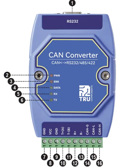
- With power indicator, status indicator and other status indicators
- Multi-master and multi-slave function
Applications
- CAN-BUS network such as industrial control
- Networking of automobiles and railway equipment
- Security and fire protection network
- Underground remote communication
- Public address system
- Parking equipment control
- Smart home, smart building
Delivery content
- CAN to RS485 / RS232 / RS422 converter
- Resistor 120 Ω
- Operating instructions
Description of symbols
The following symbols are on the product/appliance or are used in the text:
 The symbol warns of hazards that can lead to personal injury.
Safety instructions
Read the operating instructions carefully and especially observe the safety information. If you do not follow the safety instructions and information on proper handling in this manual, we assume no liability for any resulting personal injury or damage to property. Such cases will invalidate the warranty/guarantee.
General information
- This product is not a toy. Keep it out of the reach of children and pets.
- Do not leave packaging material lying around carelessly. This may become dangerous playing material for chil-dren.
- Should you have any questions or concerns after reading this document, please contact our technical support or a professional technician.
- Maintenance, modifications and repairs must only be completed by a technician or an authorised repair centre.
Handling
- Please handle the product carefully. Jolts, impacts or a fall even from a low height can damage the product.
Operating environment
- Do not place the product under any mechanical stress.
- Protect the appliance from extreme temperatures, strong jolts, flammable gases, steam and solvents.
- Protect the product from high humidity and moisture.
- Protect the product from direct sunlight.
- Avoid using the product near strong magnetic or electromagnetic fields, transmitter aerials or HF generators. Otherwise, the product may not function properly.
Operation
- Consult an expert when in doubt about the operation, safety or connection of the device.
- If it is no longer possible to operate the product safely, take it out of operation and protect it from any accidental use. DO NOT attempt to repair the product yourself. Safe operation can no longer be guaranteed if the product:
- is visibly damaged,
- is no longer working properly,
- has been stored for extended periods in poor ambient conditions or
- has been subjected to any serious transport-related stresses.
Connected devices
- Always observe the safety information and operating instructions of any other devices connected to the product.
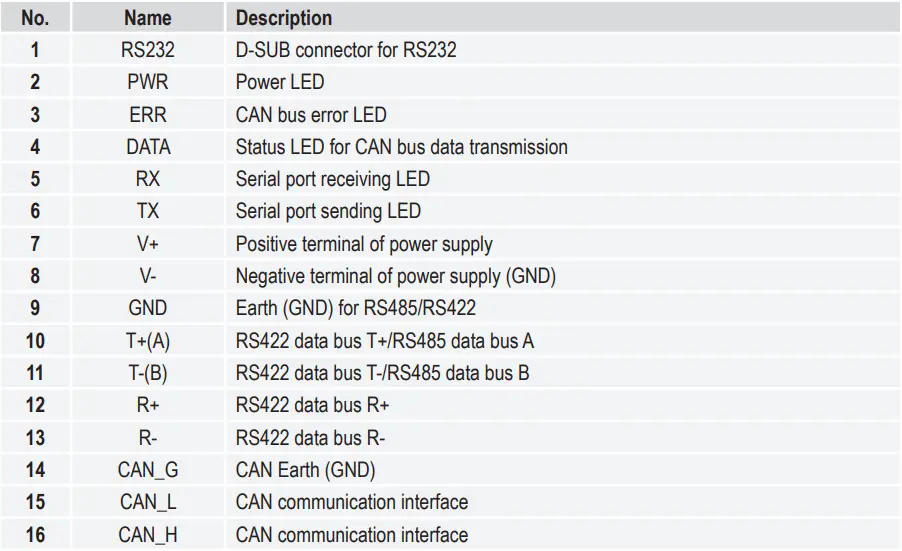
Product overview
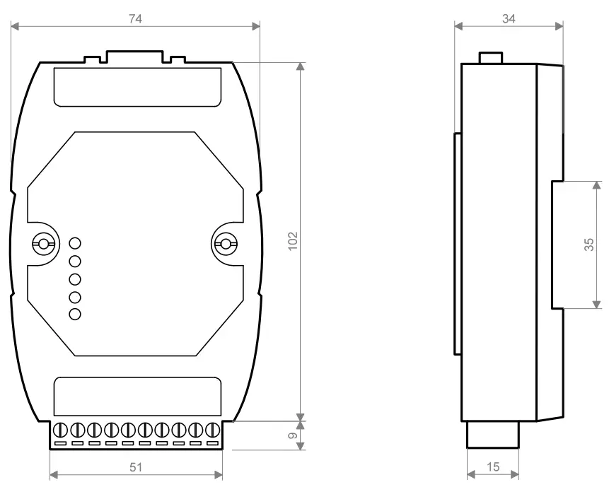
Dimensions
Connection method
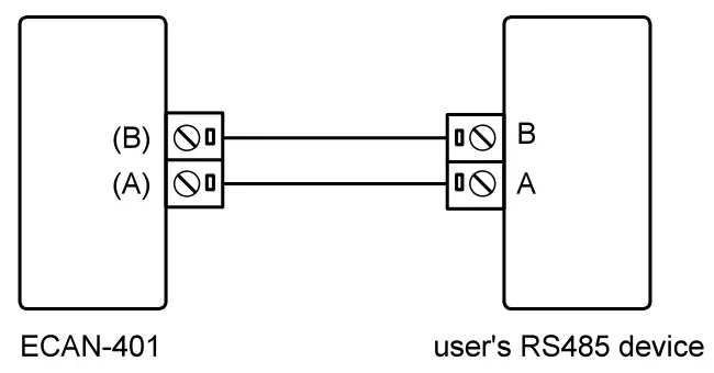
RS485 connection method
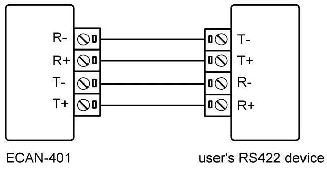
RS422 connection method
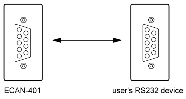
RS232 connection method
CAN connection method
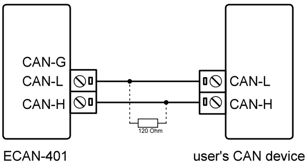
The linear topology is the most commonly used in the CAN bus wiring specification. That is, the two lines of the main trunk branch out branch lines to each node. Both ends of the backbone are equipped with suitable terminal resistors to achieve impedance matching (usually 120 ohms within 2km).
Mode Description
In “transparent conversion” and “format conversion”, one byte of frame information is used to identify some informa-tion of the CAN frame, such as type, format, length, etc. The frame information format is as follows.
Table 1.1 Frame information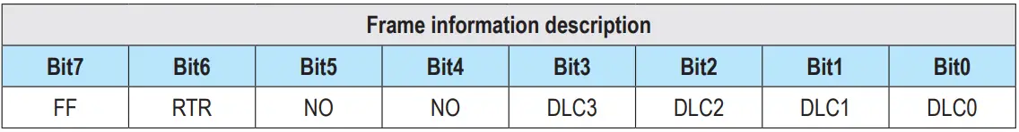
- FF: the identification of standard frame and extended frame, 0 is standard frame, 1 is extended frame
- RTR: identification of remote frame and data frame, 0 is data frame, 1 is remote frame
- NO: not used
- NO: not used
- DLC3~DLC0: Identifies the data length of the CAN message
Data conversion method
ECAN-401S device supports five data conversion methods: transparent conversion, transparent conversion with logo, protocol conversion, MODBUS conversion and custom protocol conversion. Support two-way conversion between CAN and RS485/RS232/RS422.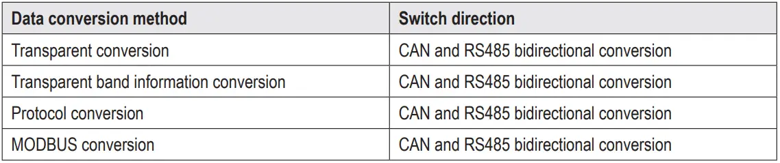
- Transparent conversion mode
Transparent conversion: The converter converts the bus data in one format as it is to the data format of another bus without adding or modifying the data. In this way, the data format is exchanged without changing the data content. For the bus at both ends, the converter is like “transparent”, so it is a transparent conversion.
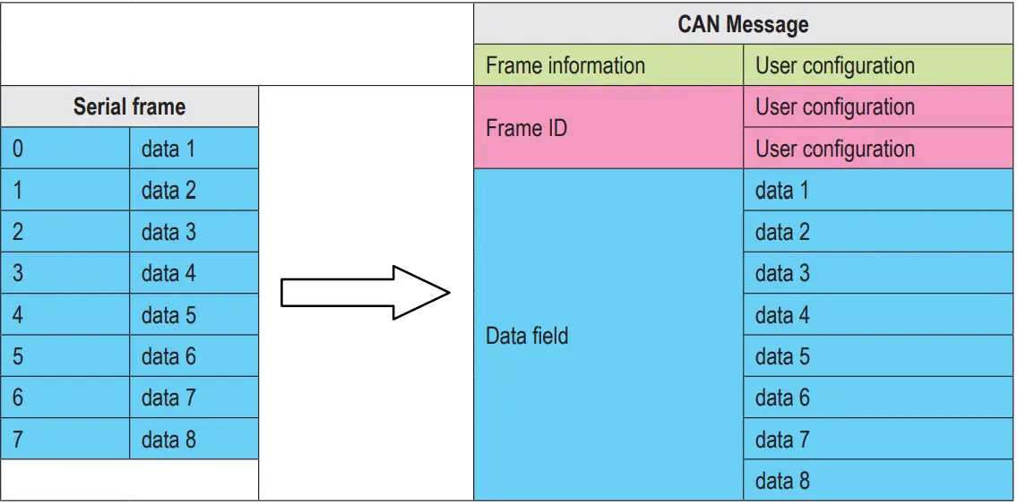
The ECAN-401S device can convert the valid data received by the CAN bus to the serial bus output intact. Similarly, the device can also convert the valid data received by the serial bus to the CAN bus output intact. Realize the trans-parent conversion between RS485/RS232/RS422 and CAN.- Convert serial frame to CAN message
All the data of the serial frame are sequentially filled into the data field of the CAN message frame. After the module detects that there is data on the serial bus, it immediately receives and converts it. The converted CAN message frame information (frame type part) and frame ID come from the user’s prior configuration, and the frame type and frame ID remain unchanged during the conversion process. - Convert serial frame into CAN message (transparent mode)
Conversion example:
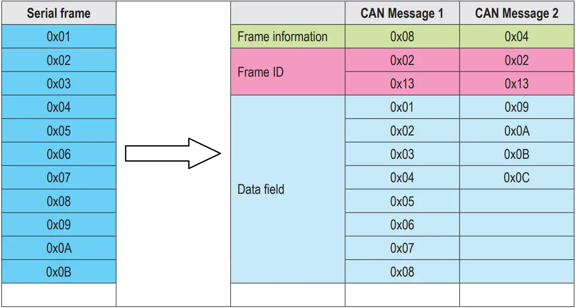
The serial frame is converted into a CAN message (transparent mode).
Assuming that the configuration CAN frame information is “standard frame”, frame ID: “0x0213, serial frame data is 0x01 ~ 0x0C, then the conversion format is as follows. The frame ID of the CAN message is 0x0213 (user configura-tion), frame type: standard Frame (user configuration), the data part of the serial frame will be converted to the CAN message without any modification. - Convert serial frame into CAN message (transparent mode)
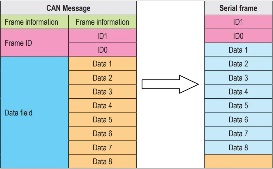
- CAN message to serial frame
During the conversion, all the data in the CAN message data field are sequentially converted into the serial frame. If you check “Enable Frame Information” during configuration, the module will directly fill the “Frame Information” byte of the CAN message into the serial frame. If you check “Enable Frame ID”, then all the “Frame ID” bytes of the CAN message are also filled into the serial frame.
Note: If you want to receive CAN frame information or frame ID on the serial interface, you need to enable the cor-responding function. Only then can you receive the corresponding information.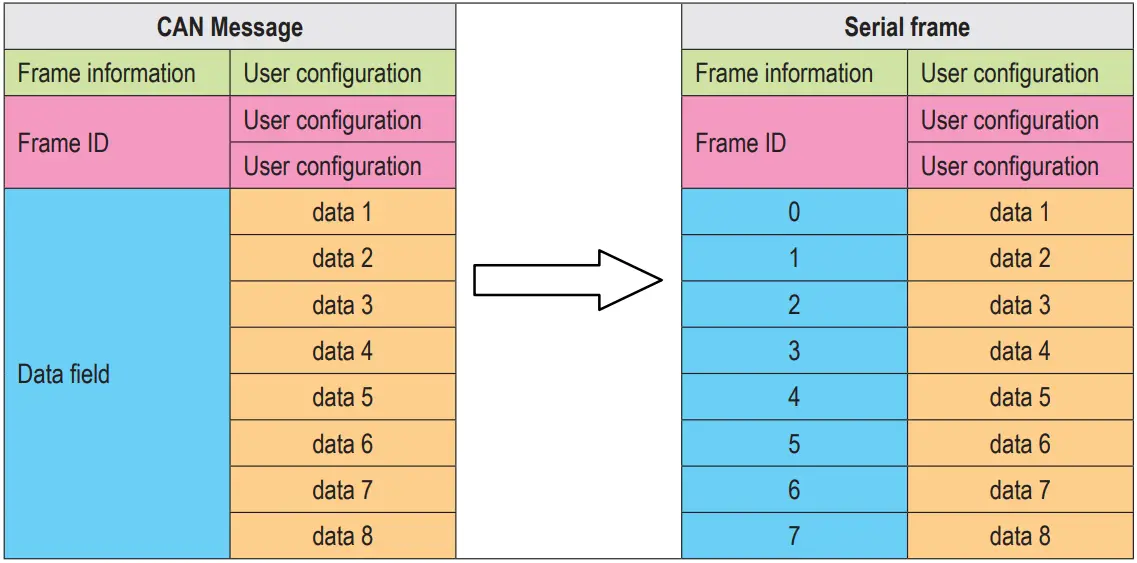
Conversion example:
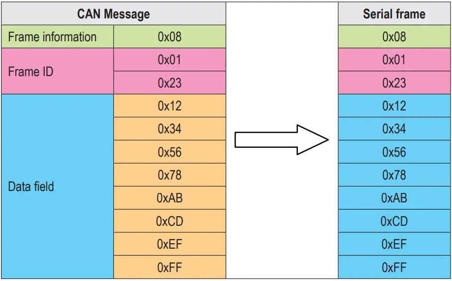
The CAN message “frame information” is enabled and “frame ID” is enabled in this example configuration. Frame ID1: 0x123, frame type: standard frame, frame type: data frame. Conversion direction: two-way. The data is 0x12, 0x34, 0x56, 0x78, 0xab, 0xcd, 0xef, 0xff. The data before and after conversion is as follows: - CAN message is converted into serial frame (transparent mode)
- Convert serial frame to CAN message
- Transparent transmission with logo mode
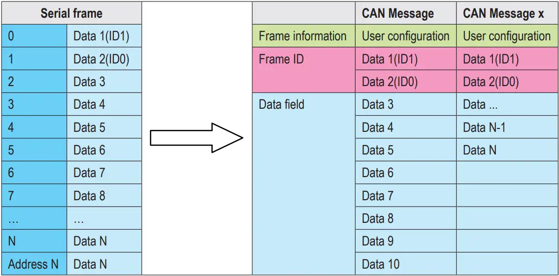
Transparent conversion with identification is a special usage of transparent conversion. The serial frame carries the ID information of the CAN message, and CAN messages with different IDs can be sent as needed. It is helpful for users to construct their own network more conveniently through the module, and use self-defined application protocol. This method automatically converts the ID information in the serial frame into the frame ID of the CAN bus. As long as the module is told in the configuration that the ID information is at the start position and length of the serial frame, the module extracts the frame ID and fills it in the frame ID field of the CAN message when converting, as the CAN when the serial frame is forwarded The ID of the message. When the CAN message is converted into a serial frame, the ID of the CAN message is also converted to the corresponding position of the serial frame.- Convert serial frame to CAN message
The start address and length of the “frame ID” of the CAN message contained in the serial frame in the serial frame can be set by configuration. The starting address ranges from 0 to 7, and the length ranges from 1 to 2 (standard frame) or 1 to 4 (extended frame). During the conversion, the CAN message “frame ID” in the serial frame is converted into the frame ID field of the CAN message according to the prior configuration (if the number of frame IDs is less than the number of frame IDs of the CAN message, then The high byte of the frame ID in the CAN message is filled with 0.), other data is converted in order, if a CAN message has not been converted to the serial frame data, the same ID is still used as the frame of the CAN message ID continues to convert until the serial frame conversion is completed.
Note: If the ID length is greater than 2, the frame type sent by the device will be set as an extended frame. At this time, the frame ID and frame type configured by the user are invalid and are determined by the data in the serial frame. The frame ID range of the standard frame is: 0x000-0x7ff, which are respectively represented as frame ID1 and frame ID0, where frame ID1 is the high byte, and the frame ID range of extended frames is: 0x00000000-0x1fffffff, which are represented as frame ID3, frame ID2, and Frame ID1, frame ID0, among which frame ID3 is the high byte. - Serial frame is converted into CAN message (transparent transmission with identification)
Conversion example:
Serial frame to CAN message (transparent with logo).
CAN configuration parameters configured in this example. Conversion mode: Transparent conversion with logo, start-ing address 2, length 3. Frame type: extended frame, frame ID: no configuration required, conversion direction: two-way. The data before and after conversion is as follows.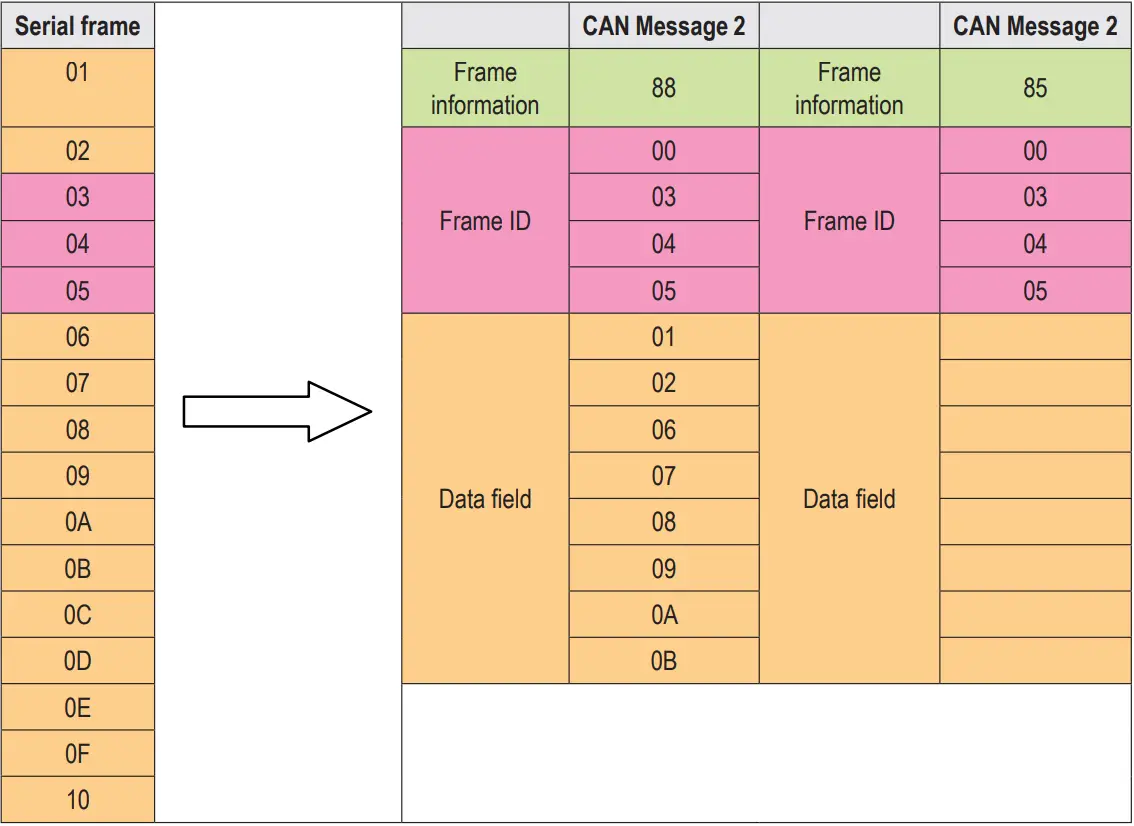
- CAN message to serial frame
For CAN messages, a frame is immediately forwarded after a frame is received. Each time it is forwarded, the ID in the received CAN message is corresponding to the position and length of the CAN frame ID configured in advance in the serial frame. Conversion. Other data are forwarded in order. It is worth noting that the frame format (standard frame or extended frame) of both serial frame and CAN message in application should meet the pre-configured frame format requirements, otherwise it may cause the communication to be unsuccessful. - Convert CAN messages to serial frames
Conversion example:
CAN configuration parameters configured in this example.- Conversion mode: Transparent conversion with logo, starting address 2, length 3.
- Frame type: extended frame, frame type: data frame.
- Conversion direction: two-way. Send identifier: 0x00000123, then the data before and after conversion is as follows.
Example of CAN message conversion to serial frame (transparent with information conversion)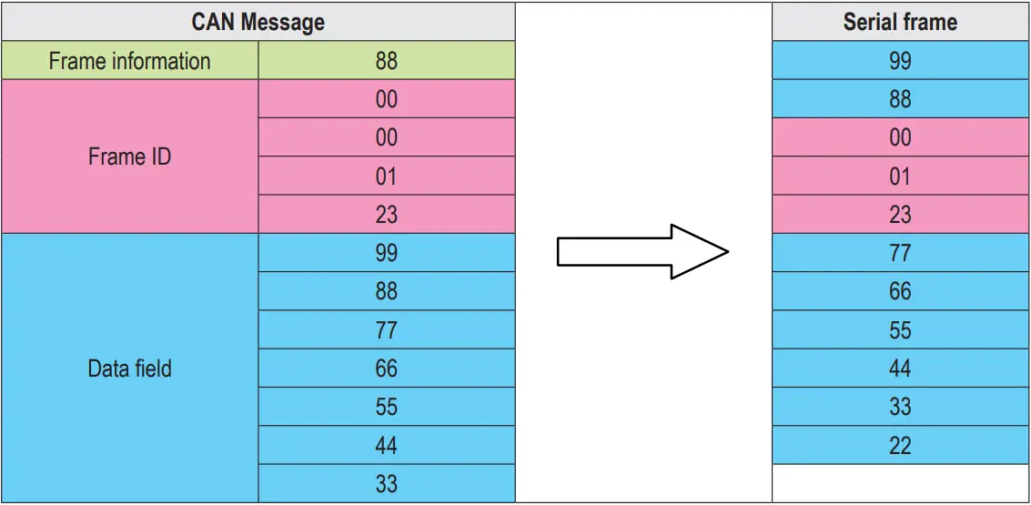
- Convert serial frame to CAN message
- Protocol mode
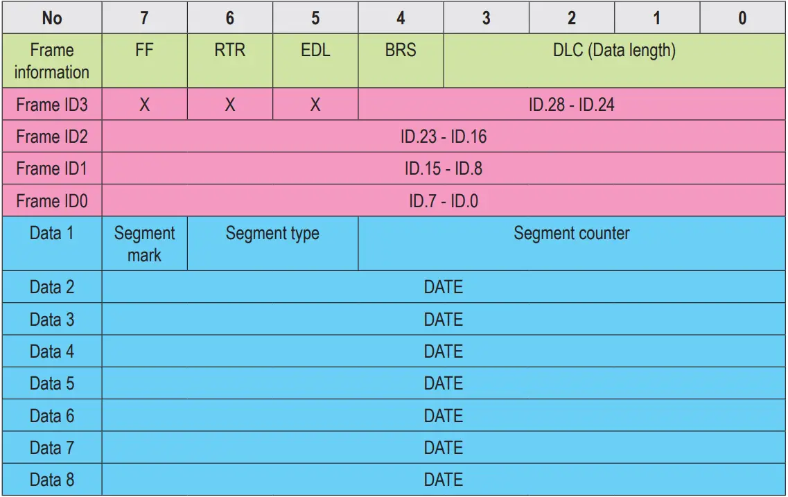
The fixed 13 bytes of CAN format conversion represent a CAN frame data, and the content of 13 bytes includes CAN frame information + frame ID + frame data. In this conversion mode, the CANID set is invalid, because the identifier (frame ID) sent at this time is filled with the frame ID data in the serial frame of the above format. The configured frame type is also invalid. The frame type is determined by the frame information in the format serial frame. The format is as follows:
The frame information is shown in Table 1.1
The length of the frame ID is 4 bytes, the standard frame valid bit is 11 bits, and the extended frame valid bit is 29 bits.
- Convert serial frame to CAN message
In the process of converting a serial frame to a CAN message, in a serial data frame aligned with a fixed byte (13 bytes), if the data format of a certain fixed byte is not standard, the fixed byte length will not be converted. Then con-vert the following data. If you find that some CAN messages are missing after conversion, please check whether the fixed byte length serial data format of the corresponding message does not conform to the standard format. - Convert serial frame to CAN message
When the frame data is converted in CAN format, the length is fixed to 8 bytes. The effective length is determined by the value of DLC3~DLC0. When the effective data is less than the fixed length, it needs to be filled with 0 to the fixed length.
In this mode, it is necessary to pay attention to the serial data format in strict accordance with the fixed byte format to successfully convert. The CAN mode conversion can refer to the example (CAN format conversion standard frame example). When converting, first ensure that the frame information is correct and the data length indicates No errors, otherwise no conversion will be performed.
Conversion example:
Serial frame to CAN message (protocol mode).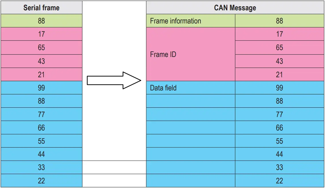
CAN configuration parameters configured in this example.
Conversion mode: protocol mode, frame type: extended frame, conversion direction: two-way. Frame ID: No need to configure, the data before and after conversion is as follows. - Serial frame to CAN message (protocol mode)
- Convert serial frame to CAN message
- Modbus mode
Modbus protocol is a standard application layer protocol, which is widely used in various industrial control occasions. The protocol is open, with strong real-time performance, and good communication verification mechanism. It is very suitable for occasions with high communication reliability requirements. The module uses the standard Modbus RTU protocol format on the serial port side, so the module not only supports the user to use the Modbus RTU protocol, but also the module. It can directly interface with other devices that support Modbus RTU protocol. On the CAN side, a simple and easy-to-use segmented communication format is developed to realize Modbus communication. A method for segmenting and reorganizing information with a length greater than the maximum data length of a CAN message. “Data 1” is used to segment identification data. , The transmitted Modbus protocol content can start from the “data 2” byte, if the protocol content is greater than 7 bytes, then the remaining protocol content will continue to be converted according to this segmented format until the conversion is completed. When there is no other data on the CAN bus, the frame filter may not be set. The communication can be completed. When there are other data on the bus, a filter needs to be set. Distinguish the source of data received by the device. According to this approach. It can realize the communication of multiple hosts on a bus. The data transmitted on the CAN bus does not require a CRC validation method. Data validation on the CAN bus already has a more complete validation method. In this mode, the device supports Modbus verification and forwarding, not the Modbus master or slave, and the user can communicate ac-cording to the Modbus protocol.- Segmented transmission protocol
A method for segmenting and reorganizing information with a length greater than the maximum data length of a CAN message. In the case of a CAN message, “Data 1” is used to segment identification data. The format of the segment message is as follows, and the content of the transmitted Modbus protocol is sufficient. Starting from the “data 2” byte, if the protocol content is greater than 7 bytes, the remaining protocol content will continue to be converted in this segmented format until the conversion is completed.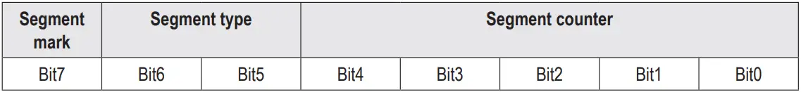
- Segmented message tag: indicates whether the message is a segmented message. If this bit is 0, it means a sepa-rate message, and it is 1 it means Belongs to a frame in the segmented message.
- Segment type: Indicate whether it is the first paragraph, the middle paragraph or the last paragraph.
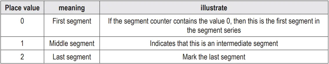
- Segment counter: The mark of each segment indicates the sequence number of the segment in the entire message. If it is the number of segments, the value of the counter is the number. In this way, it is possible to verify whether any segments are missing when receiving. 5Bit is used in total, and the range is 0~31.
- Convert serial frame to can message
The serial interface adopts the standard Modbus RTU protocol, so the user frame only needs to comply with this protocol. If the transmitted frame does not conform to the Modbus RTU format, the module will discard the received frame without converting it. - CAN message to serial frame
For the Modbus protocol data of the CAN bus, there is no need to do cyclic redundancy check (CRC16), the module receives according to the segmentation protocol, and automatically adds the cyclic redundancy check (CRC16) after receiving a frame analysis, and converts it into Modbus RTU frame to send To the serial bus. If the received data does not conform to the segmentation protocol, the group of data will be discarded without conversion.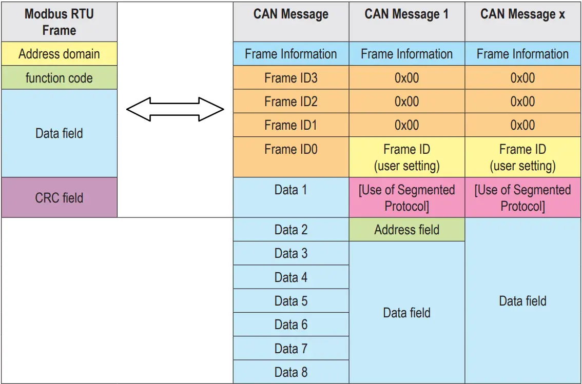
Conversion example: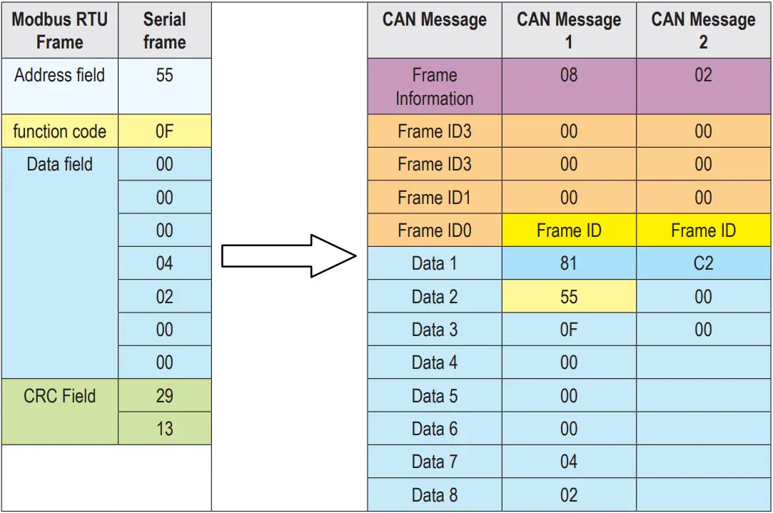
- Segmented transmission protocol
- Custom protocol mode
It must be a complete serial frame format that conforms to the custom protocol, and it must contain all the serial frames in the mode configured by the user.
There is content, except for the data field, if the content of other bytes is wrong, this frame will not be sent success-fully. The content of the serial frame: frame header, frame length, frame information, frame ID, data field, frame end.
Note: In this mode, the frame ID and frame type configured by the user are invalid, and the data will be forwarded ac-cording to the format in the serial frame.- Convert serial frame to CAN message
The serial frame format must conform to the specified frame format. Because the CAN frame format is based on messages, the serial frame format is based on byte transmission. Therefore, in order to allow users to use CAN-bus conveniently, the serial frame format is moved closer to the CAN frame format, and the start and end of a frame are specified in the serial frame, that is, the “frame head” and “frame end” in the AT command. , Users can configure by themselves. Frame length refers to the length from the beginning of the frame information to the end of the last data, excluding the end of the serial frame. Frame information is divided into extended frames and standard frames. The standard frame is fixed as 0x00, and the extended frame is fixed as 0x80, which is different from transparent con-version and transparent conversion with identification. In custom protocol conversion, regardless of the data length contained in the data field of each frame How much, the content of the frame information is fixed. When the frame type is a standard frame (0x00), the last two bytes of the frame type represent the frame ID, with the high order first; when the frame information is an extended frame (0x80), the last 4 bytes of the frame type represent the frame ID, where High ranking first
Note: In the custom protocol conversion, regardless of the data length contained in the data field of each frame, the frame information content is fixed. It is fixed as standard frame (0x00) or extended frame (0x80). The frame ID needs to conform to the ID range, otherwise the ID may be wrong.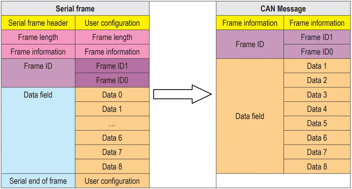
- Convert CAN message to serial frame
CAN bus message receives a frame and then forwards a frame. The module will convert the data in the CAN message data field in turn, and at the same time add frame header, frame length, frame information and other data to the serial frame, which is actually a serial frame Transfer the reverse form of CAN message.
Convert CAN messages to serial frames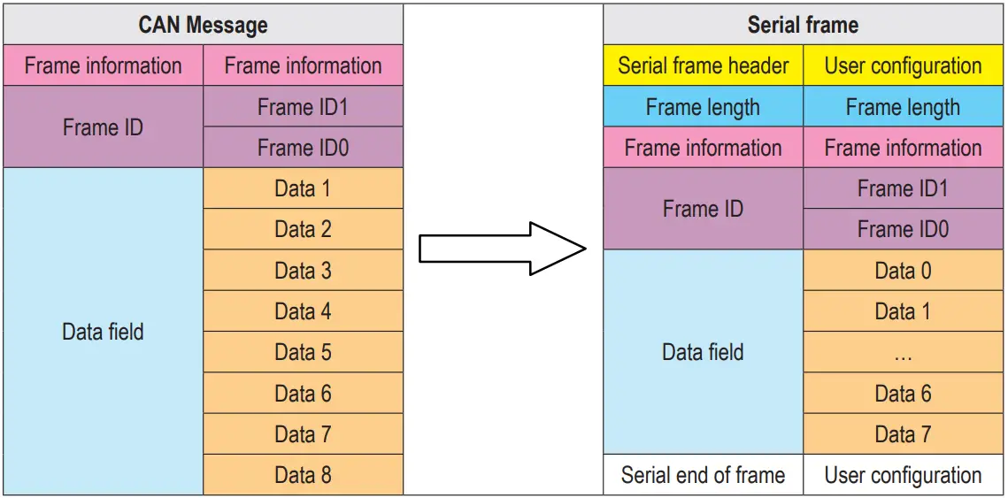
Conversion example:
Serial frame to CAN message (custom protocol).
CAN configuration parameters configured in this example.
Conversion mode: custom protocol, frame header AA, frame end: FF, conversion direction: bidirectional.
Frame ID: No need to configure, Frame type: No need to configure, the data before and after conversion is as follows. CAN message to serial frame: the reverse form of serial frame to CAN message.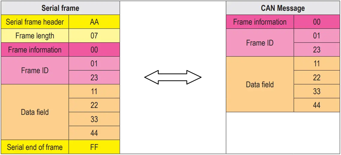
- Convert serial frame to CAN message
AT Command
- Enter AT command mode: send +++ via serial port, send AT again within 3 seconds, the device will return AT MODE, then enter AT command mode.
- If there is no special instruction, all subsequent AT command operations need to add “\r\n”.
- All examples are performed with the command echo function turned off.
- After setting the parameters, you need to restart the device to make the set parameters take effect.
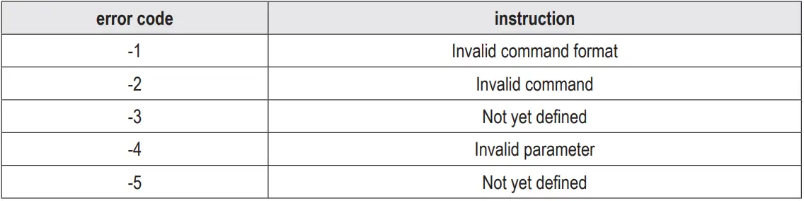
Error code table:
Default parameters:
- Enter AT command

Example:
Send: +++ // no line break
Send: AT // no line break
Response: <CR><LF>AT MODE<CR><LF> - Exit AT command
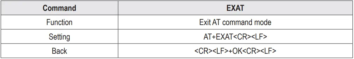
Example:
Send: AT+EXAT\r\n
Response: <CR><LF>+OK<CR><LF> - Query version
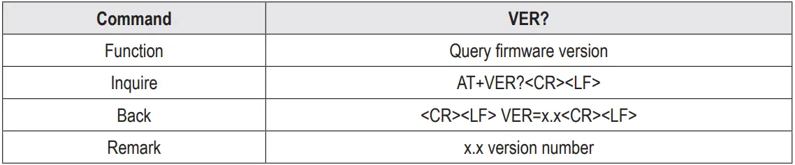
Example:
Send: AT+VER? \r\n
Response: <CR><LF> VER=x.x <CR><LF> - Restore default parameters
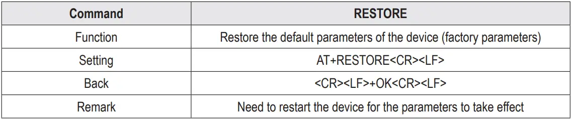
Example:
Send: AT+RESTORE \r\n
Response: <CR><LF>+OK<CR><LF> - Echo settings
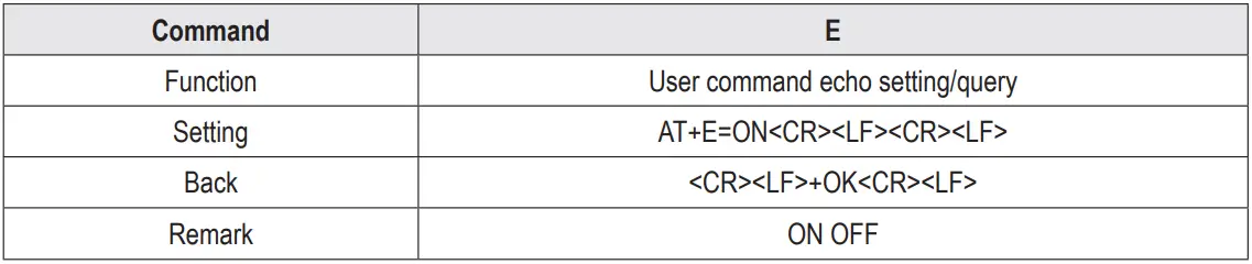
Example:
set up:
Send: AT+E=OFF\r\n
Response: <CR><LF>+OK<CR><LF> Inquire:
Send: AT+E?\r\n
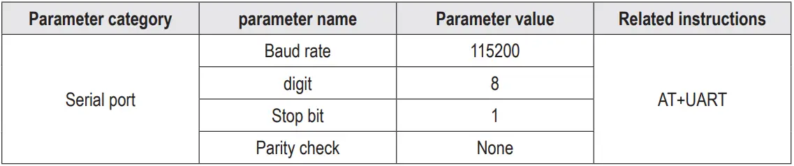
Response: <CR><LF>+OK<CR><LF> - Serial port parameters
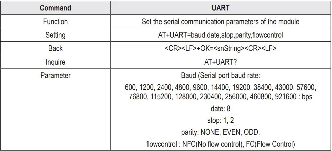
Example:
set up:
Send: AT+UART=115200,8,1,EVEN,NFC\r\n
Response: <CR><LF>+OK<CR><LF>
Inquire:
Send: AT+UART?\r\n
Response: <CR><LF>+OK<CR><LF> AT+UART=115200,8,1,EVEN,NFC <CR><LF> - Setting/Querying CAN Information
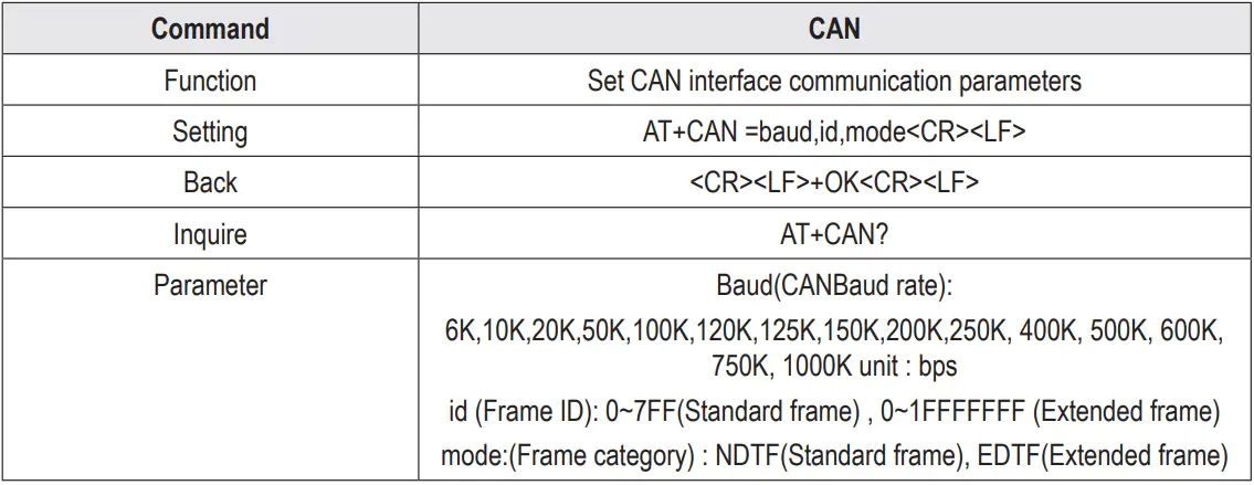
Example:
set up:
Send: AT+CAN=100,70,NDTF\r\n
Response: <CR><LF>+OK<CR><LF>
Inquire:
Send: AT+ CAN?\r\n
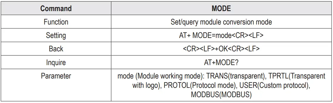
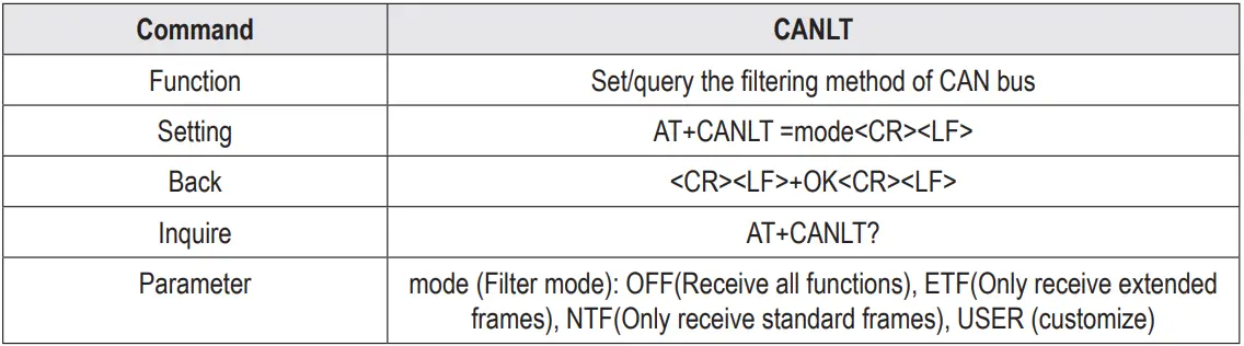
Response: <CR><LF>+OK<CR><LF> AT+CAN=100,70,NDTF <CR><LF> - Setting/Querying Module Conversion Mode
Example:
set up:
Send: AT+CANLT=ETF\r\n
Response: <CR><LF>+OK<CR><LF>
Inquire:
Send: AT+ CANLT?\r\n
Response: <CR><LF>+OK<CR><LF> AT+CANLT=ETF<CR><LF> - Set/query the filtering mode of the CAN bus
Example:
set up:
Send: AT+MODE=MODBUS\r\n
Response: <CR><LF>+OK<CR><LF>
Inquire:
Send: AT+ MODE?\r\n
Response: <CR><LF>+OK<CR><LF>AT+MODE=MODBUS <CR><LF> - Set/query frame header and frame end data
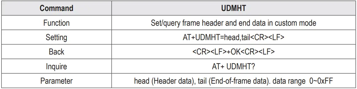
Example:
Settings: Set the frame header data to FF and the frame end data to 55 Send: AT+UDMHT=FF,55 \r\n
Response: <CR><LF>+OK<CR><LF>
Inquire:
Send: AT+UDMHT?\r\n
Response: <CR><LF>+OK<CR><LF> AT+UDMHT=FF,55<CR><LF> - Setting/Querying Identification Parameters
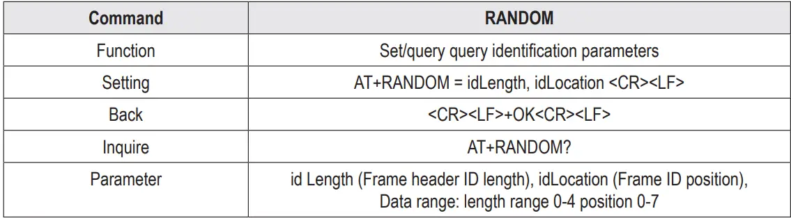
Example:
Settings: Set the frame ID length to 4, position 2
Send: AT+RANDOM=4,2 \r\n
Response: <CR><LF>+OK<CR><LF>
Inquire:
Send: AT+ RANDOM?\r\n
Response: <CR><LF>+OK<CR><LF> AT+RANDOM=4,2 <CR><LF> - Setting/Querying Identification Parameters
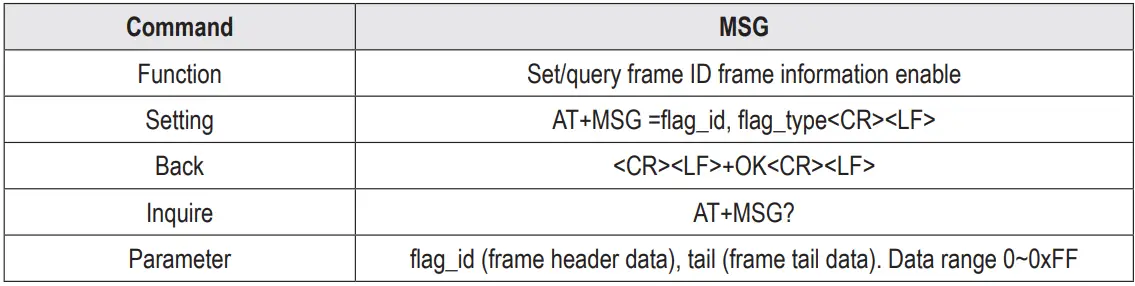
Example:
Settings: enable frame ID, frame information
Send: AT+MSG=1,1 \r\n
Response: <CR><LF>+OK<CR><LF>
Inquire:
Send: AT+ MSG?\r\n
Response: <CR><LF>+OK<CR><LF> AT+MSG=1,1<CR><LF> - Set/query transmission direction
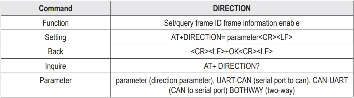
Example:
Setting: Only convert serial port data to can bus
Send: AT+DIRECTION=UART-CAN\r\n
Response: <CR><LF>+OK<CR><LF>
Inquire:
Send: AT+ DIRECTION?\r\n
Response: <CR><LF>+OK<CR><LF> AT+DIRECTION=UART-CAN <CR><LF> - Setting/Querying Filter Parameters
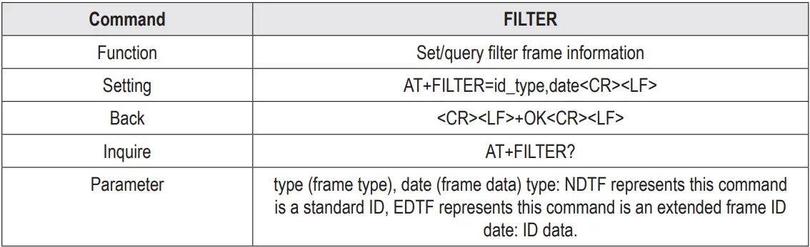
Example:
Settings: Set frame filtering parameters: standard frame ID, 719
Send: AT+LFILTER=NDTF,719 \r\n
Response: <CR><LF>+OK<CR><LF>
Query: Will return all IDs that have been set
Send: AT+ FILTER?\r\n
Response: <CR><LF>+OK<CR><LF> AT+LFILTER=NDTF,719 <CR><LF> - Delete the filter parameters that have been set
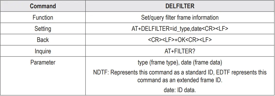
Example:
Setting: delete filter parameter: standard frame 719
Send: AT+DELFILTER=NDTF,719 \r\n
Response: <CR><LF>+OK<CR><LF>
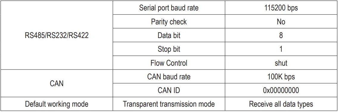
Factory default parameters
Cleaning and maintenance
Important:
- Never use aggressive detergents, rubbing alcohol or other chemical solutions, as these could damage the housing or even impair the functioning of the product.
- Do not immerse the product in water.
- Disconnect the product from the power supply.
- Clean the product with a dry, fibre-free cloth.
Disposal
 This symbol must appear on any electrical and electronic equipment placed on the EU market. This symbol indicates that this device should not be disposed of as unsorted municipal waste at the end of its service life.
Owners of WEEE (Waste from Electrical and Electronic Equipment) shall dispose of it separately from unsorted municipal waste. Spent batteries and accumulators, which are not enclosed by the WEEE, as well as lamps that can be removed from the WEEE in a non-destructive manner, must be removed by end users from the WEEE in a non-destructive manner before it is handed over to a collection point.
Distributors of electrical and electronic equipment are legally obliged to provide free take-back of waste. Conrad provides the following return options free of charge (more details on our website):
- in our Conrad offices
- at the Conrad collection points
- at the collection points of public waste management authorities or the collection points set up by manufacturers or distributors within the meaning of the ElektroG
End users are responsible for deleting personal data from the WEEE to be disposed of.
It should be noted that different obligations about the return or recycling of WEEE may apply in countries outside of Germany.
Technical data
Power supply
- Power supply……………………………8 – 28 V/DC; 12 or 24 V/DC power supply unit recommended
- Power input………………………………18 mA at 12 V (Standby)
- Isolation value…………………………..DC 4500V
Converter
- Interfaces …………………………………CAN bus, RS485, RS232, RS422
- Ports ………………………………………. Power supply, CAN bus, RS485, RS422: Screw terminal block, RM 5.08 mm; RS232: D-SUB socket 9-pin
- Mounting………………………………….DIN rail
Miscellaneous
- Dimensions (W x H x D)…………….approx. 74 x 116 x 34 mm
- Weight ……………………………………. approx. 120 g
Ambient Conditions
- Operating/storage conditions………-40 to +80°C, 10 – 95% RH (non-condensing)
This is a publication by Conrad Electronic SE, Klaus-Conrad-Str. 1, D-92240 Hirschau (www.conrad.com).
All rights including translation reserved. Reproduction by any method, e.g. photocopy, microfilming, or the capture in electronic data processing systems require the prior written approval by the editor. Reprinting, also in part, is prohibited. This publication represent the technical status at the time of printing.
Copyright 2024 by Conrad Electronic SE.
Documents / Resources
 |
TRU COMPONENTS RS232 Multifunction Module [pdf] Instruction Manual RS232 Multifunction Module, RS232, Multifunction Module, Module |