FCS Multilog2 Multi Channel Data Logger
Specifications
- Product Name: Multilog 2
- Device Type: Data Logger
- Models Covered: ML/*/*/* PT/*/*/* EL/*/*/* WL/*/*/*
- Additional Models: WL series models for WITS systems
- Software Tool: IDT (Installation and Diagnostic Tool)
INTRODUCTION
The “Multilog2” is a multi-purpose data logger device. Several models are available. Please contact your sales representative for help with selection of an appropriate model for your application.
HWM also provides a software tool, known as “IDT” (“Installation and Diagnostic Tool”) for logger setup and test. (See also section 1.6).
MODELS COVERED, DOCUMENTATION AND SUPPORT OF PRODUCT
This user-guide covers the following models:
Model Number Device Description
| Model Number | Device Description |
| ML/*/*/* | Multilog2 logger device. |
| PT/*/*/* | Pressure Transient2 logger device. |
| EL/*/*/* | Enhanced Network2 logger device. |
| WL/*/*/* | Multilog2 logger device (models for use in WITS systems).
– Additional information for WL series models can be found in the supplementary user guide. |
This user-guide should be read in conjunction with:
| Document Number | Document Description
Safety Warnings and Approvals Information (for Multilog2). IDT (PC version) user-guide. Multilog2 (Supplement for models supporting WITS protocol) IDT (app for mobile devices) user-guide. |
| MAN-147-0003 | |
| MAN-130-0017 | |
| MAN-147-0017 | |
| MAN-2000-0001 |
This user-guide provides details of the logger operation and how to install the product. Also refer to any user-guides or datasheets for sensors that are being used with the logger.
Read the relevant parts of the IDT user-guide for guidance on how to confirm settings or modify the set-up of your logger. This includes:
- Details of setup of sensor channels and making recordings of the data.
- Logger settings for the delivery of measurement data to a server.
- Logger setup for additional messaging features, such as alarms.
Note: The system periodically has new features and changes released, thus you may observe slight changes from the diagrams and features shown in this manual. Installed features and functionality can vary from device to device, therefore always refer to the menus and screens of any setup tool to determine which features are available on your logger device.
HWM provides support for logger devices by means of our customer support webpages: https://www.hwmglobal.com/help-and-downloads/
Should you have any questions that are not covered by this manual or online help, please contact the HWM Technical Support team on +44 (0) 1633 489479, or email cservice@hwm-water.com
SAFETY CONSIDERATIONS
Before continuing, carefully read and follow the information in the “Safety Warnings and Approvals Information” document supplied with the product. This provides general safety information.
Retain all documents for future reference.
Before using this product, make a risk assessment of the installation site and expected work activity. Ensure suitable protective clothing is worn and working practises are followed during installation and any maintenance.
WARNING: When this equipment is being used, installed, adjusted, or serviced this must be undertaken by suitably qualified personnel familiar with the construction and operation of the equipment and the hazards of any utility network.
OPERATING TEMPERATURE
Refer to the logger Datasheet or your sales representative for guidance on the storage and operating temperature range of the device. Ensure the unit is within the operating temperature range prior to installation or setup.
USE OF CELLULAR NETWORKS – IMPORTANT NOTES
Availability of SMS
Most Multilog2 models include the ability to communicate to a server via use of the cellular data network. This is usually via the regular data network (which gives internet access). Alternatively, the SMS (Short Message Service) messaging can be used; in most cases this will be as a fall-back if the logger is temporarily unable to access the regular data network. If configured for SMS use, the logger uses the available 2G network.
Important: 2G (GPRS) services, which carry the SMS messaging system, are slowly being turned off around the globe. Once 2G is switched off, the SMS services available within the logger will no longer be able to function. Unless deactivated in the logger settings, the logger will continue to try, wasting battery power. Therefore, check with your cellular network operator for their switch off date before setting the logger to use the SMS backup service or any other feature requiring SMS use.
To deactivate the use of the SMS system, any related SMS settings must be removed (switched off or deleted). Refer to the IDT User Guide for details of SMS settings.
Any modified settings must be saved to the logger.
Note: For use of SMS services, both the logger and the cellular network provider must support SMS. In addition, the SIM card fitted inside the logger must support SMS use. (Check with your SIM supplier if required).
Logger identity when using SMS
When using the cellular data network, the logger identity is included with the data within the message. However, when using the SMS system, the identity is the calling number (from the SIM card). Thus, when using any SMS services, these two numbers (IDT setting of logger telephone number and SIM telephone number) must match.
VIEWING DATA
To view logger data remotely, a viewing tool (website) is used. Various websites are available. Each website presents data associated with logger installation sites. The choice of website will depend on the type of sensors used and their application.
Data from your logger can also be viewed locally using IDT during a site visit.
Refer to the training materials available for your viewing tool and also the IDT user-guide for further information.
IDT – SOFTWARE TOOL (FOR LOGGER PROGRAMMING AND TESTS)
A software tool, known as “IDT” (Installation and Diagnostic Tool), is available for checking or making adjustments to the logger setup and also for testing the logger operation on-site.
Choosing which version to use
The IDT software tool provides a user-interface to the logger. It can be used for checking or making adjustments to the logger settings and for testing the logger operation within its installed site. Prior to IDT being able to perform these functions, it has to ‘connect to’ the logger; this simply means that the two end devices (logger software and IDT software) are able to communicate with each other over a working communications path.
IDT is available in three versions:
- IDT for PCs having a Windows-operating system.
- IDT for mobile devices (phones and tablets) having an Android operating system.
- IDT for mobile devices (phones and tablets) having an (Apple) iOS system.
The latter two are referred to as the ‘IDT app’, whereas the first is referred to as ‘IDT (PC)’ or ‘IDT (Windows)’.
It is recommended to install and use the IDT app version whenever possible; it covers most types of HWM loggers. There are, however, a small number of situations where loggers or logger/sensor combinations that (at the time of writing) require the use of the IDT (PC) tool. Refer to section 8 for further details of which sensors or features require IDT (PC), as applicable to the loggers listed in section 1.1.
IDT (PC VERSION)
Refer to the IDT (PC version) User-Guide (MAN-130-0017) for details of how to prepare your PC for communicating with the logger. The user-guide also gives details of how to use IDT with various logger settings.
IDT APP (MOBILE DEVICE VERSION)
Refer to the IDT app User-Guide (MAN-2000-0001) for details of how to prepare your mobile device (Android-based Tablet) for communicating with the logger. The user-guide also gives details of how to use the IDT app with various logger settings.
OVERVIEW
LOGGER DEVICE OVERVIEW
PHYSICAL FEATURES & CONNECTOR IDENTIFICATION
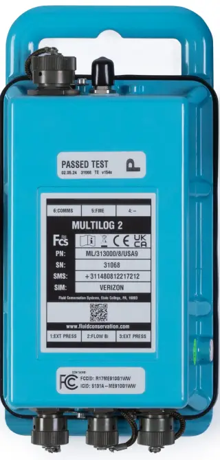
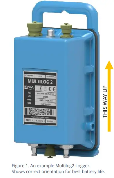
The Multilog2 logger family is flexible in design and can be built to suit a variety of uses. It has a metal enclosure and is of a waterproof construction, using a seal to keep out water.
An example is shown in Figure 1.
The logger is powered by a non-rechargeable Lithium battery. The life of the battery can vary with its orientation; refer to Figure 1 for the orientation that will give best battery life.
The top of the logger includes a handle, used for carrying the unit. It also provides a convenient way of hanging the unit in its correct orientation using wall-mounted brackets or other fixing methods.
Various labels are present on the logger. These include:
- The nameplate label, which includes the logger part-number, its serial number, and an ‘SMS number’ (an identifier for the logger, in the form of a telephone number).
- Interface identification labels.
The logger has waterproof electrical connectors for attaching sensors and the antenna. These can be present on two surfaces (top and bottom). The interfaces installed, and their position, will vary between model-number supplied. Follow the labels to identify interfaces.
A pressure interface may also employ a built-in pressure transducer with a quick-release connector. This is for direct connection to a pipe (or hose).
EXTERNAL BATTERY (OPTION)
Most Multilog2 models have a connector that allows an External Battery to be connected. These provide the logger with additional power capacity.
An example is shown in Figure 2.
Various battery capacities are available.
Always use HWM supplied batteries to ensure compatibility and safety. Ensure the cable supplied with the battery is suitable for the external power connector fitted to your logger. (6-pin and 10-pin connector versions are available. See also section 2.7).
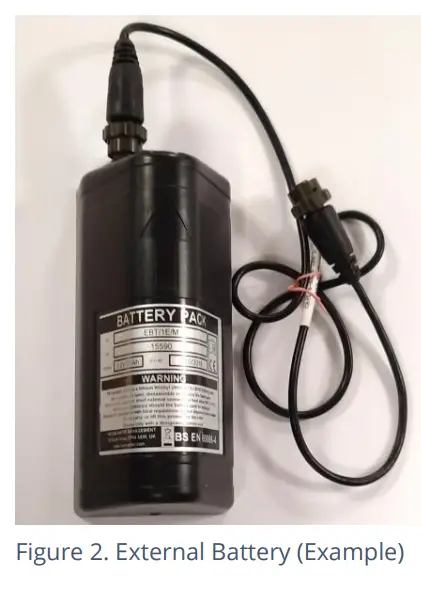
(For situations where the use of an external battery is required, seek the advice of your HWM representative).
LOGGER OPERATION
- The logger software is designed to minimize battery use and thereby prolong the expected battery life. However, battery life is also affected by user-programmablesettings. The user is advised to set the logger tasks and sample frequencies to the minimum requirements of the intended use in order to manage battery power effectively.
- Where supplied, the external battery power is used to extend the battery life of the logger or to allow more frequent communications with the host server.
- The logger is normally shipped from the factory in an inactive state (referred to as
‘shipping mode’, or ‘sleep mode’) to preserve the life of the battery. - When activated (see section 3), the logger will initially go into the state of “Waiting” (for a short time). Then it will go into the state of “Recording” and begin repetitive logging of measurements from the various sensors fitted to the unit, according to its configuration and settings.
- The logger operates using two time periods, known as the “sample period” and the “log period”. It will sample the sensors at the sample rate to create temporary measurement samples; this is a repetitive background task. After taking several measurement samples, some statistical functions can be optionally applied to produce a datapoint that is logged (saved) at the log rate; these form the recorded (logged) measurements and are saved into an area of memory which is referred to as the “primary recording”. The log period is always a multiple of the sample period.
- If the logger has the feature enabled, it can also be set to occasionally save additional data into a “secondary recording” memory area (see section 2.4), (e.g., data sampled at a higher frequency, such as by using the “sample period” rather than the “log period”).
Note: This is not available on all supplied units and must be arranged through your sales representative before placing an order; it has implications concerning expected battery life of the unit.
The logger will also have daily tasks at set times, such as uploading its unsent data over the internet. When sending data, the logger waits to receive confirmation from the server that the data was received without error; If confirmation is not received, it will re-send the data at the next call-in time.
The logger can be programmed to monitor data for certain patterns or conditions and can send a message if it should detect a match. Commonly, this is used for setting a condition that can be an indication of an “alarm”. The message can be sent to either the server (the usual destination) or another device.
ENHANCED LOGGING (OPTIONS)
Section 2.3 gave a description of logger operation that is available as standard on most Multilog2 logger models; The logger normally samples data at the set sample period, and records datapoints at the set log period. However, certain models offer options for making additional recordings (of logged data) at higher-than-normal sampling rates. The additional data is recorded within the “secondary recording” memory area.
These features are sometimes referred to as “Enhanced Network” logging and “Pressure Transient” logging; Collectively they are referred to as “Fast Logging”. The ‘Enhanced Network’ and ‘Pressure Transient’ loggers (both being based on the Multilog2 design), have the named option available as standard.
Note: The feature can only be installed by the factory at the time of build. The options must therefore be specified at the time of ordering, along with the required maximum sampling rate.
Additional sampling has implications for power consumption and may require the use of external batteries to meet the required service life.
The fast-logging features of the logger can be disabled during logger setup. Where enabled, the logger has two strategies for dealing with memory becoming full. Either the fast logging will stop, or older data can be over-written. Make the selection you require during setup.
Not all sensor types are able to work at high sampling frequencies. The feature is therefore usually set to work with analogue sensors, such as a pressure transducer.
Fast logging is frequently used to monitor pressure fluctuations on the water supply network.
For Multilog2, ‘Enhanced Network’ logging and ‘Pressure Transient’ logging are mutually exclusive settings (only one can be used). Each has a different operation.
Enhanced Network Logging:
- This option allows certain events to create a secondary recording.
- The recording will be made at the background sampling rate.
- The recording can be a single channel or can include additional channels (if the sensor can cope with the speed).
- The maximum sampling rate is limited to a frequency of 1Hz.
Pressure Transient Logging:
- This option allows certain events to create a secondary recording.
The logger has additional memory due to the amount of data required to be stored. - The recording will be made at a sampling rate of 1Hz or one of a selection of higher frequencies, up to 25Hz.
- On Multilog2, up to two channels can be used. Each of these must be for a pressure sensor. The sensors must be allocated to channel 1, or channels 1 & 2.
The recordings can be set to occur either at specific times or in response to various alarm events or a change in a Status Input (i.e., triggered by a switch output from external equipment).
SERVER INTEGRATION – STORING AND VIEWING DATA
The Multilog2 logger includes an interface (referred to as a modem) that provides access to the internet via the cellular mobile communications network. A SIM card is used to give access of the network.
Measurement data is initially stored within the logger, until the next call-in time. The data can then be uploaded to the server using an encrypted format. Typically, the server used to receive and store the data will be an HWM DataGate server, although other servers may be used in conjunction with HWM software.
The logger data may be viewed using a viewing portal which has access to the data stored on the server. (Refer to the relevant user guide for details of how your data viewer can be used to view the logger data).
Note: Multilog2 loggers supporting WITS protocol behave differently to the above.
These loggers do not use DataGate but communicate with a WITS Master Station. The data can be viewed only by use of the WITS system.
DATAGATE SERVER / DATA VIEWING PORTALS
When integrated with HWM’s DataGate server, the logger’s measurement data can be stored centrally and made available to users via a viewing portal (website). The data storage server can handle receipt and storage of data from a single unit, or from an entire fleet of loggers.
Viewing Primary Recordings:
The data from your logger(s) can be viewed remotely / graphically by anyone authorized to do so, with a suitable user account (and password) using a standard web-browser.
HWM has a selection of websites that can be used to view logger data. The best choice of website depends upon the type of sensors used with the logger.
A website with a generic data viewer can show data graphically, but only for one logger at a time, installed on one site.
A website which can show a fleet of loggers, each having the same type of sensor, can often present data in a more meaningful way to the user, along with useful supplementary information (e.g., a map showing the logger locations). Thus, a website may give a picture of the current status of many sites at one time.
Refer to the IDT user guide or sensor user-guide for details of which viewing portal is most appropriate to use. Alternatively, discuss this issue with your HWM representative.
The DataGate server can also forward any alarms received from the logger to all users that have subscribed to them; one logger alarm message can therefore be distributed to multiple DataGate users.
DataGate can also (by arrangement with your sales representative) be used to export logger data to other servers.
Some administrative setup of the server and of the viewing portal is normally required to facilitate receiving, storing, and presenting logger data correctly. (Setup of and use of the DataGate system (or any other server) are not covered by this user guide).
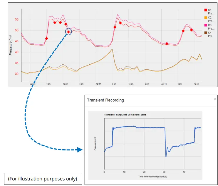
Viewing Secondary Recordings:
For sites which have logger models with Fast logging included, secondary recordings may have been made. These are also stored on the server.
Your data viewer will have a means of displaying secondary recordings.
It may, for example, show a marker on the main trace to indicate the point where fast data is available (e.g., where a transient occurred). Click the marker to provide a close-up view of the transient.
Viewing location fix (GPS track):
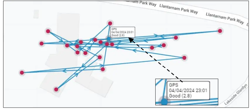
For logger models that include GPS position fix capability, the server will provide a facility to track the location history of the logger. Details of the GPS location fix can be found, typically by selecting one of the shown points. The quality of the location fix will be shown as a number. (This is known as a DOP value. Refer to the table below).
| Value | Grade | Description |
| <2 | Excellent
/ ideal |
Excellent confidence in location fix accuracy. |
| 2-5 | Good | Good confidence in location accuracy / reliable result. |
| 5-10 | Moderate | Moderate confidence in location accuracy. A more open view of the sky or acquisition period may improve. |
| 10-20 | Fair | Low confidence level in location accuracy. Indicates a very rough estimate of location. |
| >20 | Poor | Poor confidence of accuracy of location. The measurement should be discarded. |
INSTALLATION ACCESSORIES
Accessories (antenna and brackets for mounting the unit) are available to suit various installation situations; discuss availability with your HWM representative.
COMMUNICATIONS INTERFACES AND PROGRAMMING CABLES
To communicate with the Multilog2 logger, a programming cable is required. There are two connector options available in the logger family for making this connection (10-pin or 6-pin); only one of these alternatives will be fitted. Use a programming cable that matches the connector type on the logger.
On Multilog2, the connectors used for communications are frequently shared; they also include the connections required for fitting an external battery (see section 2.2). Because of space limitations, the label may not indicate this (e.g., It may simply be labeled “COMMS”).
A typical connector used for communications and its matching communications cable is shown in Figure 3.
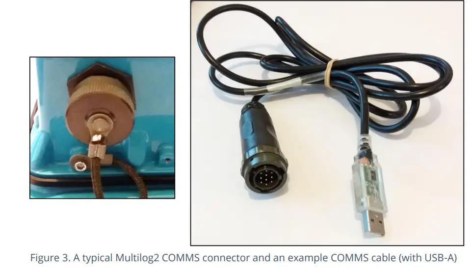
The connector of the communications cable will only include the pins required for communications purposes.
To use the communications cable, temporarily remove any existing connector, and re-connect it when finished. Alternatively, an adaptor (Y-cable) can be inserted to be able to support the logger using both functions together.
Attach the Comms cable to the logger, and then complete the connection to the IDT host using one of the methods described in section 2.8.
Examples of suitable programming cables are given below:
- 10-pin : COM AEUSB (USB to RS232 comms cable).
- CABA2075 (direct USB comms cable).
- 6-pin : CABA8585 (direct USB comms cable).
COMPLETING THE COMMUNICATIONS PATH
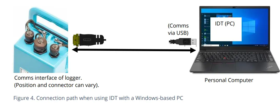
For IDT to communicate with the logger, first select the appropriate cable and connect it to the COMMS connector of the logger, as described in section 2.7. The USB-A end of the programming cable should be used to connect to the IDT host by using one of the following methods:
IDT – USED WITH A PC (& WINDOWS).
Prior to use, the PC should have the IDT (PC version) programming tool installed.
The USB-A end should be plugged directly into a USB-A port of the PC (or to USB-B or USB-C port via a suitable adaptor). Refer to Figure 4.
IDT APP – USED WITH A TABLET (ANDROID) / USB OPTION
Certain Android-based Tablet devices (which must have an available USB port) are able to use this method. (For latest information about known compatible devices, contact your HWM representative).
Prior to use, the mobile device should have the IDT app software installed.
The USB-A end should be plugged directly into a USB-A port of the tablet (or to a USB-B or USB-C port via a suitable adaptor). Refer to Figure 5.
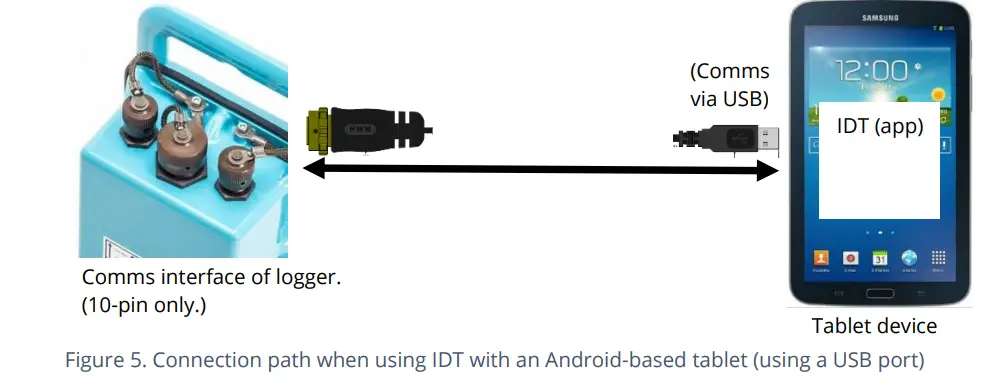
This connection method is only compatible with a 10-pin logger connector and using the COM AEUSEB (USB to RS232) comms cable, or CABA2080 (USB to RS232) Y-Cable.
IDT APP – USED WITH A MOBILE PHONE OR TABLET / BLUETOOTH OPTION
Certain mobile phone or tablet devices (which must be Android or iOS-based and support Bluetooth radio) are able to use this method. (For latest information about known compatible devices, contact your HWM representative).
Prior to use, the mobile device should have the IDT app software installed.
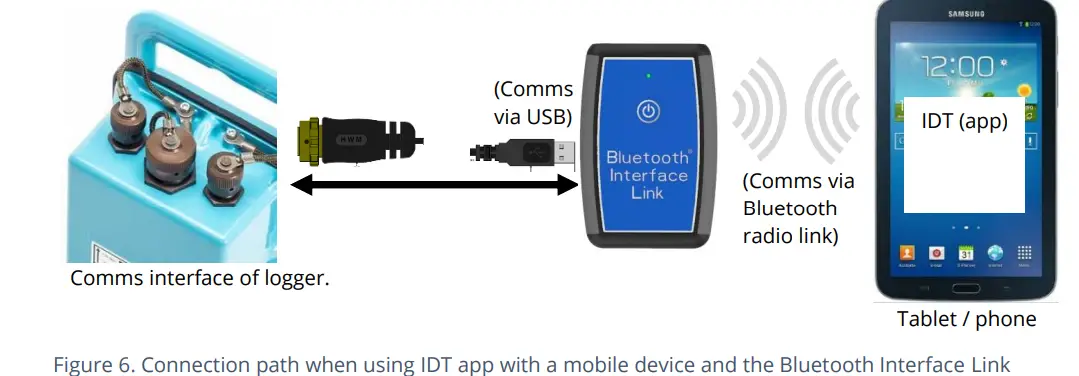
The connection path (refer to Figure 6) makes use of a communications adapter known as the HWM ‘Bluetooth Interface Link’. Connect the logger end of the communications cable to the logger. Then the USB-A end of the communications cable should be plugged into the USB-A port of the Bluetooth Interface Link unit. The device should be turned on during use. The IDT app is required to be paired to the Bluetooth Interface Link unit prior to communication with the logger. The Bluetooth Interface Link handles protocol translations and flow control of messages between the logger
(via the comms cable) and the radio link.
ACTIVATING THE LOGGER AND COMMUNICATIONS LINK
The communications interface is always monitored for activity and the logger will usually respond, unless it is busy communicating to the cellular network.
LOGGER ACTIVATION PROCESS (FOR FIRST-TIME USE)
When shipped from the factory, the unit is in ‘shipping mode’ (deactivated; not logging or calling in). This mode is suitable for shipping or long-term storage. To use the logger, it must first be activated.
The process for doing this depends upon the logger setting for logging re-activation. Various setting options are available (specified time, upon connection of an external battery, upon the activation of a magnetic switch, ‘immediately’).
Most loggers are set to start ‘immediately’ upon having their settings read by IDT and then saved back to the unit.
Once activated, the logger will initially go into the state of ‘Waiting’ (for a short time). Then it will enter a status of ‘recording’, where it is executing its repetitive logging functions.
The method depends on which version of IDT is being used:
- For IDT (PC), the user can do this manually (even if no program changes are required). (Refer to the IDT user-guide for the steps required to read the logger program and then to save it back to the unit using the ‘Setup Device’ button).
- For the IDT app, the user can also do this manually via a Start Device’ button. In addition, the app will check for potential issues whenever the user makes a controlled disconnection of the logger from the app, including a check for a logger that is not yet activated / recording.
Before leaving site, check that the logger has been correctly set up for logging, call-in tasks and that it is in a state of ‘Recording’ (logging). Refer to the IDT user-guide for guidance on how to check these points.
INTERFACES AND SENSOR TYPES (SUMMARY)
Note: Support for specific interfaces or functions vary and are dependent upon the model supplied.
Sensors provide information for various physical parameters, and this information is transferred to the logger via an appropriate electrical interface.
Each interface has associated logger settings for initiating the measurement and also to correctly interpret the numeric data obtained. IDT is used to manage the settings.
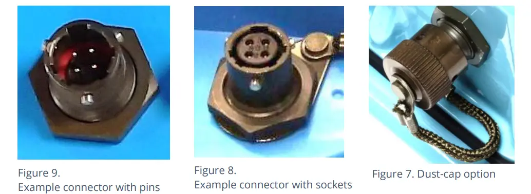
Wired connections are made to the logger via a connector mounted through the logger case. Various sizes are available and can contain either pins or sockets. Some examples are shown in Figure 9 and Figure 8. A dust-cap is available as an option to keep unused connectors free of water and debris (see Figure 7).
Some connectors are single-purpose in nature (e.g., For connection of a single sensor). However, other connectors may be multi-purpose (e.g., Having both a connection for a programming cable and also for the supply of power from an additional battery).
Where a connector is multi-purpose, a Y-adapter cable may be required to split out the various functions.
For water pressure measurement, the electrical connection to the sensor may be made via a standard electrical connector. This interface is known as an “External Pressure” type. It allows a cabled pressure transducer (sensor) to be connected to the logger. HWM can provide a variety of cabled pressure sensors with the appropriate connector for the logger.
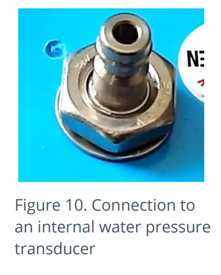
An alternative for water pressure measurement is for the transducer (sensor) to be built into the unit, as shown in Figure 10. This logger interface is known as an “Internal Pressure” type. It allows pressurized water to be connected to the logger directly, via the use of hoses fitted with a quick-release connector.
For antenna, a different type of connector is used. Refer to section 5.18.
The Multilog2 supports a variety of sensors and parameter measurements. Examples are given below: (Dependant on model number ordered).
- Pressure. Examples: – Direct connection to an internal transducer (referred to as an ‘internal’ pressure sensor). -Electrical connector for a wired transducer(referred to as an ‘external’ pressure sensor).
- Distance to a water surface Example: – By using a SonicSens2 sensor. -By using a SonicSens3 sensor.
- Water depth.Examples: – By using a SonicSens2 or SonicSens3 sensor. -By use of a submerged pressure gauge.
- Water leak detection (from pressurized water pipes).Examples: – By use of a HWM Leak-Noise Sensor or Hydrophone.•Water (or Gas) Consumption (Flow rate / total consumption).Examples: – Various ‘Flow’ channels are available to suit a variety meter pulse output formats.
- Temperature.Example: – By use of a PT100 temperature sensor.
- Status InputExample: – To detect an open/closed switch.
- Status Output. Examples: – Pulse replication of Status Inputs. -To activate some external equipment.
- GPS input (communication from Global Positioning System satellites). Examples: – To determine current time (high accuracy).-To determine current location / confirm still at installation site.
- 0-1V input.(or 01-10V)(This is a generic sensor interface.The logger supports inputs from externally powered sensors).
- 4-20mA input. (This is a generic sensor interface.
- MODBUS
- SDI-12The logger supports inputs from externally powered sensors Optionally, the logger can provide power to compatible sensors). (This is a widely used interface for sensor communications. The logger supports inputs from externally powered sensors. Optionally, the logger can provide power to compatible sensors). (This is a widely used interface for sensor communications. The logger supports inputs from externally powered sensors).
- (Others). Contact your sales rep for more information or to discuss your requirements.
For any given parameter, several sensors may be available with different types of electrical interface. Sensors provided by HWM will include a cable with a suitable connector for the supplied Multilog2.
INSTALLATION
SUMMARY OF INSTALLATION STEPS
- Check that an assessment of the work has been done and that any safety measures are in place. (E.g., Safety precautions, protective clothing and/or equipment being used).
- Check the logger is suitable for use at the installation site.
- Check that you have the required sensors and antenna.
- Consider where the equipment is going to be located within the available space and that all cables and any hoses are of a suitable length.
- Check fittings are available to connect to any pressure measurement point.
- The logger, cables, and sensors should be kept away from sources of electrical interference such as motors or pumps.
- Cables and hoses should be routed and secured so as to not cause any hazards. Do not allow any equipment to rest on cables, connectors, or hoses as crush damage can result.
- Select the appropriate programming cable for the logger and attach it to the logger COMMS connector. Complete the connection path to the IDT host device (see sections 2.7 and 2.8). Use IDT to read the logger settings. (Refer to the IDT user-guide for guidance whenever needed).
- Update the logger firmware (if required).
(Refer to the IDT manual for guidance; consider downloading any existing data from the logger prior to upgrade). - Use IDT to check or modify existing logger settings.
- Program a local time-zone into the logger (check or modify).
- Set timing intervals for making measurements (sample interval and log interval). They should be configured to suit your application’s specific logging requirements (minimise sampling rates to preserve battery life).
- Check / modify channel settings to produce measurement samples and the required datapoints from each interface.
- Configure the logger channel to match the sensor or other equipment that the logger connects to.
(Check units of measure are correct, etc) - Ensure the sensor is mapped to the correct output channel number; This is an identifier used when uploading the logged measurement data to the server. (i.e., Channel numbers must match between logger and DataGate).
(Note: For loggers using WITS protocol, requirements are different; refer to the guidance in the WITS supplement, MAN-147-0017). - Apply any required statistical functions to the background measurement samples in order to produce logged data-points (saved values).
- Where required, undertake the setup of any additional options related to the channel. (E.g., add an initial meter reading, pulse replication setting, sensor calibration; these will be dependent on sensor and logger use).
- For pressure sensors, electrically attach them but expose the sensor to the local atmospheric pressure and re-zero them (using IDT) before commencing making a connection to the measurement point.
- Install (position and connect) the sensors at their measurement point.
- Bleed any connections to water.
- Where required, insulate any water-filled tubing connected to pressure transducers to protect them from frost. (Insulating pipe covers can be supplied upon request at additional cost or sourced locally from a hardware store).
- Ensure any electrical connections made on site are dry, durable and water-tight.
- Use IDT to:
- Test the logger and sensors are functioning correctly. (Some can be done pre-installation; others post installation).
- Setup the logger for any alarms. Consider the conditions for activating alarm messages and also the conditions for the alarm to clear.
- Check / modify the communications settings of device, as required:
- SIM settings (parameters for giving access to the cellular network).
- Modem settings (cellular network technology).
- Data delivery settings (server contact details).
- Call-in times and protocol settings.
- Verify any changes to settings have been saved prior to leaving site. Check that the logger is in a “recording” state.
- Where the logger has a GPS antenna connection, install (position and connect) the GPS antenna for picking up the satellite communications.
- Use IDT to test the GPS installation is correctly working (GPS test).
- If used for obtaining a location fix, setup GPS location fix schedule and any GeoFence alarm requirements.
- Install (position and connect) the antenna for server communications.
- Use IDT to test the cellular communications performance.
- Ensure details of the site of logger deployment are recorded.
- (The administration for the server could be handled by office staff, or the installer could use the HWM Deployment app).
INSTALLING THE LOGGER
The logger must be mounted in a suitable location where the sensors to be attached can reach their intended installation points. Position loggers, sensors, and antenna away from sources of electrical interference such and motors or pumps. Cables and hoses should be routed without causing any hazards. Do not allow any equipment to rest on hoses, cables or connectors as crush damage can result.
The logger should be installed in the orientation shown in Figure 1 for optimum battery performance.
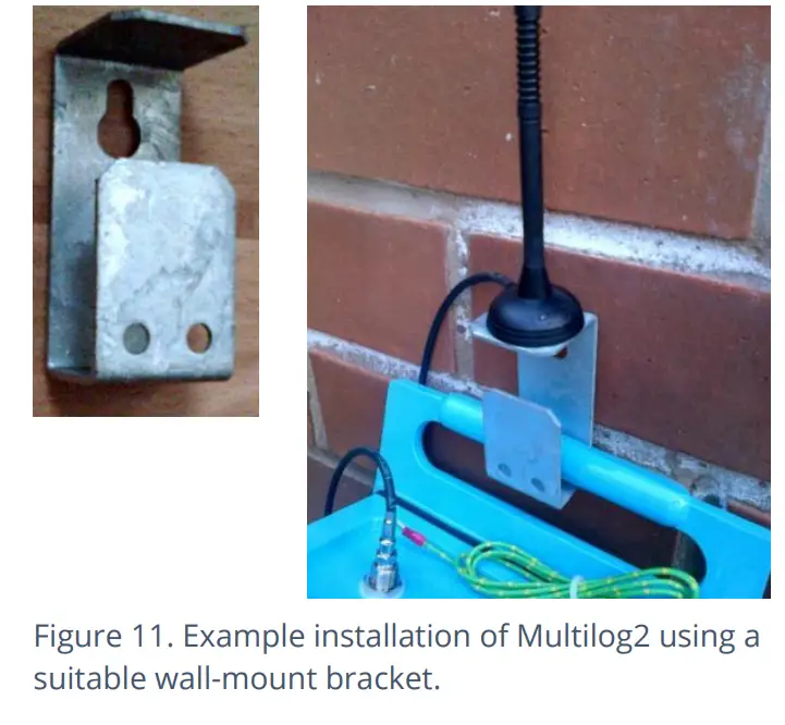
WALL-MOUNTING
The Multilog2 can be secured to a wall using a suitable bracket, an example of which is shown in Figure 11. Ensure the wall and fixings used are able to bear the weight of the logger and cables attached.
The bracket used may offer a potential mounting location for the antenna, although the installer should seek to find the optimal location for the antenna within the installation.
ELECTRICAL CONNECTIONS TO THE LOGGER
When making electrical connections to the logger (e.g., attaching a connector for a sensor), ensure the connector is correctly fitted. Both parts of the connector should be dry and free of debris. The connectors are keyed to ensure correct alignment of pins and receptacles. Align the sensor to the logger connector and push fully home. Then rotate the outer part of the sensor connector until it engages with the fastening mechanism and locks into place. The connector will then be secure and watertight.
When removing connections, follow the reverse steps of the procedure describe above. Always handle the connection by the connector; do not pull the cable as this could cause damage.
Route all cable so they do not cause any potential hazards and secure into place using suitable ties.
For antenna, follow the steps given in section 5.18.
FACTORY SETTINGS
Note: The logger will usually have settings pre-programmed by the factory prior to shipping. However, the installer has responsibility for confirming the settings are appropriate for use at the installed site.
If you have specific requirements this can be discussed with your HWM sales representative at the time of ordering the loggers.
Where required, IDT can be used to check or make any changes to the logger settings.
For most sensor interfaces, follow the general guidance within the IDT user-guide; the logger complies with the description and examples of setup provided therein. However, some HWM sensors require specialized setup screens or have their own user-guide which provides further guidance.
PRESSURE SENSOR INPUTS
RE-ZERO FACILITY (FOR PRESSURE RELATIVE TO LOCAL ATMOSPHERE)
Pressure sensors supplied by HWM normally measure pressure relative to atmospheric pressure. Since there can be some variation in local atmospheric pressure (e.g., due to altitude), the loggers have a facility to re-zero the pressure sensor.
This must be done with the sensor exposed to atmospheric air.
Prior to connecting the transducer to the actual measuring point, leave it exposed to air. Then “re-zero” the sensor using the method found in the IDT user-guide.
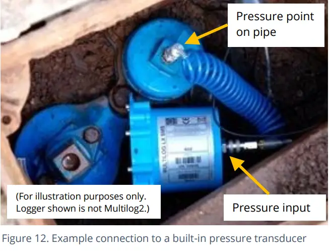
PRESSURE SENSOR (INTERNAL)
A pressure input may be presented as a built-in transducer (as shown in Figure 10, on page 14), which connects directly to the fluid via a hose using a quick-release connector.
Note: Do not connect the sensor to the measurement point before going through the re-zero (to local atmospheric pressure) process, if required.
Connect the pressure tapping on the pipe (measurement point) to the pressure transducer of the logger using a suitable interconnecting hose. (For an example, see Figure 12.) Ensure the hose is bled, for correct operation.
This interface is factory calibrated. No on-site calibration is required.
Note: Add insulation to the pipe and logger to prevent freezing.
If the water in the hose or the logger itself freezes, there is a danger of permanent damage to the pressure transducer.
PRESSURE SENSOR (EXTERNAL)
A pressure input may be presented as an electrical interface, using a 4-pin or 6-pin MIL-Spec connector (see Figure 9 on page 14).
Cabled pressure sensors for the Multilog2 are available from HWM. For most situations, sealed type pressure (or depth) sensors are used, and the sensor will be wired directly to the connector, as shown in Figure 13.
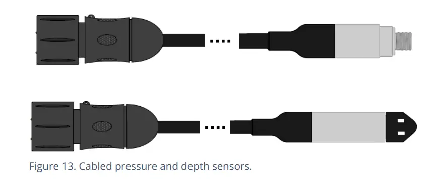
The logger temporarily applies power to the sensor just before (and during) making a measurement.
The logger interface will be labelled “Pressure (20 bar)” (or similar).
The pinout of the connectors are shown below.
| Logger bulkhead connector pinout : 4-pin External Pressure | |||
| A | B | C | D |
| V (+) ; (PWR) | V (+) ; (Signal) | V (-) ; (PWR) | V (-) ; (Signal) |
| Logger bulkhead connector pinout : 6-pin External Pressure | |||||
| A | B | C | D | E | F |
| V (+) ; (PWR) | V (+) ; (Signal) | V (-) ; (PWR) | V (-) ; (Signal) | GND / Screen | (not connected) |
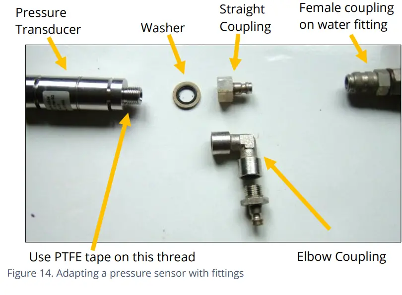
Where a pressure transducer has a threaded end for connection to the pressure measurement point, fittings may be required to modify the connection (e.g., a quick-release connector for connection to a hose). For example, see Figure 14.
Assemble any fittings prior to connecting to the logger.
Straight or elbow styles of coupling kits are available.
Confirm the logger has the appropriate interface for the pressure or depth sensor. Then connect the sensor to the relevant logger interface.
Note: Do not connect the sensor to the measurement point before going through the calibration process (see below) and then re-zero (to local atmospheric pressure).
For a pressure sensor, attach to the measurement point and (if applicable) bleed any connecting hose.
For a depth sensor, the sensor should be weighted down or mounted securely at the bottom of the water channel, using a fixture (e.g., a carrier plate or anchoring bracket) if required. The cable should also be secured in place to prevent moving water from acting on the cable to pull the sensor out of position or stress any connections.
Calibration Process (using calibration values from the cable):
Prior to using the sensor, the logger and sensor pair must be calibrated to give correct readings.
This method can be used by an installer to pair and calibrate a pressure sensor to the logger.
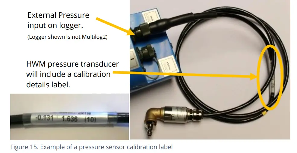
HWM supplied pressure / depth sensors usually have calibration values shown on the cable (see Figure 15). Use IDT to add the details from the calibration label on the cable into the logger using the guidance within the IDT user-guide.
The calibration process must occur before the re-zero of the pressure sensor.
After following the calibration process and re-zero process, the transducer can be located at (or fitted to) its measurement point.
The logger must be correctly set up to make measurements from the sensor. Refer to the IDT user-guide for further details.
Calibration Process (using applied pressures):
This method can be used by an authorized service center to pair and calibrate a pressure sensor to the logger.
The method consists of applying reference pressures to the transducer and building a table of calibration values.
FLOW SENSOR INPUT (METER PULSE COLLECTION)
Depending on the model supplied, the logger may have 0, to 6 Flow inputs. These are digital inputs, designed to sense the open or closed condition of a switch (activated by the installed meter). To use the flow channel(s) the logger must be set up (using IDT) to know what each meter pulse represents.
EXPLANATION OF FLOW CHANNELS & INPUT SIGNALS
Flow of a fluid in a pipe is usually detected by a meter, which produces pulses related to the volume of fluid passing through it. There are several types of meters; some can detect both forward flow and reverse flow (bi-directional flow); some can detect flow in one direction only (uni-directional flow). There are therefore several ways of implementing the meter pulse output signals from a meter. Your logger must have the correct interface and settings for the signaling from the meter to be compatible with it.
The Multilog2 Flow inputs sometimes require two input signals in order to work with the meter-pulse signaling of certain meters. A pair of inputs can therefore sometimes be configured to operate as a single channel. Other meter types only require one signal, so the pair of inputs can operate as two separate channels.
The pair of Flow signals can be labeled in one of the following ways:
| Alternative signal names | ||||
| Pair of FLOW
signals |
Flow Input 1 | Flow 1 | Pulses | Flow (Forward) |
| Flow Input 2 | Flow 2 | Direction | Flow (Reverse) | |
| Common | GND | |||
The labeling depends on the factory default for the configuration of the Flow channels on your logger model-number, but sometimes alternative types of configuration can be achieved by changing logger settings.
Where the logger is pre-configured by the factory to produce only 1 Flow channel (datapoint stream), the pair of inputs can be used in one of three different ways:
(1) Input 1 can be used with a Uni-directional meter (one which only measures forward flow / consumption).
For use in this configuration:
• Input 1 acts to collect meter pulses, and
input 2 is usually left disconnected (or allocated to use as a ‘Tamper Alarm’, or used as a Status input).
(2) Inputs 1 and 2 can be used as a pair with a Bi-directional meter (one which can measure both forward and also reverse flow).
For use in this configuration:
• Input 1 acts to collect meter pulses, and
• input 2 is used for the flow direction indication from the meter
(open = forward flow, closed = reverse flow).
(3) Inputs 1 and 2 can be used as a pair with a Bi-directional meter (one which can measure both forward and also reverse flow).
For use in this configuration:
• Input 1 acts to collect meter pulses (forward flow direction), and
• input 2 acts to collect meter pulses (reverse flow direction).
Where the logger is pre-configured by the factory to produce 2 Flow channels
(datapoint streams), the pair of inputs can be used as 2 independent uni-directional Flow input channels (channels 1 and 2).
Each input can be used with a Uni-directional meter (one which only measures forward flow / consumption).
VIA A LOGGER 4-PIN BULKHEAD CONNECTOR
Multilog2 Flow signal inputs are presented on a 4-pin connector (see Figure 9 on page 14). Each connector has a pair of Flow signal inputs.
The pinout of this connector is shown below:
| Logger bulkhead connector pinout : 4-pin Flow Inputs | ||||
| Pin | A | B | C | D |
| Signal | (not connected) | Flow Input 1 | Flow_GND | Flow Input 2 |
Check the meter to which the logger is going to be connected and ensure its meter pulse signaling method is understood, along with the significance of each meter pulse.
Connect the logger to the meter-pulse outputs of the meter using a suitable cable. If cables with bare tails have to be interconnected, refer to the guidance in section 5.5.
Use IDT to complete the setup, ensuring the logger is correctly set to interpret the meter pulses. If the logger is required to keep track of the meter counter display, take an initial reading of the meter counter and program it into the logger. The logger uploads additional consumption regularly, so a meter reading can be made remotely.
CONNECTING UNTERMINATED CABLE WIRES TO EQUIPMENT
When using a cable that is unterminated, an installer will be required to make their own connection to the other equipment on site.
When making a connection to Multilog2 you will normally need to splice the bare tails together. It is important that a waterproof connector housing is used, such as the “Tuff-Splice” enclosure available from HWM.
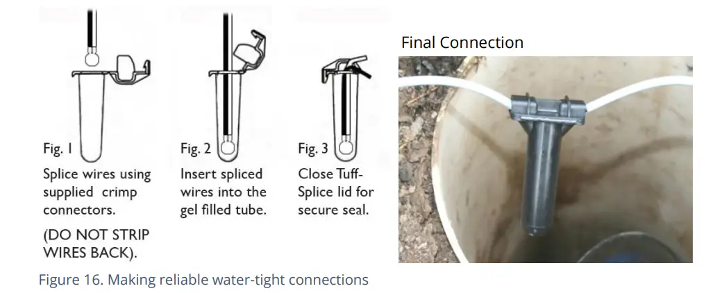
Note: Long data connections should always be made using screened cable. The use of screened cable will ensure maximum rejection of interference from outside sources. Always use a common ground point without creating ground loops.
STATUS INPUT
The Status Input pins are a re-purposed use of the Flow input electronics (see section 5.4). A change in the software driver for the connector gives the input pins a different functionality.
The interface will be labelled as ‘Status’ or ‘Dual Status’.
The pinout of this connector is shown below:
| Logger bulkhead connector pinout : 4-pin Status Inputs | ||||
| Pin | A | B | C | D |
| Signal | (not connected) | Status Input 1 | Status_GND | Status Input 2 |
The Status Input signals can be configured for general-purpose use in detecting switch contacts. This has many uses.
e. g.
- Detection of door / window / equipment-access openings for security purposes.
- A ‘spare’ pin on a flow channel can be used to generate a ‘tamper’ alarm in the event that the logger cable is cut or removed from the meter.
(The meter must support this facility by providing a closed loop from the tamper input to the return pin, Status_GND).
Connect the logger to the external equipment using a suitable cable. If cables with bare tails have to be interconnected, refer to the guidance in section 5.5.
Use IDT to complete the setup, ensuring the logger is set to generate the desired alarm.
OUTPUTS (DIGITAL SWITCH: OPEN/CLOSED)
Multilog2 Outputs are presented on a 3-pin connector (similar to Figure 8 on page 14). Up to four outputs can be supported. Each connector has a pair of outputs.
The interface will be labeled as ‘Dual Output’.
The pinout of this connector is shown below:
| Logger bulkhead connector pinout : 3-pin Outputs | |||
| Pin | A | B | C |
| Signal | Output 1 | Output 2 | GND |
The logger does not supply any power to the output. The output takes the form of an electronic switch (transistor), which can either be open or closed. When closed, the current path or is between the output pin and ground.
The maximum rated voltage is 12V (D.C.)
The maximum rated current is 120mA.
A common use of the Output pins is for pulse replication (of meter pulses that are input to the Flow channels). Where this is implemented:
- Flow input 1 is replicated to Output 1
- Flow input 2 is replicated to Output 2
- Flow input 3 is replicated to Output 3
- Flow input 4 is replicated to Output 4
The Output signals may also be used to activate external equipment.
In order to use the outputs, a suitable cable is required (the exact requirements will depend on the equipment the logger is being used with; discuss with your HWM representative). If cables with bare tails need to be interconnected, refer to the guidance in section 5.5.
Use IDT to complete the setup, depending on your application for the output.
EXTERNAL BATTERY
The use of an external battery is optional for many installations but may be required to support the logger in order to obtain the required length of service.
For best battery life, orient the external battery in its preferred orientation (refer to the labelling on the battery). Batteries are heavy devices. When positioning the battery, check that it is not crushing any cables or tubes within the installation. Ensure the battery is secure in its installation position (so it cannot fall). Then connect it to the logger.
The logger connection for an external battery will be presented via a (6-pin or 10 pin) connector that is shared with the programming interface (labelled “COMMS”).
The cable that is used for interconnecting the external battery pack to the logger will only include the pins required for supply of power; pins assigned for communications purposes will not be fitted.
The external battery connection must be temporarily disconnected whenever a logger programming cable needs to be attached.
SONICSENS 3 (ULTRASOUND DISTANCE / DEPTH SENSOR)
Where a SonicSens3 interface is available on your logger, it will have a 6-pin connector, similar to that shown in Figure 8, on page 14.
The interface provides power and communications to the sensor, which measures distance to a fluid surface. By input of other parameters (e.g., distance from the bottom of the water channel) the logger can calculate water depth. It can also derive a variety of other measurements such as flow rates if situated near an open weir.
Refer to the SonicSens-3 user-guide (MAN-153-0001) for instructions on how to install and setup the sensor for operation.
Note: Multilog2 loggers are not of an intrinsically safe construction, and so cannot be used within an environment where a potentially explosive atmosphere may be present.
SONICSENS 2 (ULTRASOUND DISTANCE / DEPTH SENSOR)
Where a SonicSens2 interface is available on your logger, it will have a 4-pin connector, as shown in Figure 8, on page 14.
The interface provides communications to the sensor, which measures distance to a fluid surface. By input of other parameters (e.g., distance from the bottom of the water channel) the logger can calculate water depth. It can also derive a variety of other measurements such as flow rates if situated near an open weir.
Refer to the SonicSens-2 user-guide (MAN-115-0004) for instructions on how to install and setup the sensor for operation.
Note: Multilog2 loggers are not of an intrinsically safe construction, and so cannot be used within an environment where a potentially explosive atmosphere may be present.
TEMPERATURE INPUT (RTD – PT100)
The logger may be constructed with a 4-pin connector (see Figure 9, on page14) for connection of a temperature sensor. Typically, this will be a PT100 RTD sensor. The logger interface will be labeled “TEMP” or similar).
The pinout of the connectors is shown below.
| Logger bulkhead connector pinout : 4-pin Temperature (RTD -PT100) | |||
| A | B | C | D |
| Temp_V + | Temp_S + | Temp_V – | Temp_S – |
| Logger bulkhead connector pinout : 6-pin Temperature (RTD -PT100) | |||||
| A | B | C | D | E | F |
| Temp_V + | Temp_S + | Temp_V – | Temp_S – | GND / Screen | (not connected) |
In order to use the temperature sensor, calibration of the input is required.
When ordered with a temperature sensor from HWM, the sensor will have the correct connector fitted for the Multilog2 logger. The logger input will also be factory calibrated for use with the supplied sensor.
LNS INPUT (LEAK-NOISE SENSOR / HYDROPHONE)
The logger may be constructed with a 4-pin connector (see Figure 9, on page14) for connection of a high sensitivity audio sensor, used for detecting the noise of a leak from a pressurized water pipe.
The interface will be labeled ‘LNS INPUT’ (or similar).
Typically, the sensor will be a Leak Noise Sensor from one of the HWM PR4LNS-1 family. The Multilog2 is also compatible with the Hydrophone-2 sensor (and its earlier version, Hydrophone). Both use the same connector. There are only minor differences in setup of the logger for their use. There are significant differences in their installation methods.
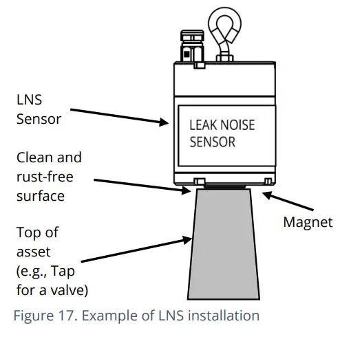
Installation of the magnetic type LNS sensor:
The logger uses the sensor to listen to sounds produced from the pipe network. It then uses special algorithms to judge whether a leak is likely to be present nearby.
The audio sensor within the LNS unit is attached to the outside of the pipe network for use, usually using a magnet to attach it to a metal pipe asset (hydrant or valve) within a chamber. Refer to Figure 17.
The sensor should ideally be attached to an upper surface of the asset, with the sensor facing downwards. (This reduces the risk of the sensor falling).
Prior to installing the sensor, clean the asset attachment point and remove any rust from it, using a wire brush; this ensures a good contact will be made with the pipe (for conducting sound).
Then connect the sensor cable to the logger.
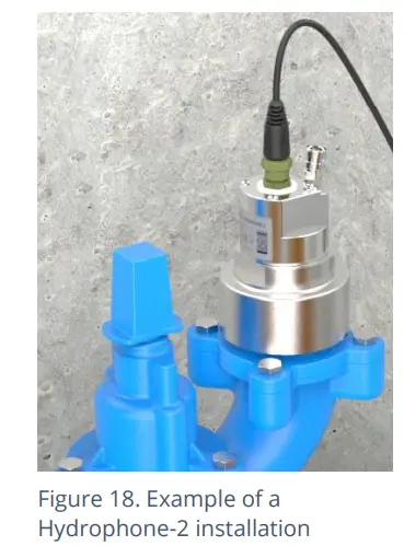
Installation of the Hydrophone-2 sensor:
The audio sensor within the Hydrophone-2 unit connects directly to the water inside the pipe via an access point, such as a hydrant (see Figure 18). This gives it a longer range of operation than the LNS, especially in plastic pipes.
Installing the unit into the water network can be a dangerous operation unless carried out correctly. Refer to the Hydrophone-2 user-guide
(MAN-165-0001) for installation and use details.
Behaviour of Logger and Server:
The use of a Leak-Noise sensor or Hydrophone can cause some changes (additions) to the logger’s pattern of behavior. This section provides a summary of the loggers use of the sensors; For a detailed explanation, refer to the PermaNet+ with Hydrophone-2 user-guide (MAN-148-0007).
The output from the logger will include a variety of parameters, each of which will be a datapoint channel.
The leak detection parameters will include:
- Level
- Spread
- Leak / No-leak judgment
For most water network installations, the logger will typically run an extensive leak test cycle once a day. However, when used to monitor critical parts of the water network, such as trunk main, an alternative test cycle is available (called ‘Trunk Main’ mode); This runs a shorter noise evaluation test much more frequently, in order to provide an earlier indication of potential leak issues.
In addition to the leak detection parameters, the logger can produce other types of supplementary data, such as sound recordings (audio files). These are also uploaded to the server and can be listened to remotely by an experienced user, to make a judgement on whether the sound is similar to that of a water leak.
If the logger can find a highly accurate time reference from where it is installed
(e.g., from the cellular communications network or a GPS satellite), a high-accuracy time-stamp will be linked to the audio file.
The server may provide the facility to group several loggers (local to each other) that are reporting a leak and then check for sound recordings. Providing the audio recordings were made at exactly the same time, the server can use them to try to locate the position of the potential leak on the pipe network.
Other data that can be obtained from the logger are noise histograms (to evaluate if a change has occurred in the pipe noise characteristics recently).
ANALOGUE VOLTAGE INPUT (0-1V, 0-10V)
The logger may be constructed with a 4-pin connector (see Figure 8, on page 14) for connection of a sensor which employs an output voltage level as a method of signalling. Both a 0-1V and a 0-10V input interfaces are available on Multilog2 but must be specified at the time of ordering.
The logger does not provide power to the sensor; it must have its own source of power.
The pinout of this connector is shown below:
| Logger bulkhead connector pinout : Voltage Input 0-1V (& 0-10V) | ||||
| Pin | A | B | C | D |
| Signal | (not connected) | 0-10V + /
0-1V + |
(not connected) | 0-10V – /
0-1V – |
A wide variety of sensors are available with this interface.
When ordered from HWM, the sensor will have the correct connector fitted for the Multilog2 logger.
The installer will have to use IDT to confirm or adjust the settings of the logger to correctly scale and interpret the physical parameters the attached sensor is used to detect.
ANALOGUE CURRENT INPUT (4-20MA)
The logger may be constructed with a 4-pin connector (see Figure 8, on page 14) for connection of a sensor which employs an output current as a method of signalling.
Two interface types are available:
- Passive.
- Active.
4-20MA (PASSIVE)
Where a ‘passive’ 4-20mA interface is fitted, the logger does not provide power to the sensor; it must have its own source of power.
The logger interface will be labelled “4-20mA” (or similar).
The pinout of this connector is shown below:
| Logger bulkhead connector pinout : Current Input (4-20mA) | |||
| A | B | C | D |
| (not connected) | 4-20mA + | (not connected) | 4-20mA – |
A wide variety of sensors are available with this interface.
When ordered from HWM, the sensor will have the correct connector fitted for the Multilog2 logger.
The installer will have to use IDT to confirm or adjust the settings of the logger to correctly scale and interpret the physical parameters the sensor is used to detect.
4-20MA (ACTIVE)
Where an ‘active’ 4-20mA interface is fitted, the logger can provide power to a compatible sensor.
The logger interface will be labelled “4-20mA (Active)” (or similar).
The pinout of this connector is shown below:
| Logger bulkhead connector pinout : Current Input (4-20mA) | |||
| A | B | C | D |
| V+ (PWR) | 4-20mA + | GND (PWR) | 4-20mA – |
A wide variety of sensors are available with this interface. However, not all have the same power requirements. The connector is able supply up to 50mA of current. The output voltage is variable (from 6.8 V to 24.2 V, in 32 steps), and is able to be set using IDT.
To avoid damage: Prior to connecting the sensor, use IDT to ensure the correct output voltage for the sensor is set.
The logger does not supply continuous power to the interface, but only activates it for a short time whilst making a measurement. IDT gives access to controls to set the amount of time the sensor has power applied prior to and during measurement. The installer can set these to allow for any initialisation or settling time the sensor requires.
When ordered from HWM, the sensor will have the correct connector fitted for the Multilog2 logger.
The installer will have to use IDT to confirm or adjust the settings of the logger to correctly scale and interpret the physical parameters the sensor is used to detect.
The interface can also be used with sensors having their own source of power.
SERIAL INPUT (SDI-12)
The logger may be constructed with a 4-pin connector (see Figure 8, on page 14) for connection to equipment which employs the SDI-12 method of signalling; this is a serial data interface. The external equipment drives any sensor electronics; one or multiple sensors may be attached to it.
The logger does not provide power to the SDI-12 interface. The attached equipment / sensor must have its own source of power.
The logger interface will be labelled “SDI-12” (or similar).
The pinout of the connector is shown below:
| Logger bulkhead connector pinout : SDI-12 | |||
| A | B | C | D |
| SDI-12_Data | (RS485,
Unused) |
Comms_GND | (RS485,
Unused) |
A wide variety of sensors are available with this interface.
When ordered from HWM, the sensor will have the correct connector fitted for the Multilog2 logger.
Note: Ensure the attached sensor has the SDI-12 protocol selected, otherwise communications will fail.
Using the SDI-12 protocol, the logger can make a request for a measurement to the attached equipment. The attached equipment responds when the measurement has been obtained.
The sensor equipment will have an address that the logger must use when communicating with it. Obtaining data begins by the logger requesting a measurement (sending an “M” command or a “C” command).
Some sensor equipment will send multiple items of measurement data as a block
(e.g., one piece of equipment may include several sensors). The setup of the logger can include an index to select the required data from the block.
The installer will have to use IDT to confirm or adjust the settings of the logger to request the required measurement data from the sensor. Setup of the logger should include the relevant addresses, commands, and indexes that are required to start the measurement and then select the specific data item required.
The installer is required to correctly scale and interpret the physical parameters the sensor is used to detect.
SERIAL INPUT (RS485 / MODBUS)
The logger may be constructed with a 4-pin connector (see Figure 8, on page 14) for connection of a sensor which employs the RS-485/MODBUS method of signalling; this is a serial data interface.
Note: Ensure the attached sensor has the RS485/MODBUS protocol selected, otherwise
communications will fail.
Two types of MODBUS interface are available:
- Passive.
- Active.
For a Passive interface, the logger does not provide power to the sensor; it must have its own source of power.
For an Active interface, the logger provides temporary power to the sensor, just before (and during) the measurement cycle.
The port type (active or passive) can be determined by inspection as to whether (or not) there is a voltage output control shown within IDT. In addition, the connector label will indicate ‘MODBUS’ or ‘POWERED MODBUS’.
A wide variety of sensors are available with this interface. When ordered from HWM, the sensor will have the correct connector fitted for the Multilog2 logger. In addition, the sensor type will have been tested with the logger to confirm compatibilty for use to obtain certain measurements. However, this may require selecting a specific driver for the sensor within IDT.
The Multilog2 operates as the master device when using the Modbus protocol. It sends setup instructions and other information to the attached sensor equipment (which operates in slave mode). The protocol includes the ability to address each register in order to read and (depending on the attached unit) write to the registers. Measurement results are made available to the logger by reading them from specific registers in the sensor equipment over the Modbus link.
The sensor equipment will have an address that the logger must use to identify it when communicating. The setup of the logger should therefore include the sensor address as well as the register access details (function code, start register address).
The quantity of registers to be read will depend on the format of the data within the sensor registers. The logger can handle multiple formats of numeric data (e.g., 16-bit signed, 16-bit unsigned, float, double); however, the expected data format must be specified in the logger setup; this will ensure that the required number of registers are read and that the data is correctly interpreted by the logger. The read data can then be used to obtain the channel datapoints.
When setting the logger for use with your sensor, usually the “generic” settings are suitable. However, some modification of the logger operation is required for certain types of sensor equipment in order to get the best out of them. IDT provides a control to select specific sensors from a list. Once chosen, the logger will handle any peculiarities of the behavior of the sensor, its protocol, or additional needs for the measurement being taken (e.g., additional exchanges of information between the logger and the sensor equipment).
Refer to the IDT user-guide regarding how to set up the RS485 / Modbus interface. This must be read in conjunction with the user-guide of the equipment that is being attached; this will provide information on the measurements available from the sensor equipment registers (and the numeric format of the data), and how to initiate register reads to obtain the required data.
The installer should use IDT to confirm or adjust the settings of the logger that request the required measurement data from the sensor. Then use IDT to correctly scale and interpret the physical parameters the sensor is used to detect.
RS485 / MODBUS (PASSIVE)
The logger interface will be labeled “MODBUS” (or similar).
The pinout of this connector is shown below:
| Logger bulkhead connector pinout : RS485 / MODBUS (passive) | |||
| A | B | C | D |
| (SDI-12,
Unused) |
RS485_A | Comms_GND | RS485_B |
A wide variety of sensors are available with this interface.
When ordered from HWM, the sensor will have the correct connector fitted for the Multilog2 logger. In addition, the sensor type will have been tested with the logger to confirm compatibilty for use to obtain certain measurements. However, this may require selecting a specific driver for the sensor wihin IDT.
The installer should use IDT to confirm or adjust the settings of the logger to request the required measurement data from the sensor. Then use IDT to correctly scale and interpret the physical parameters the sensor is used to detect.
RS485 / MODBUS (ACTIVE)
The logger interface will be labeled “POWERED MODBUS” (or similar).
Note: When supplied with (and configured for) a known sensor, the logger MODBUS interface may alternatively be labeled so as to identify the sensor itself. Examples are:
- Raven Eye
The pinout of this connector is shown below:
| Logger bulkhead connector pinout : RS485 / MODBUS (active) | |||
| A | B | C | D |
| V+ (PWR) | RS485_A | GND | RS485_B |
For an ‘Active’ interface, the logger usually provides temporary power to the sensor, just before (and during) the measurement cycle. The sensor used must be compatible with the logger power supply to the interface (voltage and current output). It also has to be compatible with the timing of the power activation and any exchange of messages. Consult your HWM representative for advice on sensor compatibility or if you have any specific sensor requirements.
A wide variety of sensors are available with this interface. However, not all have the same power requirements.
To avoid damage, check the sensor is compatible with the logger power supply range and use IDT to check that the logger power settings have already been correctly set prior to connection.
- The interface is able supply up to 50mA of current.
- The output voltage can be set using IDT (from 6.8 V to 24.2 V, in 32 steps).
IDT gives access to controls to set the amount of time the sensor has power applied prior to and during measurement. The installer can set these to allow for any initialization or settling time the sensor requires.
When ordered from HWM, the sensor will have the correct connector fitted for the Multilog2 logger. In addition, the sensor type will have been tested with the logger to confirm compatibility for use to obtain certain measurements. However, this may require selecting a specific driver for the sensor within IDT.
The installer should use IDT to confirm or adjust the settings of the logger to request the required measurement data from the sensor. Then use IDT to correctly scale and interpret the physical parameters the sensor is used to detect.
ANTENNA INPUT (GPS SATELLITE)
The Multilog2 may have been fitted with an internal radio receiver which can receive signals from GPS satellite stations. These loggers will have an additional antenna connector fitted, which must be connected to a GPS antenna for correct operation.
Note: Do not confuse this with the antenna supplied for cellular communication, as they are not compatible with each other.
The GPS antenna can be identified by the “GPS” indication on its cable, as shown in Figure 19.
An example of a ‘puck’ type GPS antenna is shown.
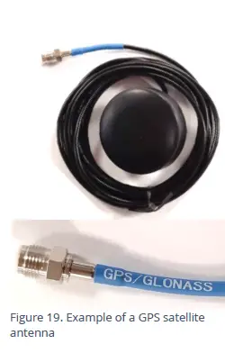
The connector will be labeled as ‘GPS TSYNC’ or ‘GPS CONNECTOR’ (or similar).
The antenna must be installed above ground and with a direct line of sight to the sky (to pick up the radio signals from orbiting satellites).
Example locations are:
- Surface mounted to a cabinet or post, pointing upwards.
- Embedded into the upper face of a suitably machined chamber lid, again pointing upwards.
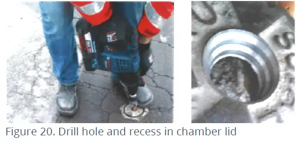
When fitting the antenna to a chamber lid, the lid is required to have a recess drilled out to accommodate the body of the antenna. The recess should be deep enough to protect the antenna from damage. An example of the required steps follows, for guidance:
- Check the dimensions of the supplied antenna and the thickness of the chamber lid. Consider how the antenna will be mounted in the lid. If the lid is insufficiently thick, a plate may be required to be fitted to the rear of the lid to increase the depth.
- Drill through the lid to make a path for the cable and connector to pass through.
- Drill partially into the lid using a wider drill to make a suitable countersink or recess that the body of the antenna can fit into.
 Thread antenna cable through hole, washer, and nut.
- Secure antenna to the lid using a washer and the supplied nut.
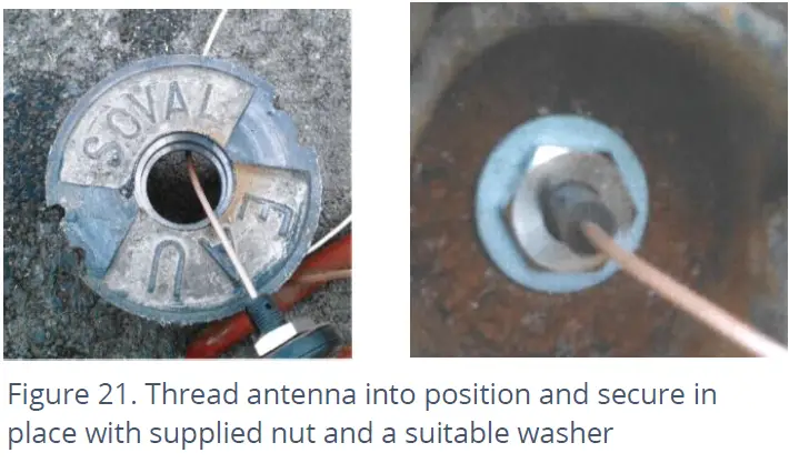
- If required, apply a resin epoxy such as Marine “Goop” to the perimeter of the antenna to help stabilize its position within the lid and to prevent water running onto the antenna cable. Do not cover the top of the antenna body as this may impair reception of satellite signals. Ensure all surfaces are clean and dry before applying the adhesive. Follow the adhesive manufacturer’s instructions.
- Ensure the antenna cable does not become damaged (e.g., by the lid) during installation and use.
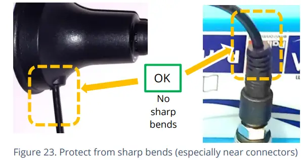
Connect the GPS Antenna to the GPS antenna connector on the logger. Do not over-tighten. For a reliable connection, apply silicon grease and O-ring to the connector prior to fitting, as detailed in section 5.18. Ensure there are no sharp bends in the antenna cable.
Prior to leaving site, use IDT to make a GPS test to confirm the antenna location is OK and that the satellite signals are being received.
ANTENNA (CELLULAR COMMUNICATIONS)
An antenna should be selected to suit the available space in the chamber, allowing some space for it to be re-positioned (if required). Only use HWM-provided antenna with your logger, to ensure the radio interface meets approvals requirements (safety, etc). The Multilog 2 logger uses a metal “FME” style antenna connector.
Prior to connecting the antenna, ensure that the connector is dry and clear of dirt and debris; trapped moisture or contaminants can impair the antenna performance. Clean if necessary.
Apply SG M494 silicon grease to the connector as required.
The antenna connector has an O-ring included for protection against water and moisture ingress; it acts as a seal. Check that the O-ring is present and undamaged.
Ensure that the connector and O-ring are dry and clear of dirt and debris. Clean carefully if necessary.
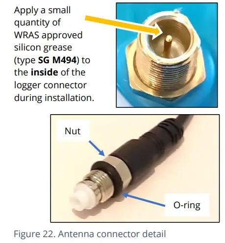
Insert the antenna connector into the logger connection and ensure it is fully home. Tighten the connector correctly; the nut on the antenna should be finger tight, plus 1/4 turn.
No sharp bends should exist at the cable ends, or in the routing of the antenna cable.
To avoid risk of crush damage to the antenna cable, check that no equipment is placed onto it. Similarly, cable ties fixing the cable in place should not be too tight.
The antenna should not be bent to fit the installation; if it is too big for the chamber, use a smaller type of HWM approved antenna.
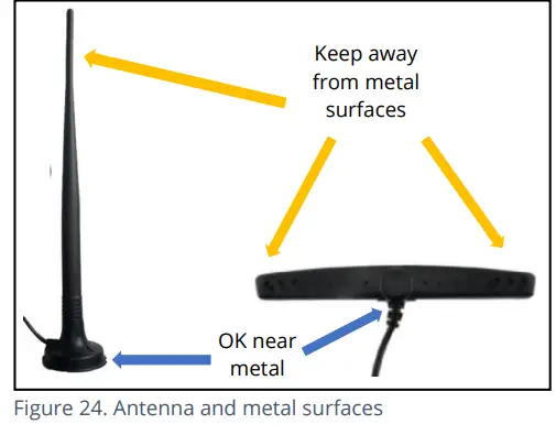
When positioning the antenna, ensure that the radiating end of the antenna does not touch or go close to a metal surface.
The radiating element of the antenna should ideally be positioned in free air (free from obstructions).
Try to avoid placing the antenna in a location where it can be flooded. If this is unavoidable, then place it where the risk is at its minimum.
For equipment that is installed in a chamber below ground level, the antenna should be placed above ground level if possible. Where this is not possible, position it near to the top of the chamber.
IDT should be used to check that the logger can connect to the cellular network and that the antenna is in the optimal position for the site.
- Choose a suitable antenna for the installation and decide on its initial position.
- Determine the network technology being used and then use the appropriate signal quality limits (refer to the IDT user-guide).
- Perform Network Signal tests (with the chamber lid closed) to confirm the logger connects to the mobile network and find the best location of the antenna. Re-position if required.
- Perform test calls to confirm the logger can communicate with the DataGate server via the internet and (if required / available) SMS.
(Details of use of IDT for making these tests are provided in the IDT app user-guide).
Trouble-shoot a test-call failure if required, using the advice in the IDT app user-guide. Further information is given in the HWM Antenna Installation Guide (MAN-072-0001).
Some general advice is given below:
Monopole Antenna
For most installations, a monopole antenna will give acceptable performance. Installation Considerations:
- Always comply with any installation restrictions as per warnings in the documentation supplied.
- The antenna has a magnetic base to be used for mounting.
For optimum performance, the antenna requires a “ground plane” (metal surface) at its base. - When installing the antenna in large underground chambers it should be positioned close to the surface.
- Ensure that any chamber lid will not interfere with the antenna or cables when being opened/closed.
- This antenna is vertically polarized, it should always be installed in the vertical orientation.
- Never bend the radiating element of the antenna.
- The antenna can also be attached to an installation bracket mounted to an existing marker post.
- Where an antenna is held in place by magnets, ensure the weight of any cables does not excessively load the magnet so as to detach it from the installed location.
- Do not allow any equipment to rest on the antenna connector as crush damage to the connector or antenna cable can result.

For other antenna options and additional installation guidelines, refer to the documents available on the support webpage: https://www.hwmglobal.com/antennas-support/
Troubleshooting a Call Test failure
There are a number of reasons why a Call test may fail.
The following points should be checked before calling HWM support for assistance:
| Possible Problem | Solution |
| Network Busy due to excessive traffic. Commonly occurs around schools and at peak travel times. | Retry the test after a few minutes. |
| Network signal not available at your location. Not all Cell masts carry data traffic | Relocate the logger to an area that has a data service or change to a different
network provider. |
| Network signal not strong enough.
For 2G and 3G networks, you need a CSQ (reported by the Call test) of at least 8 for reliable communications. For 4G networks, check the RSRP and RSRQ values are suitable, as described in the IDT user guide. |
Relocate the antenna if possible or try alternative antenna configurations. |
| APN settings incorrect. | Check with your network operator that you have the correct settings for your SIM. |
If you continue to experience problems with communication, you may need to check the network coverage in your location.
TROUBLESHOOTING
Any issues should consider all parts of the system (IDT, the user, the logger, sensors, the cellular network, and the server).
General checks:
Initial checks to be made during a site visit include:
- Check if the version of IDT you are using (IDT app for mobile devices / IDT for Windows PC) supports the features and sensors you are using; refer to section 8.
- Check that the latest version of IDT is being used.
- Check that the logger being used has the latest software (IDT will offer to upgrade if required).
- Check the battery voltage of logger is good (using the IDT Hardware Test).
- Check the cable and connectors between sensors and the logger are in an OK condition, with no damage or water ingress.
The logger does not appear to be able to communicate with IDT:
- Check the communications path from the IDT host device to the logger is complete.(See section 2.8.)
- If using the direct cable connection method with IDT (PC), the logger may have shut down the connection to IDT due to is not being used for several minutes. Re-read the logger settings into IDT. Any previously unsaved settings will have been lost.
- If using the IDT app, the permission to use the cable may have expired. Detach the USB-A end of the programming cable and re-attach a few seconds later. Give permission to use the cable and then re-read the logger settings into IDT. Any previously unsaved settings will have been lost.
The data from the logger does not appear on the server:
- Check the settings for the SIM card to access the mobile data network.
- Ensure the logger uses the correct data destination URL and port-number for your server.
- Check call-in times have been set.
- Check antenna is attached and in an OK condition.
- Check signal quality and strength parameters are suitable. Re-locate the antenna, if required, or try an alternative type of antenna.
- Make a Call Test and confirm OK.
- Ensure your server is correctly configured to receive and present the data.
MAINTENANCE, SERVICE AND REPAIR
Unauthorized servicing will void the warranty and any potential liability for
HWM-Water Ltd.
CLEANING
Note the safety warnings that are applicable to cleaning. The unit may be cleaned using a mild cleaning solution and a damp soft cloth. Always keep connectors free of dirt and moisture.
REPLACEABLE PARTS
Antenna
Only use antenna recommended and provided by HWM.
For details of antenna options and part-numbers to order, refer to the following link: https://www.hwmglobal.com/antennas-support/ (or consult your HWM representative).
Batteries
- Only use batteries and parts recommended and provided by HWM.
- Batteries are only replaceable by a HWM approved service centre or relevantly trained technician. Contact your HWM representative for more details if required.
- Batteries can be returned to HWM for disposal. To arrange the return, complete the on-line RMA (Returned Materials Authorisation) form: https://www.hwmglobal.com/hwm-rma/
- Refer to the Safety Warnings and Approvals Information for guidelines of the packing requirements.
SIM-card
- SIM-cards are replaceable by a HWM approved service center or relevantly trained technician.
- Only use consumable parts recommended and provided by HWM.
RETURN OF PRODUCT FOR SERVICE OR REPAIR
When returning product for investigation or repair, be sure to follow the instructions of your distributor to document why the product is being returned and provide contact details.
If returning to HWM, this can be done by completing the on-line RMA form: https://www.hwmglobal.com/hwm-rma/
Prior to shipping, put the equipment into Shipping mode (refer to the IDT user-guide for instructions). Refer to the Safety Warnings and Approvals Information for guidelines of the packing requirements.
If soiled, ensure the unit is cleaned with a mild cleaning solution and soft brush, disinfected, and dried prior to shipment.
APPENDIX 1: SYSTEMS AND FEATURES REQUIRING IDT (PC)
Historically, setup of Multilog2 loggers was undertaken using the IDT (PC/Windows) tool. Setup of most Multilog2 logger functions for Pressure and Flow channels and the most commonly used alarm types has recently been introduced to the IDT (mobile app) tool. However, the IDT (mobile app) does not yet support some situations.
The following logger types require IDT (PC) for their entire setup:
- WL/*/*/* Multilog2 logger device (models for use in WITS systems). Refer to the IDT (PC) user-guide for most settings. Additional information for WL series models can be found in the following user-guide: MAN-147-0017 (Supplement for models supporting WITS protocol).
- RDL6*LF/* Multilog (original) logger devices.
The following logger/sensor combinations require IDT (PC) for setup:
- Multilog2 using a SonicSens2 sensor.
- Multilog2 using a SonicSens3 sensor.
- Multilog2 using a RS485/MODBUS sensor.
- Multilog2 using an SDI-12 sensor.
- Multilog2 using a Hydrophone or LNS (Leak-Noise Sensor).
- Multilog2 using a GPS Satellite (for either location or Time-sync).
The following logger features require IDT (PC) for setup:
- Update of firmware of logger or attached sensors.
- Fast logging features (Pressure Transient, Enhanced Network logging).
- Flow Rate (when calculated from flow velocity, channel depth, channel geometry).
- Profile Alarm.
- Tamper Alarm.
- GPS functions, including GeoFence Alarm.
APPENDIX 2: COMMUNICATING TO LOGGER VIA SMS
Note: This facility may not be available on your logger, depending on the SIM card fitted. Some SIM cards or networks or service providers do not have SMS messaging available. (See also section 1.4).
- Applying a ‘Modem Activation Key’ (See Figure 25) to the 10-pin Comms interface for a period of 10 seconds will activate the logger’s cellular communications modem for a period of 5 minutes. This will allow an installer to send SMS (text) messages from a mobile phone and for the logger to respond.
(There is an alternative way to do this using IDT). - Close the chamber or cabinet such that everything is in its final position.
- Using a standard mobile phone, send a text message to the SMS number of the logger (check the logger label), including the international dialing code if needed.
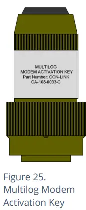
- The text message should read TTTT#
After a few seconds/minutes (depending on the network operator) the logger will send a message back to you with details of its current status.
- Example response from a logger:
TTTT138-002 V01.70CSQ:1010.9VyouridRT hh:mm ss dd-mm-yy …
To decipher the message returned, please refer to the table below:
| Message | Description |
| TTTT | Original command text without # |
| 138-002 | Logger type number |
| V01.00 | Firmware version in Logger. |
| CSQ: nn | Signal strength nn (nn = 6 to 30) |
| 10.9V | Operating voltage |
| yourid | Your Logger ID |
| RT hh:mm ss dd-mm-yy | Real Time Clock setting |
| ST hh:mm ss dd-mm-yy | First Time the logger was started |
| LR hh:mm ss dd-mm-yy | Last Time the logger was re-started |
| Ch1 (A) 0029.0 | Channel 1 29.0 units |
| Ch2 (A) 0002.2 | Channel 2 2.2 pulses/sec |
If the CSQ: value in the message is OK, then the installation is complete. The logger will automatically go back to sleep after 10 minutes.
There can be delays in the SMS network, so the response to your message may not be immediate. If you have had no response in 10 minutes, re-open the chamber and using the modem diagnostic send yourself a test SMS. If this gets through, then improve the location of the antenna and try again.
Note: Some Roaming SIM cards do not accept incoming text messages.
Check with your service provider if you are unsure.
- Fluid Conservation Systems 1960 Old Gatesburg Road Suite 150
- State College PA, 16803 800-531-5465
- www.fluidconservation.com
FAQ
Q: Where can I find additional support for Multilog 2?
A: For further assistance not covered in the manual, contact the HWM Technical Support team at +44 (0) 1633 489479 or email cservice@hwm-water.com.
Documents / Resources
 |
FCS Multilog2 Multi Channel Data Logger [pdf] User Manual ML- - -, PT- - -, EL- - -, Multilog2 Multi Channel Data Logger, Multilog2, Multi Channel Data Logger, Data Logger, Logger |