FCS Multilog2 Multi Channel Data Logger
Specificazioni
- Nome di u produttu: Multilog 2
- Tipu di dispusitivu: Data Logger
- Modelli coperti: ML/*/*/* PT/*/*/* EL/*/*/* WL/*/*/*
- Modelli supplementari: WL series models for WITS systems
- Software Tool: IDT (Installation and Diagnostic Tool)
INTRODUZIONE
The “Multilog2” is a multi-purpose data logger device. Several models are available. Please contact your sales representative for help with selection of an appropriate model for your application.
HWM also provides a software tool, known as “IDT” (“Installation and Diagnostic Tool”) for logger setup and test. (See also section 1.6).
MODELS COVERED, DOCUMENTATION AND SUPPORT OF PRODUCT
Questa guida d'utilizatore copre i seguenti mudelli:
Numeru di mudellu Descrizzione di u dispusitivu
| Numero di mudellu | Descrizzione di u dispusitivu |
| ML/*/*/* | Multilog2 logger device. |
| PT/*/*/* | Pressure Transient2 logger device. |
| EL/*/*/* | Enhanced Network2 logger device. |
| WL/*/*/* | Multilog2 logger device (models for use in WITS systems).
– Additional information for WL series models can be found in the supplementary user guide. |
Questa guida d'utilizatore deve esse lettu in cunghjunzione cù:
| Numero di documentu | Document Description
Safety Warnings and Approvals Information (for Multilog2). Guida di l'utente IDT (versione PC). Multilog2 (Supplement for models supporting WITS protocol) IDT (app for mobile devices) user-guide. |
| MAN-147-0003 | |
| MAN-130-0017 | |
| MAN-147-0017 | |
| MAN-2000-0001 |
Questa guida d'utilizatore furnisce dettagli di l'operazione di logger è cumu installà u pruduttu. Riferite ancu à qualsiasi guida d'utilizatore o datasheets per i sensori chì sò stati utilizati cù u logger.
Leghjite e parte pertinenti di a guida di l'utente IDT per una guida nantu à cumu cunfirmà i paràmetri o mudificà a cunfigurazione di u vostru logger. Questu include:
- Detaglii di a cunfigurazione di i canali di sensori è a registrazione di e dati.
- Configurazione di logger per a consegna di dati di misurazione à un servitore.
- Configurazione di Logger per funzioni di messageria supplementari, cum'è alarmi.
Nota: U sistema hà periodicamente nuove funzionalità è cambiamenti publicati, dunque pudete osservà lievi cambiamenti da i diagrammi è e funzionalità mostrate in questu manuale. E funzionalità installate ponu varià da un dispositivu à l'altru, dunque riferitevi sempre à i menu è à e schermate di qualsiasi strumentu di cunfigurazione per determinà quali funzionalità sò dispunibili nantu à u vostru dispositivu logger.
HWM furnisce assistenza per i dispositivi logger per mezu di u nostru supportu à i clienti. webpagine: https://www.hwmglobal.com/help-and-downloads/
Sì avete qualchissia dumande chì ùn sò micca cuparti da stu manuale o aiutu in linea, per piacè cuntattate u squadra di Supportu Tecnicu HWM à +44 (0) 1633 489479, o email. cservice@hwm-water.com
CONSIDERAZIONI DI SICUREZZA
Prima di cuntinuà, leghjite attentamente è seguitate l'infurmazioni in u documentu "Avvertimenti di Sicurezza è Informazioni d'Omologazione" furnitu cù u pruduttu. Questu furnisce informazioni generali di sicurezza.
Mantene tutti i documenti per riferimentu futuru.
Before using this product, make a risk assessment of the installation site and expected work activity. Ensure suitable protective clothing is worn and working practises are followed during installation and any maintenance.
ATTENZIONE: Quandu stu equipamentu hè adupratu, installatu, aghjustatu, o servitu, questu deve esse fattu da un persunale qualificatu adattatu familiarizatu cù a custruzzione è u funziunamentu di l'equipaggiu è i periculi di qualsiasi rete di utilità.
TEMPERATURE DI FUNZIONAMENTO
Riferite à a Scheda di dati di logger o à u vostru rappresentante di vendita per una guida nantu à a gamma di temperatura di almacenamento è di operazione di u dispusitivu. Assurez-vous que l'unité se trouve à l'intérieur de la plage de températures de fonctionnement avant l'installation ou l'installation.
USE OF CELLULAR NETWORKS – IMPORTANT NOTES
Disponibilità di SMS
Most Multilog2 models include the ability to communicate to a server via use of the cellular data network. This is usually via the regular data network (which gives internet access). Alternatively, the SMS (Short Message Service) messaging can be used; in most cases this will be as a fall-back if the logger is temporarily unable to access the regular data network. If configured for SMS use, the logger uses the available 2G network.
Impurtante: I servizii 2G (GPRS), chì portanu u sistema di messageria SMS, sò pianu pianu disattivati in u mondu sanu. Una volta chì u 2G hè disattivatu, i servizii SMS dispunibili in u logger ùn saranu più capaci di funziunà. A menu chì ùn sia disattivatu in i paràmetri di u logger, u logger continuerà à pruvà, sprecendu a batteria. Dunque, verificate cù u vostru operatore di rete cellulare a so data di disattivazione prima di cunfigurà u logger per aduprà u serviziu di salvezza SMS o qualsiasi altra funzione chì richiede l'usu di SMS.
To deactivate the use of the SMS system, any related SMS settings must be removed (switched off or deleted). Refer to the IDT User Guide for details of SMS settings.
Any modified settings must be saved to the logger.
Nota: Per l'usu di i servizii SMS, sia u logger sia u fornitore di rete cellulare devenu supportà l'SMS. Inoltre, a carta SIM installata in u logger deve supportà l'usu di SMS. (Verificate cù u vostru fornitore di SIM se necessariu).
Identità Logger quandu si usa SMS
Quandu si usa a reta di dati cellulare, l'identità di logger hè inclusa cù e dati in u messagiu. Tuttavia, quandu si usa u sistema SMS, l'identità hè u numeru chjamatu (da a carta SIM). Cusì, quandu aduprate qualsiasi serviziu SMS, sti dui numeri (impostazione IDT di u numeru di telefunu di logger è u numeru di telefunu SIM) deve cuncordà.
VIEWING DATA
À view dati logger remotely, a viewstrumentu (websitu) hè utilizatu. Diversi webi siti sò dispunibili. Ognunu websitu presenta dati assuciata incù siti installazione logger. A scelta di webu situ dependerà di u tipu di sensori utilizati è a so applicazione.
Dati da u vostru logger pò dinù esse viewed in u locu utilizendu IDT durante una visita di u situ.
Riferite à i materiali di furmazione dispunibili per u vostru viewstrumentu d'installazione è ancu a guida di l'utente IDT per più infurmazioni.
IDT – SOFTWARE TOOL (FOR LOGGER PROGRAMMING AND TESTS)
Un strumentu software, cunnisciutu cum'è "IDT" (Installazione è Strumentu Diagnosticu), hè dispunibule per verificà o fà aghjustamenti à a cunfigurazione di logger è ancu per pruvà l'operazione di logger in situ.
Sceglie a versione da aduprà
U strumentu software IDT furnisce una interfaccia utilizatore à u logger. Pò esse adupratu per verificà o fà aghjustamenti à i paràmetri di u logger è per testà u funziunamentu di u logger in u so situ installatu. Prima chì IDT sia capace di eseguisce queste funzioni, deve "cunnette si" à u logger; questu significa solu chì i dui dispositivi terminali (software di logger è software IDT) sò capaci di cumunicà trà di elli per mezu di una via di cumunicazione funzionale.
IDT hè dispunibule in trè versioni:
- IDT per PC chì anu un sistema operatore Windows.
- IDT per i dispusitivi mobili (telefoni è tablette) chì anu un sistema upirativu Android.
- IDT per i dispusitivi mobili (telefoni è tablette) chì anu un sistema iOS (Apple).
L'ultimi dui sò chjamati "app IDT", mentre chì u primu hè chjamatu "IDT (PC)" o "IDT (Windows)".
It is recommended to install and use the IDT app version whenever possible; it covers most types of HWM loggers. There are, however, a small number of situations where loggers or logger/sensor combinations that (at the time of writing) require the use of the IDT (PC) tool. Refer to section 8 for further details of which sensors or features require IDT (PC), as applicable to the loggers listed in section 1.1.
IDT (VERSIONE PC)
Vede a IDT (versione PC) User-Guide (MAN-130-0017) per i dettagli di cumu preparà u vostru PC per cumunicà cù u logger. A guida d'utilizatore dà ancu dettagli di cumu utilizà IDT cù diverse paràmetri di logger.
IDT APP (MOBILE DEVICE VERSION)
Refer to the IDT app User-Guide (MAN-2000-0001) for details of how to prepare your mobile device (Android-based Tablet) for communicating with the logger. The user-guide also gives details of how to use the IDT app with various logger settings.
OVERVIEW
LOGGER DEVICE OVERVIEW
CARATTERISTICHE FISICA E IDENTIFICAZIONE DI CONNETTORE
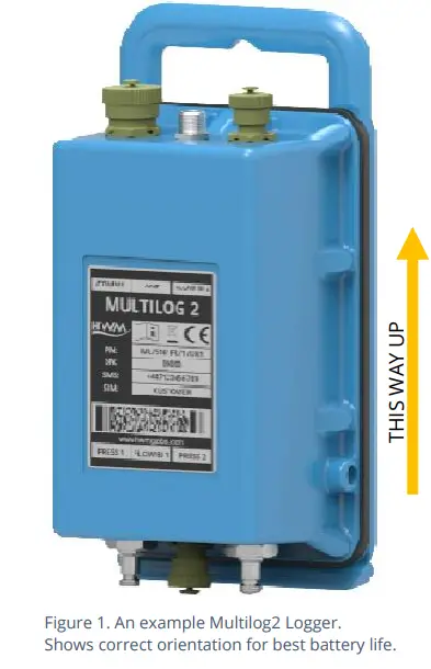
The Multilog2 logger family is flexible in design and can be built to suit a variety of uses. It has a metal enclosure and is of a waterproof construction, using a seal to keep out water.
Un esample hè indicatu in Figura 1.
The logger is powered by a non-rechargeable Lithium battery. The life of the battery can vary with its orientation; refer to Figure 1 for the orientation that will give best battery life.
The top of the logger includes a handle, used for carrying the unit. It also provides a convenient way of hanging the unit in its correct orientation using wall-mounted brackets or other fixing methods.
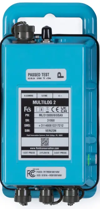
Diverse etichette sò prisenti nantu à u logger. Questi include:
- The nameplate label, which includes the logger part-number, its serial number, and an ‘SMS number’ (an identifier for the logger, in the form of a telephone number).
- Etichette d'identificazione di l'interfaccia.
The logger has waterproof electrical connectors for attaching sensors and the antenna. These can be present on two surfaces (top and bottom). The interfaces installed, and their position, will vary between model-number supplied. Follow the labels to identify interfaces.
A pressure interface may also employ a built-in pressure transducer with a quick-release connector. This is for direct connection to a pipe (or hose).
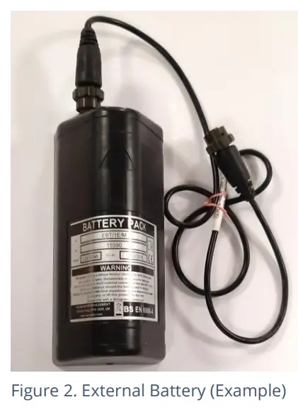
BATTERIA ESTERNA (OPZIONE)
Most Multilog2 models have a connector that allows an External Battery to be connected. These provide the logger with additional power capacity.
Un esample hè indicatu in Figura 2.
Diversi capacità di bateria sò dispunibili.
Always use HWM supplied batteries to ensure compatibility and safety. Ensure the cable supplied with the battery is suitable for the external power connector fitted to your logger. (6-pin and 10-pin connector versions are available. See also section 2.7).
(Per situazioni induve hè necessariu l'usu di una batteria esterna, cunsultate u vostru rappresentante HWM).
OPERAZIONE LOGGER
- The logger software is designed to minimize battery use and thereby prolong the expected battery life. However, battery life is also affected by user-programmablesettings. The user is advised to set the logger tasks and sample frequenze à i requisiti minimi di l'usu previstu per gestisce a putenza di a batteria in modu efficace.
- Induve furnitu, a putenza di a bateria esterna hè aduprata per allargà a vita di a bateria di u logger o per permette cumunicazioni più frequenti cù u servitore host.
- U logger hè normalment speditu da a fabbrica in un statu inattivu (riferitu cum'è
"modu di spedizione", o "modu di sonnu") per priservà a vita di a bateria. - When activated (see section 3), the logger will initially go into the state of “Waiting” (for a short time). Then it will go into the state of “Recording” and begin repetitive logging of measurements from the various sensors fitted to the unit, according to its configuration and settings.
- U logger opera cù dui periodi di tempu, cunnisciutu com'è "sample period" è u "log period". Serà sample i sensori à u sample rate per creà misurazione pruvisoriu samples; questu hè un travagliu di fondo ripetitivu. Dopu à piglià parechje misura samples, qualchi funzione statistiche pò esse appiicata ozzione à pruduce un datapoint chì hè logged (salvatu) à u ritmu log; questi formanu e misurazioni arregistrate (registrate) è sò salvate in una zona di memoria chì hè chjamata "registrazione primaria". U periodu di log hè sempre un multiplu di u sampu periodu.
- Se u logger hà a funzione attivata, pò ancu esse cunfigurata per salvà occasionalmente dati supplementari in una zona di memoria di "registrazione secundaria" (vede a sezione 2.4), (per esempiu, dati s).ampguidatu à una frequenza più altu, cum'è cù l'usu di u "sample period" invece di "log period").
Nota: Questu ùn hè micca dispunibule nantu à tutte l'unità furnite è deve esse disposti attraversu u vostru rappresentante di vendita prima di fà un ordine; hà implicazioni in quantu à a vita di a bateria prevista di l'unità.
The logger will also have daily tasks at set times, such as uploading its unsent data over the internet. When sending data, the logger waits to receive confirmation from the server that the data was received without error; If confirmation is not received, it will re-send the data at the next call-in time.
U logger pò esse programatu per monitorà e dati per certi mudelli o cundizioni è pò mandà un missaghju si deve detectà un match. Comu regula, questu hè utilizatu per stabilisce una cundizione chì pò esse indicazione di "alarma". U messagiu pò esse mandatu sia à u servitore (a destinazione di solitu) sia à un altru dispositivu.
LOGGING ENHANCED (OPZIONI)
Section 2.3 gave a description of logger operation that is available as standard on most Multilog2 logger models; The logger normally samples data at the set sample period, è registra punti di dati à u periodu di logu stabilitu. In ogni casu, certi mudelli offrenu l'opzioni per fà registrazioni supplementari (di dati registrati) à s più altu di u normaleampi tassi di ling. I dati supplementari sò registrati in l'area di memoria di "registrazione secundaria".
These features are sometimes referred to as “Enhanced Network” logging and “Pressure Transient” logging; Collectively they are referred to as “Fast Logging”. The ‘Enhanced Network’ and ‘Pressure Transient’ loggers (both being based on the Multilog2 design), have the named option available as standard.
Nota: The feature can only be installed by the factory at the time of build. The options must therefore be specified at the time of ordering, along with the required maximum samptarifa di ling.
supplementu sampling hà implicazioni per u cunsumu di energia è pò esse bisognu di l'usu di batterie esterne per scuntrà a vita di serviziu necessaria.
E funzioni di logging veloce di u logger ponu esse disattivate durante a cunfigurazione di logger. Induve attivatu, u logger hà duie strategie per trattà a memoria chì diventa piena. Sia u logging veloce fermarà, o dati più vechji ponu esse scritte sopra. Fate a scelta chì avete bisognu durante a stallazione.
Micca tutti i tipi di sensori sò capaci di travaglià à altu sampfrequenze ling. A funzione hè dunque di solitu stabilita per travaglià cù sensori analogichi, cum'è un transducer di pressione.
Logging rapidu hè spessu usatu per monitorà i fluttuazioni di pressione in a reta di supply supply d'acqua.
For Multilog2, ‘Enhanced Network’ logging and ‘Pressure Transient’ logging are mutually exclusive settings (only one can be used). Each has a different operation.
Logging di Rete Enhanced:
- Questa opzione permette à certi avvenimenti di creà una registrazione secundaria.
- A registrazione sarà fatta à u fondu samptarifa di ling.
- L'arregistramentu pò esse un unicu canale o pò include canali supplementari (se u sensoru pò trattà cù a velocità).
- U massimu sampling rate hè limitata à una frequenza di 1Hz.
Logging transitorio di pressione:
- Questa opzione permette à certi avvenimenti di creà una registrazione secundaria.
U logger hà memoria supplementaria per via di a quantità di dati chì devenu esse almacenati. - L'arregistramentu serà fattu à l'asampuna velocità di ling di 1Hz o una di una selezzione di frequenze più alte, finu à 25Hz.
- On Multilog2, up to two channels can be used. Each of these must be for a pressure sensor. The sensors must be allocated to channel 1, or channels 1 & 2.
E registrazioni ponu esse impostate per esse in tempi specifichi o in risposta à diversi avvenimenti di alarme o un cambiamentu in un Status Input (vale à dì, attivatu da un switch output da un equipamentu esternu).
INTEGRAZIONE SERVER - ALMACENA E VIEWING DATA
The Multilog2 logger includes an interface (referred to as a modem) that provides access to the internet via the cellular mobile communications network. A SIM card is used to give access of the network.
I dati di misurazione sò inizialmente almacenati in u logger, finu à u prossimu tempu di call-in. I dati ponu esse caricati à u servitore cù un furmatu criptatu. Di genere, u servitore utilizatu per riceve è almacenà e dati serà un HWM DataGate server, anche se altri servitori ponu esse utilizati in cunghjunzione cù u software HWM.
I dati di logger pò esse viewed utilizendu a viewing portale chì hà accessu à i dati almacenati in u servitore. (Consultate a guida d'utilizatore pertinente per i dettagli di cumu e vostre dati viewer pò esse usatu view i dati di logger).
Nota: Multilog2 loggers supporting WITS protocol behave differently to the above.
These loggers do not use DataGate but communicate with a WITS Master Station. The data can be viewed only by use of the WITS system.
DATAGATE SERVER / DATA VIEWING PORTALS
Quandu hè integratu cù HWM's DataGate server, i dati di misurazione di u logger ponu esse almacenati in u centru è dispunibuli per l'utilizatori via a viewportale (websitu). U servitore di almacenamiento di dati pò trattà a ricezione è l'almacenamiento di dati da una sola unità, o da una flotta intera di loggers.
Viewin Registrazioni Primarie:
I dati da u vostru logger (s) pò esse vieweditatu à distanza / graficamente da qualchissia autorizatu à fà cusì, cù un contu d'utilizatore adattatu (è una password) utilizendu un standard web- navigatore.
HWM hà una selezzione di websiti chì ponu esse usatu view dati logger. A megliu scelta di webU situ dipende da u tipu di sensori utilizati cù u logger.
A websitu cù una data generica viewer can show data graphically, but only for one logger at a time, installed on one site.
A websitu chì pò mustrà una flotta di loggers, ognunu cù u listessu tipu di sensore, pò spessu presentà e dati in una manera più significativa à l'utilizatore, cù infurmazioni supplementari utili (per esempiu, una mappa chì mostra i loggeri di logger). Cusì, a websitu pò dà una stampa di u statu attuale di parechji siti à un tempu.
Consultate a guida di l'utente IDT o a guida di l'utilizatori di u sensoru per i dettagli di quale viewu portale ing hè u più apprupriatu per aduprà. In alternativa, discute stu prublema cù u vostru rappresentante HWM.
U DataGate server pò ancu invià qualsiasi alarme ricevute da u logger à tutti l'utilizatori chì anu abbonatu à elli; un missaghju di alarme logger pò dunque esse distribuitu à parechje DataGmanghjatu utilizatori.
DataGate pò ancu esse utilizatu (per accordu cù u vostru rappresentante di vendita) per esportà e dati di logger à altri servitori.
Una certa configurazione amministrativa di u servitore è di u viewU portale ing hè normalment necessariu per facilità a ricezione, l'almacenamiento è a presentazione di dati di logger in modu correttu. (Configurazione è usu di u DataG(o qualsiasi altru servitore) ùn sò micca cuparti da sta guida d'utilizatore).
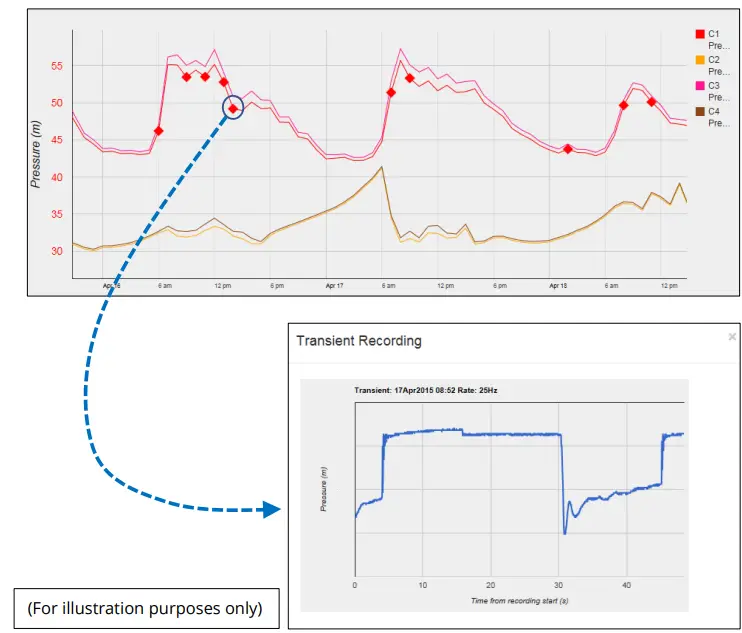
Viewin Registrazioni Secundarie:
Per i siti chì anu mudelli di logger cù Logging Fast inclusu, e registrazioni secundarii puderanu esse fattu. Questi sò ancu almacenati in u servitore.
I vostri dati viewer will have a means of displaying secondary recordings.
It may, for example, mostra un marcatore nantu à a traccia principale per indicà u puntu induve e dati veloci sò dispunibili (per esempiu, induve hè accadutu un transitorio). Cliccate u marcatore per furnisce un close-up view di u transitori.
Viewing location fix (GPS track):
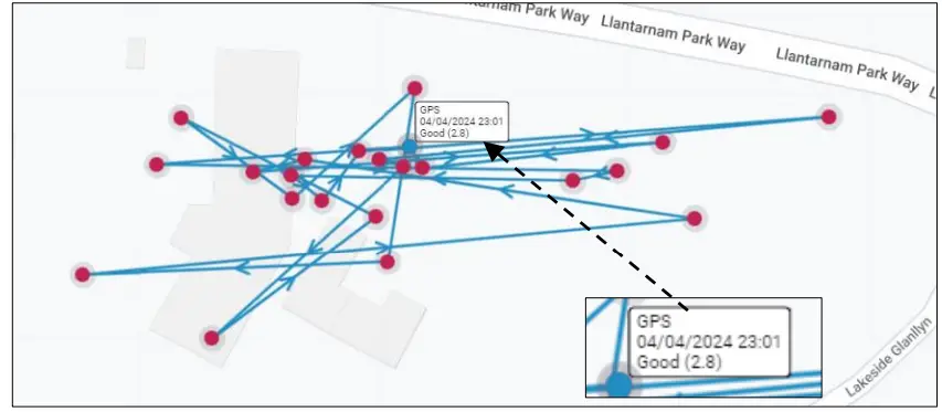
For logger models that include GPS position fix capability, the server will provide a facility to track the location history of the logger. Details of the GPS location fix can be found, typically by selecting one of the shown points. The quality of the location fix will be shown as a number. (This is known as a DOP value. Refer to the table below).
| Valore | Grade | Descrizzione |
| <2 | Eccellente
/ ideal |
Excellent confidence in location fix accuracy. |
| 2-5 | Bene | Good confidence in location accuracy / reliable result. |
| 5-10 | Moderate | Moderate confidence in location accuracy. A more open view of the sky or acquisition period may improve. |
| 10-20 | Fiera | Low confidence level in location accuracy. Indicates a very rough estimate of location. |
| > 20 | Pauvre | Poor confidence of accuracy of location. The measurement should be discarded. |
ACCESSORI DI INSTALLAZIONE
L'accessori (antenna è supporti per a stallazione di l'unità) sò dispunibuli per adattà à diverse situazioni di stallazione; discute a dispunibilità cù u vostru rappresentante HWM.
COMMUNICATIONS INTERFACES AND PROGRAMMING CABLES
To communicate with the Multilog2 logger, a programming cable is required. There are two connector options available in the logger family for making this connection (10-pin or 6-pin); only one of these alternatives will be fitted. Use a programming cable that matches the connector type on the logger.
On Multilog2, the connectors used for communications are frequently shared; they also include the connections required for fitting an external battery (see section 2.2). Because of space limitations, the label may not indicate this (e.g., It may simply be labeled “COMMS”).
A typical connector used for communications and its matching communications cable is shown in Figure 3.
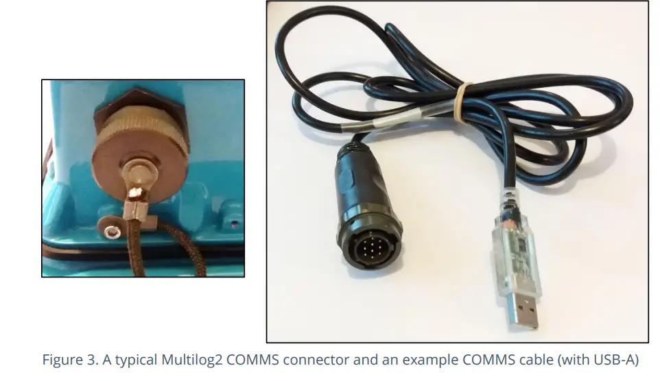
The connector of the communications cable will only include the pins required for communications purposes.
To use the communications cable, temporarily remove any existing connector, and re-connect it when finished. Alternatively, an adaptor (Y-cable) can be inserted to be able to support the logger using both functions together.
Attach the Comms cable to the logger, and then complete the connection to the IDT host using one of the methods described in section 2.8.
Examples of suitable programming cables are given below:
- 10-pin : COM AEUSB (USB to RS232 comms cable).
- CABA2075 (direct USB comms cable).
- 6-pin : CABA8585 (direct USB comms cable).
COMPLETING THE COMMUNICATIONS PATH
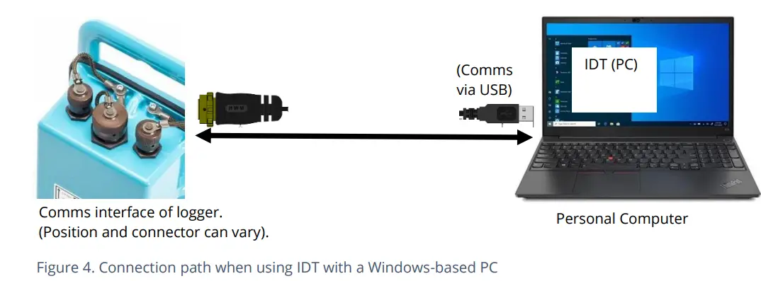
For IDT to communicate with the logger, first select the appropriate cable and connect it to the COMMS connector of the logger, as described in section 2.7. The USB-A end of the programming cable should be used to connect to the IDT host by using one of the following methods:
IDT – USED WITH A PC (& WINDOWS).
Prima di l'usu, u PC deve avè u strumentu di prugrammazione IDT (versione PC) installatu.
L'estremità USB-A deve esse cunnessa direttamente à un portu USB-A di u PC (o à un portu USB-B o USB-C via un adattatore adattatu). Vede a Figura 4.
IDT APP – USED WITH A TABLET (ANDROID) / USB OPTION
Certain Android-based Tablet devices (which must have an available USB port) are able to use this method. (For latest information about known compatible devices, contact your HWM representative).
Prima di l'usu, u dispusitivu mobile deve avè u software di l'applicazione IDT installatu.
The USB-A end should be plugged directly into a USB-A port of the tablet (or to a USB-B or USB-C port via a suitable adaptor). Refer to Figure 5.
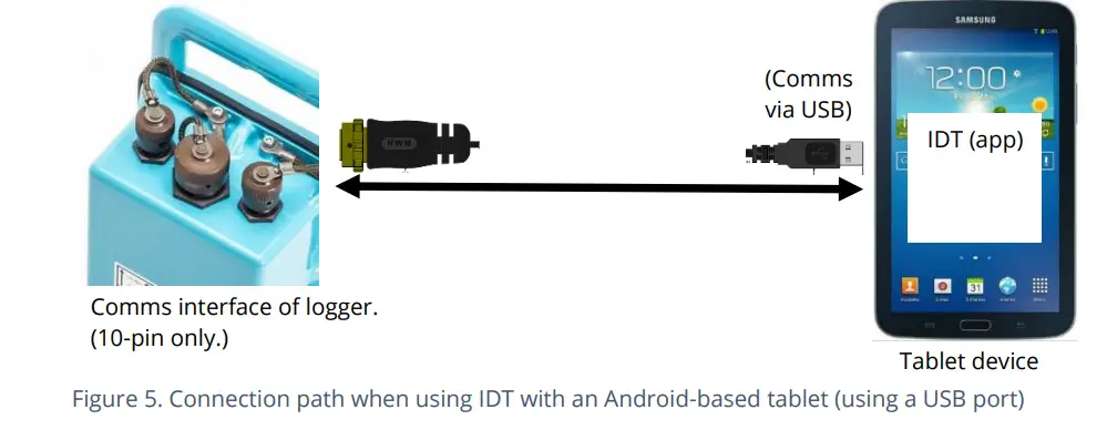
This connection method is only compatible with a 10-pin logger connector and using the COM AEUSEB (USB to RS232) comms cable, or CABA2080 (USB to RS232) Y-Cable.
IDT APP – USED WITH A MOBILE PHONE OR TABLET / BLUETOOTH OPTION
Certi telefoni cellulari o tablette (chì devenu esse basati nantu à Android o iOS è supportà a radio Bluetooth) sò capaci di utilizà stu metudu. (Per l'ultime infurmazioni nantu à i dispositivi cumpatibili cunnisciuti, cuntattate u vostru rappresentante HWM).
Prima di l'usu, u dispusitivu mobile deve avè u software di l'applicazione IDT installatu.
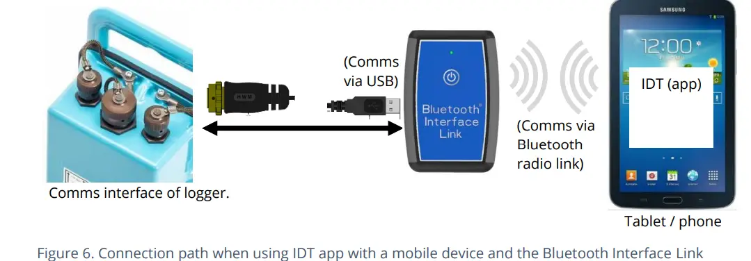
The connection path (refer to Figure 6) makes use of a communications adapter known as the HWM ‘Bluetooth Interface Link’. Connect the logger end of the communications cable to the logger. Then the USB-A end of the communications cable should be plugged into the USB-A port of the Bluetooth Interface Link unit. The device should be turned on during use. The IDT app is required to be paired to the Bluetooth Interface Link unit prior to communication with the logger. The Bluetooth Interface Link handles protocol translations and flow control of messages between the logger
(via the comms cable) and the radio link.
ATTIVITÀ U LINK LOGGER E CUMUNICAZIONI
L'interfaccia di cumunicazione hè sempre monitorata per l'attività è u logger risponderà di solitu, à menu chì ùn sia occupatu à cumunicà cù a rete cellulare.
PROCESSU DI ATTIVAZIONE LOGGER (PER U PRIMU USU)
Quandu hè speditu da a fabbrica, l'unità hè in "modu di spedizione" (disattivatu; micca logu o chjamatu). Stu modu hè adattatu per u trasportu o u almacenamentu à longu andà. Per utilizà u logger, prima deve esse attivatu.
U prucessu per fà questu dipende da l'impostazione di u logger per a riattivazione di a registrazione. Diverse opzioni di impostazione sò dispunibili (tempu specificatu, à a cunnessione di una batteria esterna, à l'attivazione di un interruttore magneticu, "subitu").
Most loggers are set to start ‘immediately’ upon having their settings read by IDT and then saved back to the unit.
Once activated, the logger will initially go into the state of ‘Waiting’ (for a short time). Then it will enter a status of ‘recording’, where it is executing its repetitive logging functions.
U metudu dipende da a versione di IDT aduprata:
- For IDT (PC), the user can do this manually (even if no program changes are required). (Refer to the IDT user-guide for the steps required to read the logger program and then to save it back to the unit using the ‘Setup Device’ button).
- Per l'app IDT, l'utilizatore pò ancu fà questu manualmente via un buttone "Start Device". Inoltre, l'app verificarà i prublemi potenziali ogni volta chì l'utilizatore effettua una disconnessione cuntrullata di u logger da l'app, cumpresa una verificazione di un logger chì ùn hè ancu attivatu / in registrazione.
Prima di lascià u situ, verificate chì u logger sia statu cunfiguratu currettamente per a registrazione, i travaglii di chjama è chì sia in un statu di "Registrazione" (registrazione). Cunsultate a guida di l'utente IDT per una guida nantu à cumu verificà questi punti.
INTERFACES AND SENSOR TYPES (SUMMARY)
Nota: U supportu per interfacce o funzioni specifiche varieghja è dipende da u mudellu furnitu.
I sensori furniscenu infurmazioni per diversi paràmetri fisichi, è sta informazione hè trasferita à u logger per via di una interfaccia elettrica approprita.
Ogni interfaccia hà assuciatu paràmetri di logger per inizià a misurazione è ancu per interpretà currettamente i dati numerichi ottenuti. IDT hè utilizatu per gestisce i paràmetri.
Wired connections are made to the logger via a connector mounted through the logger case. Various sizes are available and can contain either pins or sockets. Some examples are shown in Figure 9 and Figure 8. A dust-cap is available as an option to keep unused connectors free of water and debris (see Figure 7).
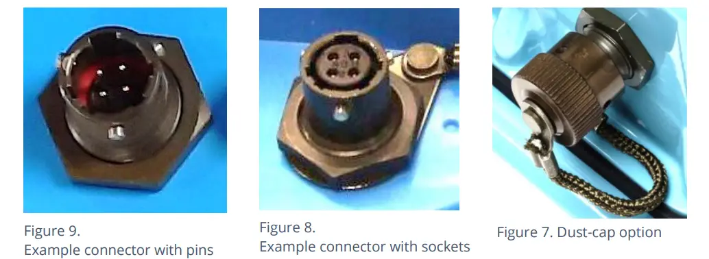
Some connectors are single-purpose in nature (e.g., For connection of a single sensor). However, other connectors may be multi-purpose (e.g., Having both a connection for a programming cable and also for the supply of power from an additional battery).
Where a connector is multi-purpose, a Y-adapter cable may be required to split out the various functions.
For water pressure measurement, the electrical connection to the sensor may be made via a standard electrical connector. This interface is known as an “External Pressure” type. It allows a cabled pressure transducer (sensor) to be connected to the logger. HWM can provide a variety of cabled pressure sensors with the appropriate connector for the logger.
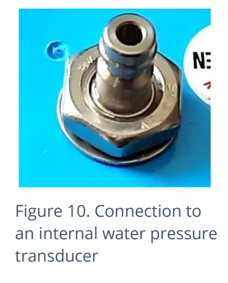
An alternative for water pressure measurement is for the transducer (sensor) to be built into the unit, as shown in Figure 10. This logger interface is known as an “Internal Pressure” type. It allows pressurized water to be connected to the logger directly, via the use of hoses fitted with a quick-release connector.
Per l'antenna, hè utilizatu un altru tipu di connettore. Vede a sezione 5.18.
The Multilog2 supports a variety of sensors and parameter measurements. Exampi sò datu quì sottu: (Dipende da u numeru di mudellu urdinatu).
- Pressione. Examples: – Direct connection to an internal transducer (referred to as an ‘internal’ pressure sensor). -Electrical connector for a wired transducer(referred to as an ‘external’ pressure sensor).
- Distanza to a water surface Example: – By using a SonicSens2 sensor. -By using a SonicSens3 sensor.
- Acqua depth.Examples: – By using a SonicSens2 or SonicSens3 sensor. -By use of a submerged pressure gauge.
- Acqua leak detection (from pressurized water pipes).Examples: – By use of a HWM Leak-Noise Sensor or Hydrophone.•Water (or Gas) Consumption (Flow rate / total consumption).Examples: - Diversi canali 'Flow' sò dispunibuli per adattà à una varietà di formati di output di impulsi di metru.
- Temperature.ExampLe: – By use of a PT100 temperature sensor.
- Status InputExample: - Per detect un interruttore apertu / chjusu.
- Status Output. Examples: – Pulse replication of Status Inputs. -To activate some external equipment.
- GPS input (communication from Global Positioning System satellites). Examples: – To determine current time (high accuracy).-To determine current location / confirm still at installation site.
- 0-1 V input.(or 01-10V)(This is a generic sensor interface.The logger supports inputs from externally powered sensors).
- 4-20 mA input. (This is a generic sensor interface.
- MODBUS
- SDI-12The logger supports inputs from externally powered sensors Optionally, the logger can provide power to compatible sensors). (This is a widely used interface for sensor communications. The logger supports inputs from externally powered sensors. Optionally, the logger can provide power to compatible sensors). (This is a widely used interface for sensor communications. The logger supports inputs from externally powered sensors).
- (Altri). Cuntattate u vostru rappresentante di vendita per più infurmazioni o per discute i vostri bisogni.
For any given parameter, several sensors may be available with different types of electrical interface. Sensors provided by HWM will include a cable with a suitable connector for the supplied Multilog2.
INSTALLAZIONE
SUMARIO DI I PASSI DI INSTALLAZIONE
- Verificate chì una valutazione di u travagliu sia stata fatta è chì tutte e misure di sicurezza sianu in piazza. (Per esempiu, precauzioni di sicurezza, vestiti è/o equipaggiamenti di prutezzione aduprati).
- Check the logger is suitable for use at the installation site.
- Check that you have the required sensors and antenna.
- Cunsiderate induve l'equipaggiu serà situatu in u spaziu dispunibile è chì tutti i cables è i tubi sò di una lunghezza adattata.
- Verificate i raccordi sò dispunibili per cunnette à qualsiasi puntu di misurazione di pressione.
- U logger, i cavi è i sensori deve esse tenuti luntanu da fonti d'interferenza elettrica cum'è mutori o pompe.
- I cavi è i tubi duveranu esse instradati è assicurati per ùn causà periculi. Ùn permettenu micca chì alcun equipamentu si appoghjanu nantu à i cavi, i connettori o i tubi, postu chì u dannu da schiacciamentu pò esse.
- Selezziunate u cavu di prugrammazione adattatu per u logger è attaccatelu à u connettore COMMS di u logger. Cumpiite u percorsu di cunnessione à u dispusitivu host IDT (vede e sezzioni 2.7 è 2.8). Aduprate IDT per leghje i paràmetri di u logger. (Riferitevi à a guida di l'utente IDT per guida ogni volta chì hè necessariu).
- Aghjurnate u firmware di logger (se necessariu).
(Refer to the IDT manual for guidance; consider downloading any existing data from the logger prior to upgrade). - Aduprate IDT per verificà o mudificà i paràmetri di logger esistenti.
- Prugrammate un fusu orariu lucale in u logger (verificate o mudificate).
- Stabilisci intervalli di tempu per fà e misurazioni (sampl'intervallu è l'intervallu di log). Duveranu esse cunfigurati per adattà à i requisiti di registrazione specifichi di a vostra applicazione (minimizà sampling rates per priservà a vita di a bateria).
- Verificate / mudificate i paràmetri di u canale per pruduce misureample è i punti di dati richiesti da ogni interfaccia.
- Configure the logger channel to match the sensor or other equipment that the logger connects to.
(Check units of measure are correct, etc) - Assicuratevi chì u sensoru hè mappatu à u numeru currettu di u canale di output; Questu hè un identificatore utilizatu quandu si carica i dati di misurazione registrati à u servitore. (vale à dì, i numeri di u Canale devenu currispondenu trà logger è DataGmanghjatu).
(Note: For loggers using WITS protocol, requirements are different; refer to the guidance in the WITS supplement, MAN-147-0017). - Applica tutte e funzioni statistiche richieste à a misura di fondo samples per pruduce punti di dati registrati (valori salvati).
- Where required, undertake the setup of any additional options related to the channel. (E.g., add an initial meter reading, pulse replication setting, sensor calibration; these will be dependent on sensor and logger use).
- Per i sensori di pressione, cunnetteli elettricamente ma espone u sensore à a pressione atmosferica lucale è riazzeralli (usendu IDT) prima di cumincià à fà una cunnessione à u puntu di misurazione.
- Installa (pusizioni è cunnette) i sensori à u so puntu di misurazione.
- Purga ogni cunnessione à l'acqua.
- Induve necessariu, insulate ogni tubu pienu d'acqua cunnessu à i trasduttori di pressione per pruteggiri da u gelu. (I coperchi di tubi isolanti ponu esse furniti nantu à dumanda à un costu supplementu o acquistati in u locu da una ferramenta).
- Assicuratevi chì tutti i cunnessione elettriche fatte in situ sianu secche, durevuli è impermeabili.
- Aduprate IDT per:
- Verificate chì u logger è i sensori funzionanu currettamente. (Certi ponu esse fatti prima di l'installazione; altri dopu l'installazione).
- Configurate u logger per qualsiasi alarme. Cunsiderate e cundizioni per attivà i missaghji d'alarma è ancu e cundizioni per l'alarma per sguassà.
- Verificate / mudificate i paràmetri di cumunicazione di u dispusitivu, secondu i bisogni:
- Paràmetri SIM (parametri per dà accessu à a rete cellulare).
- Impostazioni di u modem (tecnologia di rete cellulare).
- Paràmetri di consegna di dati (datti di cuntattu di u servitore).
- Tempi di call-in è paràmetri di protokollu.
- Verificate chì tutte e mudifiche à i paràmetri sò state salvate prima di lascià u situ. Verificate chì u logger sia in statu di "registrazione".
- Induve u logger hà una cunnessione di l'antenna GPS, installate (pusizioni è cunnette) l'antenna GPS per piglià e cumunicazioni satellitari.
- Use IDT to test the GPS installation is correctly working (GPS test).
- If used for obtaining a location fix, setup GPS location fix schedule and any GeoFence alarm requirements.
- Install (position and connect) the antenna for server communications.
- Use IDT to test the cellular communications performance.
- Ensure details of the site of logger deployment are recorded.
- (L'amministrazione di u servitore puderia esse trattatu da u persunale di l'uffiziu, o l'installatore puderia utilizà l'app HWM Deployment).
INSTALLING THE LOGGER
The logger must be mounted in a suitable location where the sensors to be attached can reach their intended installation points. Position loggers, sensors, and antenna away from sources of electrical interference such and motors or pumps. Cables and hoses should be routed without causing any hazards. Do not allow any equipment to rest on hoses, cables or connectors as crush damage can result.
The logger should be installed in the orientation shown in Figure 1 for optimum battery performance.
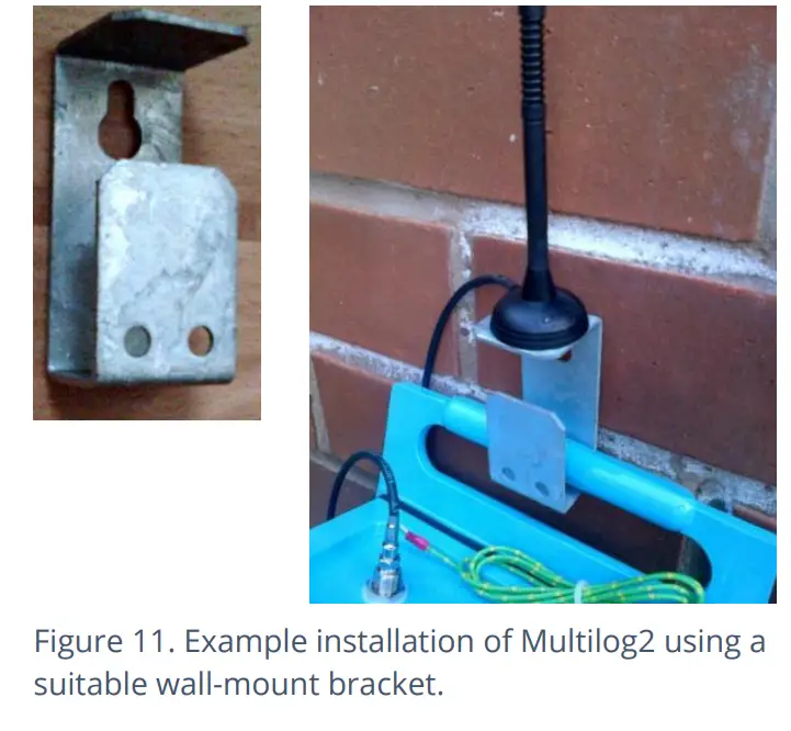
MONTAGE À MUR
The Multilog2 can be secured to a wall using a suitable bracket, an example of which is shown in Figure 11. Ensure the wall and fixings used are able to bear the weight of the logger and cables attached.
The bracket used may offer a potential mounting location for the antenna, although the installer should seek to find the optimal location for the antenna within the installation.
ELECTRICAL CONNECTIONS TO THE LOGGER
When making electrical connections to the logger (e.g., attaching a connector for a sensor), ensure the connector is correctly fitted. Both parts of the connector should be dry and free of debris. The connectors are keyed to ensure correct alignment of pins and receptacles. Align the sensor to the logger connector and push fully home. Then rotate the outer part of the sensor connector until it engages with the fastening mechanism and locks into place. The connector will then be secure and watertight.
Quandu si sguassate e cunnessione, seguitate i passi inversi di a prucedura descritta sopra. Maneghjate sempre a cunnessione da u connettore; ùn tirate micca u cavu perchè questu puderia causà danni.
Fate chì tutti i cavi ùn causinu micca periculi potenziali è fissateli in u locu cù fascette adatte.
For antenna, follow the steps given in section 5.18.
SETTINGS DI FABRICA
Nota: U logger hà generalmente paràmetri preprogrammati da a fabbrica prima di u trasportu. Tuttavia, l'installatore hà a rispunsabilità di cunfirmà i paràmetri sò adattati per l'usu in u situ installatu.
Se avete esigenze specifiche, questu pò esse discutitu cù u vostru rappresentante di vendita HWM à u mumentu di l'ordine di i loggers.
Se necessariu, IDT pò esse adupratu per verificà o fà cambiamenti à i paràmetri di u logger.
Per a maiò parte di l'interfaccia di i sensori, seguite a guida generale in a guida d'utilizatore IDT; u logger hè conforme à a descrizzione è examples of setup provided therein. However, some HWM sensors require specialized setup screens or have their own user-guide which provides further guidance.
SENSORI DI PRESSIONE INPUTS
RE-ZERO FACILITY (PER A PRESSIONE RELATIVA À L'ATMOSFERA LOCAL)
Pressure sensors supplied by HWM normally measure pressure relative to atmospheric pressure. Since there can be some variation in local atmospheric pressure (e.g., due to altitude), the loggers have a facility to re-zero the pressure sensor.
Questu deve esse fattu cù u sensoru espostu à l'aria atmosferica.
Prior to connecting the transducer to the actual measuring point, leave it exposed to air. Then “re-zero” the sensor using the method found in the IDT user-guide.
SENSORE DI PRESSIONE (INTERNU)
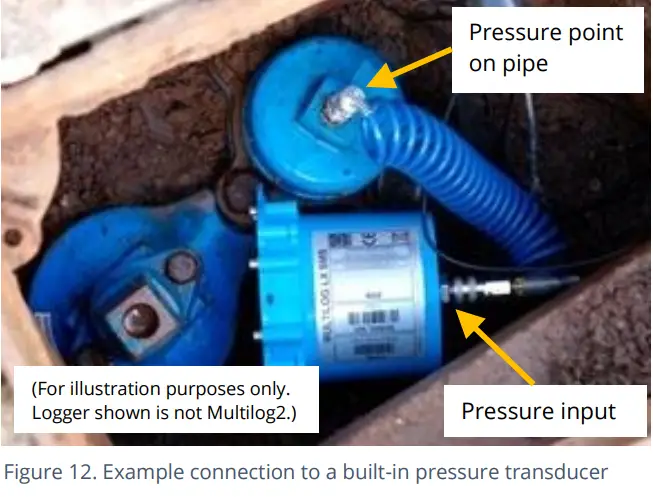
Una entrata di pressione pò esse presentata cum'è un transducer integratu (cum'è mostra in Figura 10, in a pagina 14), chì si cunnetta direttamente à u fluidu per via di un tubu cù un connettore rapidu.
Nota: Ùn cunnette micca u sensore à u puntu di misurazione prima di passà per u prucessu di riazzeramentu (à a pressione atmosferica lucale), se necessariu.
Cunnettete a presa di pressione nantu à a pipa (puntu di misurazione) à u transducer di pressione di u logger cù un tubu di interconnessione adattatu. (Per un example, vede Figura 12.) Assicurà u hose hè bleed, per u funziunamentu currettu.
Questa interfaccia hè calibrata in fabbrica. Nisuna calibrazione in situ hè necessaria.
Nota: Add insulation to the pipe and logger to prevent freezing.
If the water in the hose or the logger itself freezes, there is a danger of permanent damage to the pressure transducer.
SENSORE DI PRESSIONE (ESTERNI)
A pressure input may be presented as an electrical interface, using a 4-pin or 6-pin MIL-Spec connector (see Figure 9 on page 14).
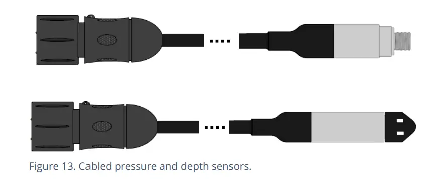
Cabled pressure sensors for the Multilog2 are available from HWM. For most situations, sealed type pressure (or depth) sensors are used, and the sensor will be wired directly to the connector, as shown in Figure 13.
U logger applica temporaneamente u putere à u sensoru ghjustu prima (è durante) di fà una misurazione.
L'interfaccia di u logger serà chjamata "Pressione (20 bar)" (o simile).
U pinout di i connettori hè mostratu quì sottu.
| Pinout di u cunnettore di a paratia di u registratore: Pressione esterna à 4 pin | |||
| A | B | C | D |
| V (+) ; (PWR) | V (+) ; (signale) | V (-) ; (PWR) | V (-) ; (signale) |
| Pinout di u cunnettore di a paratia di u registratore: Pressione esterna à 6 pin | |||||
| A | B | C | D | E | F |
| V (+) ; (PWR) | V (+) ; (signale) | V (-) ; (PWR) | V (-) ; (signale) | GND / Schermu | (micca cunnessu) |
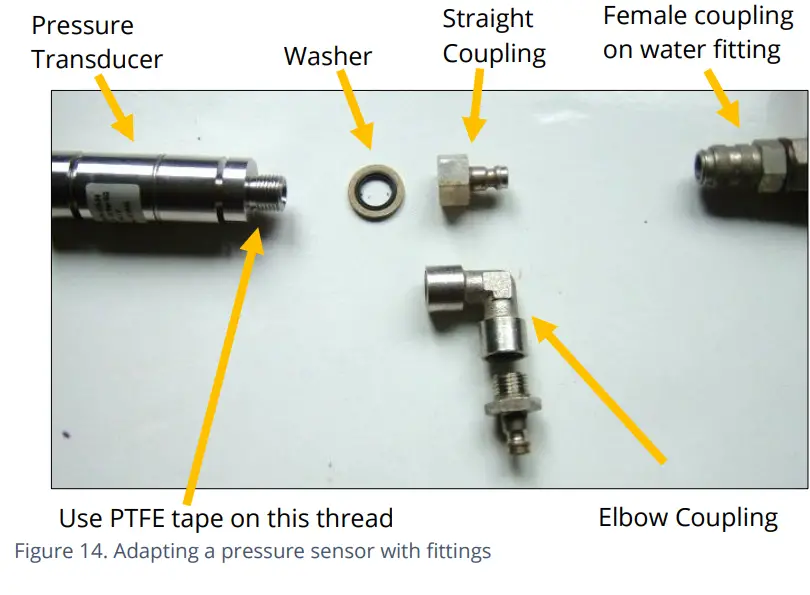
Where a pressure transducer has a threaded end for connection to the pressure measurement point, fittings may be required to modify the connection (e.g., a quick-release connector for connection to a hose). For example, vede Figura 14.
Assemble any fittings prior to connecting to the logger.
Straight or elbow styles of coupling kits are available.
Confirmate chì u logger hà l'interfaccia adatta per u sensor di pressione o di prufundità. Allora cunnette u sensoru à l'interfaccia di logger pertinente.
Nota: Ùn cunnette micca u sensoru à u puntu di misurazione prima di passà u prucessu di calibrazione (vede quì sottu) è dopu re-zero (à a pressione atmosferica lucale).
Per un sensoru di pressione, aghjunghje à u puntu di misurazione è (se applicabile) spurgate ogni tubu di cunnessione.
Per un sensoru di prufundità, u sensoru deve esse ponderatu o muntatu in modu sicuru à u fondu di u canali di l'acqua, usendu un attellu (per esempiu, una piastra di trasportu o un supportu di ancoraggio) se necessariu. U cable deve ancu esse assicuratu in u locu per impediscenu l'acqua in muvimentu di agisce nantu à u cable per tirà u sensoru fora di a pusizione o stressà qualsiasi cunnessione.
Prucessu di calibrazione (aduprendu i valori di calibrazione da u cable):
Prima di utilizà u sensoru, u logger è u paru di sensori deve esse calibrati per dà una lettura curretta.
Stu metudu pò esse usatu da un installatore per accoppià è calibre un sensor di pressione à u logger.
I sensori di pressione / prufundità furniti da HWM sò generalmente valori di calibrazione indicati nantu à u cable (vede a Figura 15). Aduprate IDT per aghjunghje i dettagli da l'etichetta di calibrazione nantu à u cable in u logger usendu a guida in a guida d'utilizatore IDT.
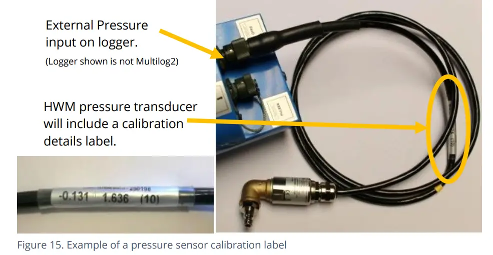
U prucessu di calibrazione deve esse prima di u re-zero di u sensor di pressione.
Dopu avè seguitu u prucessu di calibrazione è u prucessu di re-zero, u transducer pò esse situatu à (o adattatu à) u so puntu di misurazione.
U registratore deve esse cunfiguratu currettamente per fà misurazioni da u sensore. Cunsultate a guida di l'utente IDT per più dettagli.
Prucessu di calibrazione (aduprendu pressioni applicate):
Stu metudu pò esse adupratu da un centru di serviziu autorizatu per accoppià è calibrà un sensore di pressione à u logger.
U metudu hè custituitu da applicà pressioni di riferimentu à u transducer è custruisce una tabella di valori di calibrazione.
ENTRATA SENSORE DI FLUSSO (COLLEZIONE DI IMPULSI DI METER)
Sicondu u mudellu furnitu, u logger pò avè da 0 à 6 ingressi di flussu. Quessi sò ingressi digitali, cuncepiti per rilevà a cundizione aperta o chjusa di un interruttore (attivatu da u contatore installatu). Per aduprà u(i) canale(i) di flussu, u logger deve esse cunfiguratu (cù IDT) per sapè ciò chì rapprisenta ogni impulsu di u contatore.
Spiegazione di i canali di flussu è di i signali di input
Flow of a fluid in a pipe is usually detected by a meter, which produces pulses related to the volume of fluid passing through it. There are several types of meters; some can detect both forward flow and reverse flow (bi-directional flow); some can detect flow in one direction only (uni-directional flow). There are therefore several ways of implementing the meter pulse output signals from a meter. Your logger must have the correct interface and settings for the signaling from the meter to be compatible with it.
The Multilog2 Flow inputs sometimes require two input signals in order to work with the meter-pulse signaling of certain meters. A pair of inputs can therefore sometimes be configured to operate as a single channel. Other meter types only require one signal, so the pair of inputs can operate as two separate channels.
The pair of Flow signals can be labeled in one of the following ways:
| Nomi di signali alternativi | ||||
| Pair of FLOW
signali |
Ingressu di flussu 1 | Flussu 1 | Legumi | Flussu (in avanti) |
| Ingressu di flussu 2 | Flussu 2 | Direzzione | Flussu (Inversu) | |
| Cumunu | GND | |||
The labeling depends on the factory default for the configuration of the Flow channels on your logger model-number, but sometimes alternative types of configuration can be achieved by changing logger settings.
Induve u logger hè pre-configuratu da a fabbrica per pruduce solu 1 canale di flussu (datapoint stream), u paru di input pò esse usatu in una di trè modi diffirenti:
(1) Input 1 can be used with a Uni-directional meter (one which only measures forward flow / consumption).
Per l'usu in questa cunfigurazione:
• Input 1 acts to collect meter pulses, and
l'entrata 2 hè generalmente lasciata scollegata (o assignata per esse aduprata cum'è una 'T'amper Allarme', o adupratu cum'è input di Status).
(2) L'entrate 1 è 2 ponu esse aduprate cum'è una coppia cù un misuratore bidirezionale (unu chì pò misurà sia u flussu in avanti sia quellu in daretu).
Per l'usu in questa cunfigurazione:
• Input 1 acts to collect meter pulses, and
• input 2 is used for the flow direction indication from the meter
(open = forward flow, closed = reverse flow).
(3) L'entrate 1 è 2 ponu esse aduprate cum'è una coppia cù un misuratore bidirezionale (unu chì pò misurà sia u flussu in avanti sia quellu in daretu).
Per l'usu in questa cunfigurazione:
• Input 1 acts to collect meter pulses (forward flow direction), and
• input 2 acts to collect meter pulses (reverse flow direction).
Where the logger is pre-configured by the factory to produce 2 Flow channels
(flussi di punti di dati), a coppia d'ingressi pò esse aduprata cum'è 2 canali d'ingressu di flussu unidirezionali indipendenti (canali 1 è 2).
Ogni entrata pò esse aduprata cù un contatore unidirezionale (unu chì misura solu u flussu / cunsumu in avanti).
VIA UN CONNETTORE LOGGER 4-PIN BULKHEAD
Multilog2 Flow signal inputs are presented on a 4-pin connector (see Figure 9 on page 14). Each connector has a pair of Flow signal inputs.
U pinout di stu connettore hè mostratu quì sottu:
| Pinout di u cunnettore di a paratia di u registratore: Ingressi di flussu à 4 pin | ||||
| Pin | A | B | C | D |
| Segnale | (micca cunnessu) | Ingressu di flussu 1 | Flussu_GND | Ingressu di flussu 2 |
Check the meter to which the logger is going to be connected and ensure its meter pulse signaling method is understood, along with the significance of each meter pulse.
Connect the logger to the meter-pulse outputs of the meter using a suitable cable. If cables with bare tails have to be interconnected, refer to the guidance in section 5.5.
Use IDT to complete the setup, ensuring the logger is correctly set to interpret the meter pulses. If the logger is required to keep track of the meter counter display, take an initial reading of the meter counter and program it into the logger. The logger uploads additional consumption regularly, so a meter reading can be made remotely.
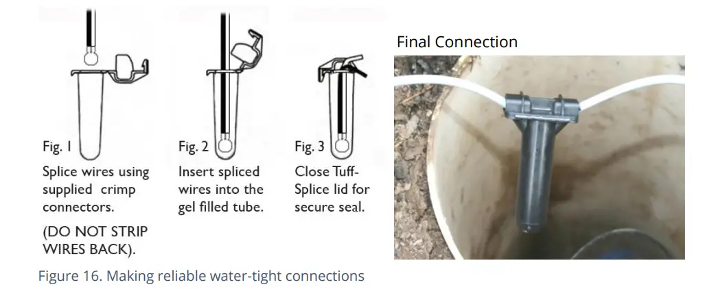
CONNETTING CABLE WIRES UNTERMINATED À L'EQUIPAMENTE
Quandu si usa un cavu senza terminazione, un installatore duverà fà a so propria cunnessione à l'altri apparecchi in situ.
When making a connection to Multilog2 you will normally need to splice the bare tails together. It is important that a waterproof connector housing is used, such as the “Tuff-Splice” enclosure available from HWM.
Nota: Long data connections should always be made using screened cable. The use of screened cable will ensure maximum rejection of interference from outside sources. Always use a common ground point without creating ground loops.
STATUS INPUT
The Status Input pins are a re-purposed use of the Flow input electronics (see section 5.4). A change in the software driver for the connector gives the input pins a different functionality.
L'interfaccia serà etichettata cum'è "Status" o "Doppiu Status".
U pinout di stu connettore hè mostratu quì sottu:
| Logger bulkhead connector pinout : 4-pin Status Inputs | ||||
| Pin | A | B | C | D |
| Segnale | (micca cunnessu) | Status Input 1 | Status_GND | Status Input 2 |
I signali d'entrata di statu ponu esse cunfigurati per un usu generale in a rilevazione di cuntatti di l'interruttore. Questu hà parechji usi.
p.e
- Rilevazione di aperture di porte / finestre / accessu à l'attrezzatura per scopi di sicurezza.
- Un pin "di riserva" nantu à un canale di flussu pò esse adupratu per generà una "t".amper’ alarm in the event that the logger cable is cut or removed from the meter.
(The meter must support this facility by providing a closed loop from the tamper input à u pin di ritornu, Status_GND).
Cunnette u registratore à l'equipaggiu esternu cù un cavu adattatu. Sè i cavi cù code nude devenu esse interconnessi, riferitevi à a guida in a sezione 5.5.
Aduprate IDT per compie a cunfigurazione, assicurendu chì u logger sia cunfiguratu per generà l'allarme desideratu.
OUTPUTS (DIGITAL SWITCH: OPEN/CLOSED)
Multilog2 Outputs are presented on a 3-pin connector (similar to Figure 8 on page 14). Up to four outputs can be supported. Each connector has a pair of outputs.
The interface will be labeled as ‘Dual Output’.
U pinout di stu connettore hè mostratu quì sottu:
| Pinout di u cunnettore di a paratia di u registratore: Uscite à 3 pin | |||
| Pin | A | B | C |
| Segnale | Risultatu 1 | Risultatu 2 | GND |
U logger ùn furnisce micca alimentazione à a surtita. A surtita piglia a forma di un interruttore elettronicu (transistor), chì pò esse apertu o chjusu. Quandu hè chjusu, u percorsu di corrente hè trà u pin di surtita è a terra.
U massimu nominali voltage hè 12V (DC)
A corrente nominale massima hè 120 mA.
Un usu cumunu di i pin di uscita hè per a replicazione di l'impulsi (di l'impulsi di u misuratore chì sò in input à i canali di flussu). Induve questu hè implementatu:
- L'entrata di flussu 1 hè replicata à l'uscita 1
- L'entrata di flussu 2 hè replicata à l'uscita 2
- L'entrata di flussu 3 hè replicata à l'uscita 3
- L'entrata di flussu 4 hè replicata à l'uscita 4
I signali di uscita ponu ancu esse aduprati per attivà apparecchiature esterne.
Per aduprà l'uscite, hè necessariu un cavu adattatu (i requisiti esatti dependeranu di l'equipaggiu cù quale u logger hè adupratu; discute cù u vostru rappresentante HWM). Se i cavi cù code nude anu bisognu di esse interconnessi, riferitevi à a guida in a sezione 5.5.
Aduprate IDT per compie a cunfigurazione, secondu a vostra applicazione per l'output.
BATTERIA ESTERNA
L'usu di una batteria esterna hè facultativa per parechje installazioni, ma pò esse necessaria per sustene u logger per ottene a durata di serviziu necessaria.
Per una durata ottimale di a batteria, orientate a batteria esterna in a so orientazione preferita (vede l'etichetta nantu à a batteria). E batterie sò dispositivi pesanti. Quandu si posiziona a batteria, verificate chì ùn schiaccia micca cavi o tubi in l'installazione. Assicuratevi chì a batteria sia fissata in a so pusizione d'installazione (cusì ùn pò cascà). Poi cunnettetela à u logger.
A cunnessione di u logger per una batteria esterna serà presentata via un connettore (6 o 10 pin) chì hè spartutu cù l'interfaccia di prugrammazione (chjamata "COMMS").
U cavu chì hè adupratu per intercunnette u pacchettu di batterie esterne à u logger includerà solu i pin richiesti per l'alimentazione; i pin assignati per scopi di cumunicazione ùn saranu micca muntati.
A cunnessione di a batteria esterna deve esse temporaneamente disattivata ogni volta chì hè necessariu cunnette un cavu di prugrammazione di u logger.
SONICSENS 3 (ULTRASOUND DISTANCE / DEPTH SENSOR)
Where a SonicSens3 interface is available on your logger, it will have a 6-pin connector, similar to that shown in Figure 8, on page 14.
The interface provides power and communications to the sensor, which measures distance to a fluid surface. By input of other parameters (e.g., distance from the bottom of the water channel) the logger can calculate water depth. It can also derive a variety of other measurements such as flow rates if situated near an open weir.
Consultate a guida d'utilizatore SonicSens-3 (MAN-153-0001) per struzzioni nantu à cumu installà è cunfigurate u sensoru per u funziunamentu.
Nota: Multilog2 loggers are not of an intrinsically safe construction, and so cannot be used within an environment where a potentially explosive atmosphere may be present.
SONICSENS 2 (ULTRASOUND DISTANCE / DEPTH SENSOR)
Where a SonicSens2 interface is available on your logger, it will have a 4-pin connector, as shown in Figure 8, on page 14.
The interface provides communications to the sensor, which measures distance to a fluid surface. By input of other parameters (e.g., distance from the bottom of the water channel) the logger can calculate water depth. It can also derive a variety of other measurements such as flow rates if situated near an open weir.
Consultate a guida d'utilizatore SonicSens-2 (MAN-115-0004) per struzzioni nantu à cumu installà è cunfigurate u sensoru per u funziunamentu.
Nota: Multilog2 loggers are not of an intrinsically safe construction, and so cannot be used within an environment where a potentially explosive atmosphere may be present.
ENTRATA DI TEMPERATURA (RTD - PT100)
The logger may be constructed with a 4-pin connector (see Figure 9, on page14) for connection of a temperature sensor. Typically, this will be a PT100 RTD sensor. The logger interface will be labeled “TEMP” or similar).
U pinout di i connettori hè mostratu quì sottu.
| Logger bulkhead connector pinout : 4-pin Temperature (RTD -PT100) | |||
| A | B | C | D |
| Temp_V + | Temp_S + | Temp_V – | Temp_S – |
| Logger bulkhead connector pinout : 6-pin Temperature (RTD -PT100) | |||||
| A | B | C | D | E | F |
| Temp_V + | Temp_S + | Temp_V – | Temp_S – | GND / Schermu | (micca cunnessu) |
Per utilizà u sensor di temperatura, a calibrazione di l'input hè necessaria.
When ordered with a temperature sensor from HWM, the sensor will have the correct connector fitted for the Multilog2 logger. The logger input will also be factory calibrated for use with the supplied sensor.
INGRESSO LNS (SENSORE DI RUMORE DI FUGA / IDROFONO)
The logger may be constructed with a 4-pin connector (see Figure 9, on page14) for connection of a high sensitivity audio sensor, used for detecting the noise of a leak from a pressurized water pipe.
The interface will be labeled ‘LNS INPUT’ (or similar).
Typically, the sensor will be a Leak Noise Sensor from one of the HWM PR4LNS-1 family. The Multilog2 is also compatible with the Hydrophone-2 sensor (and its earlier version, Hydrophone). Both use the same connector. There are only minor differences in setup of the logger for their use. There are significant differences in their installation methods.
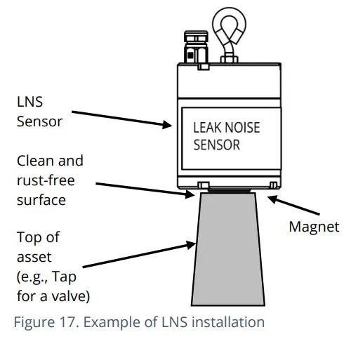
Installazione di u sensor LNS di tippu magneticu:
U logger usa u sensoru per sente i soni pruduciuti da a reta di pipa. Allora usa algoritmi speciali per ghjudicà se una fuga hè prubabile di esse presente vicinu.
U sensoru di l'audio in l'unità LNS hè attaccatu à l'esternu di a rete di tubi per l'usu, di solitu utilizendu un magnetu per attaccà à un asset di pipa metallica (idrante o valvola) in una camera. Vede a Figura 17.
U sensoru deve esse idealmente attaccatu à una superficia superiore di l'assetu, cù u sensoru rivoltu in u sottu. (Questu riduce u risicu di caduta di u sensoru).
Prima di installà u sensoru, pulite u puntu di attache di l'assi è sguassate ogni ruggine da ellu, cù una spazzola di filu; questu assicura un bonu cuntattu cù a pipa (per cunduce u sonu).
Allora cunnette u cable sensor à u logger.
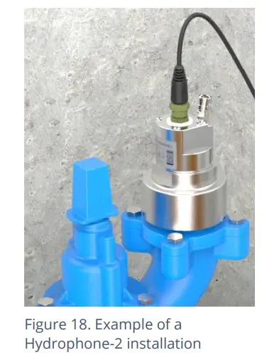
Installazione di u sensoru Hydrophone-2:
U sensoru di l'audio in l'unità Hydrophone-2 cunnetta direttamente à l'acqua in u tubu attraversu un puntu d'accessu, cum'è un hydrant (vede a Figura 18). Questu li dà un intervallu di funziunamentu più longu chì u LNS, in particulare in i tubi di plastica.
Installing the unit into the water network can be a dangerous operation unless carried out correctly. Refer to the Hydrophone-2 user-guide
(MAN-165-0001) for installation and use details.
Cumportamentu di Logger è Server:
The use of a Leak-Noise sensor or Hydrophone can cause some changes (additions) to the logger’s pattern of behavior. This section provides a summary of the loggers use of the sensors; For a detailed explanation, refer to the PermaNet+ with Hydrophone-2 user-guide (MAN-148-0007).
L'output da u logger includerà una varietà di parametri, ognuna di quali serà un canali di datapoint.
I paràmetri di rilevazione di fughe includeranu:
- Livellu
- Prupagazioni
- Leak / No-leak judgment
Per a maiò parte di l'installazione di a rete d'acqua, u logger hà tipicamente eseguitu un ciclu di prova di fuga una volta à ghjornu. Tuttavia, quandu s'utilice per monitorà e parti critiche di a reta di l'acqua, cum'è u troncu principale, un ciculu di prova alternativu hè dispunibule (chjamatu modu "Trunk Main"); Questu eseguisce una prova di valutazione di u rumore più corta assai più frequente, per furnisce una prima indicazione di prublemi potenziali di fuga.
In più di i paràmetri di rilevazione di fughe, u logger pò pruduce altri tipi di dati supplementari, cum'è registrazioni di sonu (audio). files). Quessi sò ancu caricati à u servitore è ponu esse ascoltati remotamente da un utilizatore espertu, per fà un ghjudiziu nantu à se u sonu hè simili à quellu di una fuga d'acqua.
If the logger can find a highly accurate time reference from where it is installed
(e.g., from the cellular communications network or a GPS satellite), a high-accuracy time-stamp serà ligatu à l'audio file.
U servitore pò furnisce a facilità per aggrupà parechji loggers (locali à l'altri) chì anu signalatu una fuga è poi verificate e registrazioni di sonu. Fornisce chì e registrazioni audio sò state fatte esattamente à u stessu tempu, u servitore pò aduprà per pruvà à localizà a pusizioni di a fuga potenziale nantu à a reta di pipa.
L'altri dati chì ponu esse ottenuti da u logger sò l'istogrammi di u rumore (per valutà se un cambiamentu hè accadutu in e caratteristiche di u rumore di pipa recentemente).
ANALOGUE VOLTAGE INPUT (0-1V, 0-10V)
U logger pò esse custruitu cù un connettore à 4 pin (vede a Figura 8, a pagina 14) per a cunnessione di un sensoru chì impiega una volta di output.tage level as a method of signalling. Both a 0-1V and a 0-10V input interfaces are available on Multilog2 but must be specified at the time of ordering.
U logger ùn furnisce micca putere à u sensoru; deve avè a so propria fonte di putere.
U pinout di stu connettore hè mostratu quì sottu:
| Pinout di u cunnettore di a paratia di u registratore: Vol.tagIngressu 0-1V (è 0-10V) | ||||
| Pin | A | B | C | D |
| Segnale | (micca cunnessu) | 0-10V + /
0-1V + |
(micca cunnessu) | 0-10V – /
0-1V - |
Una larga varietà di sensori sò dispunibili cù questa interfaccia.
When ordered from HWM, the sensor will have the correct connector fitted for the Multilog2 logger.
L'installatore duverà aduprà IDT per cunfirmà o aghjustà i paràmetri di u logger per scala currettamente è interpretà i paràmetri fisichi chì u sensoru attaccatu hè utilizatu per detectà.
ANALOGUE CURRENT INPUT (4-20MA)
The logger may be constructed with a 4-pin connector (see Figure 8, on page 14) for connection of a sensor which employs an output current as a method of signalling.
Dui tipi d'interfaccia sò dispunibili:
- Passivu.
- Attivu.
4-20MA (PASSIVE)
Where a ‘passive’ 4-20mA interface is fitted, the logger does not provide power to the sensor; it must have its own source of power.
L'interfaccia di u logger serà chjamata "4-20mA" (o simile).
U pinout di stu connettore hè mostratu quì sottu:
| Pinout di u cunnettore di a paratia di u registratore: Ingressu di corrente (4-20mA) | |||
| A | B | C | D |
| (micca cunnessu) | 4-20 mA + | (micca cunnessu) | 4-20 mA - |
Una larga varietà di sensori sò dispunibili cù questa interfaccia.
When ordered from HWM, the sensor will have the correct connector fitted for the Multilog2 logger.
L'installatore duverà aduprà IDT per cunfirmà o aghjustà i paràmetri di u logger per scala currettamente è interpretà i paràmetri fisichi chì u sensoru hè utilizatu per detectà.
4-20MA (ACTIVE)
Where an ‘active’ 4-20mA interface is fitted, the logger can provide power to a compatible sensor.
L'interfaccia di u logger serà chjamata "4-20mA (Attivu)" (o simile).
U pinout di stu connettore hè mostratu quì sottu:
| Pinout di u cunnettore di a paratia di u registratore: Ingressu di corrente (4-20mA) | |||
| A | B | C | D |
| V+ (PWR) | 4-20 mA + | GND (PWR) | 4-20 mA - |
Una larga varietà di sensori sò dispunibili cù sta interfaccia. Tuttavia, micca tutti anu i stessi requisiti di putenza. U connettore hè capace di furnisce finu à 50 mA di corrente. U vulume di uscitatage hè variabile (da 6.8 V à 24.2 V, in 32 passi), è pò esse impostatu cù IDT.
Per evità danni: Prima di cunnette u sensore, aduprate IDT per assicurà u vulume di uscita currettu.tage per u sensore hè impostu.
The logger does not supply continuous power to the interface, but only activates it for a short time whilst making a measurement. IDT gives access to controls to set the amount of time the sensor has power applied prior to and during measurement. The installer can set these to allow for any initialisation or settling time the sensor requires.
When ordered from HWM, the sensor will have the correct connector fitted for the Multilog2 logger.
L'installatore duverà aduprà IDT per cunfirmà o aghjustà i paràmetri di u logger per scala currettamente è interpretà i paràmetri fisichi chì u sensoru hè utilizatu per detectà.
L'interfaccia pò ancu esse aduprata cù sensori chì anu a so propria fonte d'alimentazione.
ENTRATA SERIE (SDI-12)
U logger pò esse custruitu cù un connettore à 4 pin (vede a Figura 8, in a pagina 14) per a cunnessione à l'equipaggiu chì impiega u metudu SDI-12 di signalazione; Questa hè una interfaccia di dati seriale. L'equipaggiu esternu conduce qualsiasi elettronica di sensori; unu o parechji sensori ponu esse attaccati à questu.
U logger ùn furnisce micca alimentazione à l'interfaccia SDI-12. L'equipaggiu / sensore cunnessu deve avè a so propria fonte d'alimentazione.
L'interfaccia di u logger serà chjamata "SDI-12" (o simile).
U pinout di u connettore hè mostratu quì sottu:
| Pinout di u cunnettore di a paratia di u registratore: SDI-12 | |||
| A | B | C | D |
| SDI-12_Data | (RS485,
Inutilizatu) |
Cumunicazioni_GND | (RS485,
Inutilizatu) |
Una larga varietà di sensori sò dispunibili cù questa interfaccia.
When ordered from HWM, the sensor will have the correct connector fitted for the Multilog2 logger.
Nota: Ensure the attached sensor has the SDI-12 protocol selected, otherwise communications will fail.
Utilizendu u protocolu SDI-12, u logger pò fà una dumanda per una misurazione à l'equipaggiu attaccatu. L'equipaggiu attaccatu risponde quandu a misurazione hè stata ottenuta.
L'equipaggiu sensoru averà un indirizzu chì u logger deve aduprà quandu cumunicà cun ellu. L'ottenimentu di dati principia da u logger chì dumanda una misurazione (inviendu un cumandamentu "M" o un cumandamentu "C").
Certi equipaghji sensori mandaranu parechje elementi di dati di misurazione cum'è un bloccu
(per esempiu, un equipamentu pò include parechji sensori). A cunfigurazione di u logger pò include un indice per selezziunà i dati necessarii da u bloccu.
L'installatore duverà aduprà IDT per cunfirmà o aghjustà i paràmetri di u logger per dumandà i dati di misura necessarii da u sensor. L'installazione di u logger deve include l'indirizzi, i cumandamenti è l'indici pertinenti chì sò richiesti per inizià a misurazione è dopu selezziunate l'elementu di dati specificu necessariu.
L'installatore hè necessariu di scala è interpretà currettamente i paràmetri fisichi chì u sensoru hè utilizatu per detectà.
ENTRATA SERIE (RS485 / MODBUS)
The logger may be constructed with a 4-pin connector (see Figure 8, on page 14) for connection of a sensor which employs the RS-485/MODBUS method of signalling; this is a serial data interface.
Nota: Ensure the attached sensor has the RS485/MODBUS protocol selected, otherwise
e cumunicazioni falliranu.
Dui tipi di interfaccia MODBUS sò dispunibili:
- Passivu.
- Attivu.
Per una interfaccia Passiva, u logger ùn furnisce micca putere à u sensoru; deve avè a so propria fonte di putere.
Per una interfaccia attiva, u logger furnisce alimentazione temporanea à u sensore, ghjustu prima (è durante) u ciclu di misurazione.
U tipu di portu (attivu o passivu) pò esse determinatu per ispezione per verificà s'ellu ci hè (o micca) un vulume.tage output control shown within IDT. In addition, the connector label will indicate ‘MODBUS’ or ‘POWERED MODBUS’.
A wide variety of sensors are available with this interface. When ordered from HWM, the sensor will have the correct connector fitted for the Multilog2 logger. In addition, the sensor type will have been tested with the logger to confirm compatibilty for use to obtain certain measurements. However, this may require selecting a specific driver for the sensor within IDT.
The Multilog2 operates as the master device when using the Modbus protocol. It sends setup instructions and other information to the attached sensor equipment (which operates in slave mode). The protocol includes the ability to address each register in order to read and (depending on the attached unit) write to the registers. Measurement results are made available to the logger by reading them from specific registers in the sensor equipment over the Modbus link.
L'equipaggiu sensoru averà un indirizzu chì u logger deve aduprà per identificà quandu cumunicà. A cunfigurazione di u logger deve dunque include l'indirizzu di u sensoru è ancu i dettagli d'accessu à u registru (codice di funzione, indirizzu di registru di partenza).
The quantity of registers to be read will depend on the format of the data within the sensor registers. The logger can handle multiple formats of numeric data (e.g., 16-bit signed, 16-bit unsigned, float, double); however, the expected data format must be specified in the logger setup; this will ensure that the required number of registers are read and that the data is correctly interpreted by the logger. The read data can then be used to obtain the channel datapoints.
When setting the logger for use with your sensor, usually the “generic” settings are suitable. However, some modification of the logger operation is required for certain types of sensor equipment in order to get the best out of them. IDT provides a control to select specific sensors from a list. Once chosen, the logger will handle any peculiarities of the behavior of the sensor, its protocol, or additional needs for the measurement being taken (e.g., additional exchanges of information between the logger and the sensor equipment).
Refer to the IDT user-guide regarding how to set up the RS485 / Modbus interface. This must be read in conjunction with the user-guide of the equipment that is being attached; this will provide information on the measurements available from the sensor equipment registers (and the numeric format of the data), and how to initiate register reads to obtain the required data.
L'installatore deve aduprà IDT per cunfirmà o aghjustà i paràmetri di u logger chì dumandanu i dati di misurazione richiesti da u sensore. Dopu, aduprate IDT per scalà è interpretà currettamente i parametri fisichi chì u sensore hè adupratu per rilevà.
RS485 / MODBUS (PASSIVE)
The logger interface will be labeled “MODBUS” (or similar).
U pinout di stu connettore hè mostratu quì sottu:
| Pinout di u cunnettore di a paratia di u registratore: RS485 / MODBUS (passivu) | |||
| A | B | C | D |
| (SDI-12,
Inutilizatu) |
RS485_A | Cumunicazioni_GND | RS485_B |
Una larga varietà di sensori sò dispunibili cù questa interfaccia.
When ordered from HWM, the sensor will have the correct connector fitted for the Multilog2 logger. In addition, the sensor type will have been tested with the logger to confirm compatibilty for use to obtain certain measurements. However, this may require selecting a specific driver for the sensor wihin IDT.
L'installatore deve aduprà IDT per cunfirmà o aghjustà i paràmetri di u logger per dumandà i dati di misurazione richiesti da u sensore. Dopu, aduprà IDT per scalà è interpretà currettamente i parametri fisichi chì u sensore hè adupratu per rilevà.
RS485 / MODBUS (ACTIVE)
The logger interface will be labeled “POWERED MODBUS” (or similar).
Nota: When supplied with (and configured for) a known sensor, the logger MODBUS interface may alternatively be labeled so as to identify the sensor itself. Exampsò:
- Raven Eye
U pinout di stu connettore hè mostratu quì sottu:
| Logger bulkhead connector pinout : RS485 / MODBUS (active) | |||
| A | B | C | D |
| V+ (PWR) | RS485_A | GND | RS485_B |
Per una interfaccia "Attiva", u logger furnisce di solitu alimentazione temporanea à u sensore, ghjustu prima (è durante) u ciclu di misurazione. U sensore utilizatu deve esse cumpatibile cù l'alimentazione di u logger à l'interfaccia (voltage and current output). It also has to be compatible with the timing of the power activation and any exchange of messages. Consult your HWM representative for advice on sensor compatibility or if you have any specific sensor requirements.
A wide variety of sensors are available with this interface. However, not all have the same power requirements.
Per evità danni, verificate chì u sensore sia cumpatibile cù a gamma di alimentazione di u logger è aduprate IDT per verificà chì i paràmetri di alimentazione di u logger sò digià stati currettamente impostati prima di a cunnessione.
- L'interfaccia hè capace di furnisce finu à 50 mA di corrente.
- L'uscita voltage pò esse impostu cù IDT (da 6.8 V à 24.2 V, in 32 passi).
IDT dà accessu à i cuntrolli per stabilisce a quantità di tempu chì u sensore hà l'alimentazione applicata prima è durante a misurazione. L'installatore pò stabilisce questi per permette qualsiasi tempu d'inizializazione o di stabilizazione chì u sensore richiede.
When ordered from HWM, the sensor will have the correct connector fitted for the Multilog2 logger. In addition, the sensor type will have been tested with the logger to confirm compatibility for use to obtain certain measurements. However, this may require selecting a specific driver for the sensor within IDT.
L'installatore deve aduprà IDT per cunfirmà o aghjustà i paràmetri di u logger per dumandà i dati di misurazione richiesti da u sensore. Dopu, aduprà IDT per scalà è interpretà currettamente i parametri fisichi chì u sensore hè adupratu per rilevà.
ENTRATA ANTENNA (GPS SATELLITE)
The Multilog2 may have been fitted with an internal radio receiver which can receive signals from GPS satellite stations. These loggers will have an additional antenna connector fitted, which must be connected to a GPS antenna for correct operation.
Nota: Do not confuse this with the antenna supplied for cellular communication, as they are not compatible with each other.
The GPS antenna can be identified by the “GPS” indication on its cable, as shown in Figure 19.
Un esampL'antenna GPS di tippu "puck" hè mostrata.
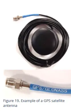
The connector will be labeled as ‘GPS TSYNC’ or ‘GPS CONNECTOR’ (or similar).
L'antenna deve esse stallata sopra a terra è cù una linea diretta di vista à u celu (per coglie i signali di radiu da i satelliti orbitanti).
Exampi lochi sò:
- Superficie muntata à un armariu o postu, puntatu in sopra.
- Incrustu in a faccia superiore di un coperchiu di a camera adattatu, di novu puntatu in sopra.
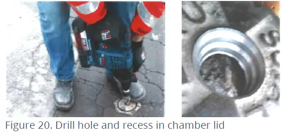
Quandu si mette l'antenna à una tappa di a camera, u coperchiu hè necessariu di avè un recessu perforatu per allughjà u corpu di l'antenna. U recess deve esse abbastanza prufonda per prutege l'antenna da danni. Un exampLe di i passi necessarii seguita, per guida:
- Verificate e dimensioni di l'antenna furnita è u grossu di u coperchio di a camera. Cunsiderate cumu l'antenna serà muntata in a tapa. Se a tapa ùn hè micca abbastanza grossa, una piastra pò esse dumandata à esse stallata à a parte posteriore di a tapa per aumentà a prufundità.
- Perforà a tapa per fà una strada per u cable è u connettore per passà.
- Perforà parzialmente in u coperchiu utilizendu un trapanu più largu per fà un sfondate o recessu adattatu chì u corpu di l'antenna pò inserisce.
 Thread antenna cable through hole, washer, and nut.
- Secure antenna to the lid using a washer and the supplied nut.
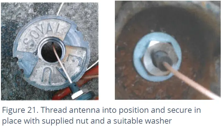
- If required, apply a resin epoxy such as Marine “Goop” to the perimeter of the antenna to help stabilize its position within the lid and to prevent water running onto the antenna cable. Do not cover the top of the antenna body as this may impair reception of satellite signals. Ensure all surfaces are clean and dry before applying the adhesive. Follow the adhesive manufacturer’s instructions.
- Assicuratevi chì u cable di l'antenna ùn sia micca dannatu (per esempiu, da a tapa) durante a stallazione è l'usu.
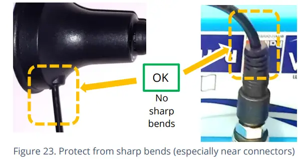
Connect the GPS Antenna to the GPS antenna connector on the logger. Do not over-tighten. For a reliable connection, apply silicon grease and O-ring to the connector prior to fitting, as detailed in section 5.18. Ensure there are no sharp bends in the antenna cable.
Prima di abbandunà u situ, utilizate IDT per fà una prova GPS per cunfirmà a situazione di l'antenna hè OK è chì i segnali satellitari sò stati ricevuti.
ANTENNA (COMUNICAZIONI CELLULARI)
An antenna should be selected to suit the available space in the chamber, allowing some space for it to be re-positioned (if required). Only use HWM-provided antenna with your logger, to ensure the radio interface meets approvals requirements (safety, etc). The Multilog 2 logger uses a metal “FME” style antenna connector.
Prima di cunnette l'antenna, assicuratevi chì u connettore hè seccu è chjaru di terra è detriti; L'umidità intrappulata o i contaminanti ponu influenzallu u rendiment di l'antenna. Pulite se necessariu.
Applicà u grassu di silicone SG M494 à u connettore cum'è necessariu.
The antenna connector has an O-ring included for protection against water and moisture ingress; it acts as a seal. Check that the O-ring is present and undamaged.
Ensure that the connector and O-ring are dry and clear of dirt and debris. Clean carefully if necessary.
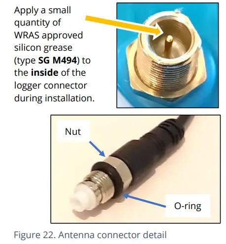
Insert the antenna connector into the logger connection and ensure it is fully home. Tighten the connector correctly; the nut on the antenna should be finger tight, plus 1/4 turn.
Nisuna curva sharp ùn deve esse esistita à l'estremità di u cable, o in u routing di u cable di l'antenna.
Per evità u risicu di danni di schiacciamentu à u cable di l'antenna, verificate chì ùn ci hè micca equipatu sopra. In u listessu modu, i cablaggi chì fissanu u cable in u locu ùn deve esse troppu strettu.
L'antenna ùn deve esse piegata per adattà a stallazione; s'ellu hè troppu grande per a camera, utilizate un tipu più chjucu di antenna appruvata HWM.
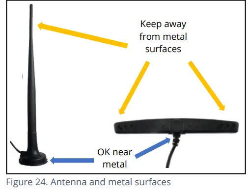
When positioning the antenna, ensure that the radiating end of the antenna does not touch or go close to a metal surface.
L'elementu radiante di l'antenna deve esse idealmente posizionatu in aria libera (senza ostaculi).
Pruvate micca di mette l'antenna in un locu induve pò esse inundatu. Se questu hè inevitabbile, allora u locu induve u risicu hè à u minimu.
Per l'equipaggiu chì hè stallatu in una camara sottu à u livellu di a terra, l'antenna deve esse posta sopra u livellu di a terra, se pussibule. Induve questu ùn hè micca pussibule, postu vicinu à a cima di a camera.
IDT deve esse usatu per verificà chì u logger pò cunnette à a rete cellulare è chì l'antenna hè in a pusizione ottima per u situ.
- Sceglite una antenna adatta per a stallazione è decide nantu à a so pusizione iniziale.
- Determinà a tecnulugia di rete aduprata è poi aduprate i limiti di qualità di signale adattati (consultate a guida d'utilizatore IDT).
- Perform Network Signal tests (with the chamber lid closed) to confirm the logger connects to the mobile network and find the best location of the antenna. Re-position if required.
- Eseguite chjama di prova à cunfirmà u logger pò cumunicà cù u DataGate server via the internet and (if required / available) SMS.
(I dettagli di l'usu di IDT per fà queste teste sò furniti in a guida d'utilizatore di l'app IDT).
Trouble-shoot a test-call failure if required, using the advice in the IDT app user-guide. Further information is given in the HWM Antenna Installation Guide (MAN-072-0001).
Certi cunsiglii generali sò datu quì sottu:
Antenna Monopole
Per a maiò parte di l'installazione, una antenna monopole darà un rendiment accettabile. Considerazioni per l'installazione:
- Rispettate sempre tutte e restrizioni di stallazione cum'è l'avvertimenti in a documentazione furnita.
- L'antenna hà una basa magnetica per esse aduprata per a muntagna.
Per un rendiment ottimali, l'antenna precisa un "pianu di terra" (superficie metallica) à a so basa. - Quandu si stalla l'antenna in grandi camere sotterranee, deve esse posizionata vicinu à a superficia.
- Assicuratevi chì ogni tappa di a camera ùn interferisce micca cù l'antenna o i cavi quandu hè apertu / chjusu.
- Questa antenna hè polarizzata verticalmente, deve esse sempre installata in orientazione verticale.
- Ùn piegate mai l'elementu radiante di l'antenna.
- L'antenna pò ancu esse attaccata à un supportu di installazione muntatu à un postu marcatu esistenti.
- Induve una antenna hè tenuta in u locu da i magneti, assicuratevi chì u pesu di i cavi ùn carichi micca eccessivamente u magnetu in modu di staccallu da u locu installatu.
- Ùn permette micca à alcun equipamentu di appoggià nantu à u connettore di l'antenna, postu chì u dannu di schiacciamentu à u connettore o u cable di l'antenna pò esse risultatu.
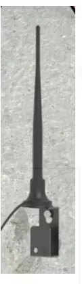
Per altre opzioni di antenna è linee guida d'installazione supplementari, riferite à i documenti dispunibili nantu à u supportu webpagina: https://www.hwmglobal.com/antennas-support/
Risoluzione di un fallimentu di u Test di Call
Ci hè una quantità di mutivi perchè una prova di Call pò falla.
I punti seguenti devenu esse verificati prima di chjamà u supportu HWM per assistenza:
| Prublemu pussibule | Soluzione |
| Network Busy due to excessive traffic. Commonly occurs around schools and at peak travel times. | Riprova a prova dopu à uni pochi di minuti. |
| U signale di a rete ùn hè micca dispunibule in u vostru locu. Ùn tutti i masti Cell portanu trafficu di dati | Relocate the logger to an area that has a data service or change to a different
network provider. |
| Network signal not strong enough.
For 2G and 3G networks, you need a CSQ (reported by the Call test) of at least 8 for reliable communications. For 4G networks, check the RSRP and RSRQ values are suitable, as described in the IDT user guide. |
Trasferite l'antenna se pussibule o pruvate cunfigurazioni alternative d'antenna. |
| Configurazione APN sbagliata. | Check with your network operator that you have the correct settings for your SIM. |
Se cuntinueghja a sperienze prublemi cù a cumunicazione, pudete avè bisognu di verificà a cobertura di a rete in u vostru locu.
SOLUZIONE DI PROBLEMI
Qualchese prublema deve cunsiderà tutte e parte di u sistema (IDT, l'utilizatore, u logger, sensori, a rete cellulare è u servitore).
Cuntrolli generali:
I cuntrolli iniziali da fà durante una visita di u situ includenu:
- Verificate s'è a versione di IDT chì utilizate (app IDT per dispositivi mobili / IDT per PC Windows) supporta e funzioni è i sensori chì utilizate; riferitevi à a sezione 8.
- Verificate chì l'ultima versione di IDT hè stata aduprata.
- Verificate chì u logger chì hè adupratu hà l'ultimu software (IDT offre à aghjurnà se necessariu).
- Verificate a bateria voltage di logger hè bonu (aduprendu u Test Hardware IDT).
- Verificate u cable è i connettori trà i sensori è u logger sò in una cundizione OK, senza danni o ingressi d'acqua.
U logger ùn pare micca esse capace di cumunicà cù IDT:
- Check the communications path from the IDT host device to the logger is complete.(See section 2.8.)
- If using the direct cable connection method with IDT (PC), the logger may have shut down the connection to IDT due to is not being used for several minutes. Re-read the logger settings into IDT. Any previously unsaved settings will have been lost.
- Sè vo aduprate l'app IDT, l'autorizazione per aduprà u cavu pò esse scaduta. Staccate l'estremità USB-A di u cavu di prugrammazione è riattaccatelu uni pochi di secondi dopu. Date l'autorizazione per aduprà u cavu è dopu rileggete i paràmetri di u logger in IDT. Ogni paràmetru micca salvatu prima serà persu.
I dati da u logger ùn appare micca nantu à u servitore:
- Verificate i paràmetri di a carta SIM per accede à a reta di dati mobili.
- Assicuratevi chì u logger utilizeghja a destinazione di dati curretta URL è u numeru di portu per u vostru servitore.
- Verificate i tempi di chjamate sò stati stabiliti.
- Verificate l'antenna hè attaccata è in una cundizione OK.
- Verificate a qualità di u signale è i paràmetri di forza sò adattati. Rilocalizà l'antenna, se necessariu, o pruvate un tipu alternativu di antenna.
- Fate un Test di Chjama è cunfirmà OK.
- Assicuratevi chì u vostru servitore hè cunfiguratu currettamente per riceve è presentà e dati.
MANUTENZIONE, SERVIZIO E REPARAZIONE
Unauthorized servicing will void the warranty and any potential liability for
L'impresa HWM-Water Ltd.
PULIZIA
Nota l'avvertimenti di sicurità chì sò applicabili à a pulizia. L'unità pò esse pulita cù una soluzione di pulizia suave è adamp tela molle. Mantene sempre i connettori senza impurità è umidità.
PARTI SUSTITUIBILI
Antenna
Aduprate solu l'antenna cunsigliata è furnita da HWM.
Per i dettagli di l'opzioni di l'antenna è i numeri di parte per l'ordine, riferite à u ligame seguente: https://www.hwmglobal.com/antennas-support/ (o cunsultate u vostru rappresentante HWM).
Batterie
- Aduprate solu batterie è pezzi cunsigliati è furniti da HWM.
- E batterie sò rimpiazzabili solu da un centru di serviziu appruvatu HWM o da un tecnicu qualificatu pertinenti. Cuntattate u vostru rappresentante HWM per più dettagli se necessariu.
- Batteries can be returned to HWM for disposal. To arrange the return, complete the on-line RMA (Returned Materials Authorisation) form: https://www.hwmglobal.com/hwm-rma/
- Riferite à l'Avvertenze di Sicurezza è l'Informazioni di Approvazione per e linee guida di i requisiti di imballaggio.
carta SIM
- E carte SIM ponu esse rimpiazzate da un centru di serviziu appruvatu da HWM o da un tecnicu furmatu in modu apprupriatu.
- Aduprate solu parti di consumabili cunsigliate è furnite da HWM.
RETURN OF PRODUCT FOR SERVICE O REPAIR
Quandu rinviate u pruduttu per investigazione o riparazione, assicuratevi di seguità l'istruzzioni di u vostru distributore per documentà perchè u pruduttu hè tornatu è furnisce i dati di cuntattu.
Se vultate à HWM, questu pò esse fattu cumpiendu u furmulariu RMA in linea: https://www.hwmglobal.com/hwm-rma/
Prima di a spedizione, mette l'equipaggiu in modu di spedizione (consultate a guida d'utilizatore IDT per l'istruzzioni). Riferite à l'Avvertenze di Sicurezza è l'Informazioni di Approvazione per e linee guida di i requisiti di imballaggio.
Se sporche, assicuratevi chì l'unità hè pulita cù una soluzione di pulizia suave è una spazzola morbida, disinfettata è secca prima di a spedizione.
APPENDIX 1: SYSTEMS AND FEATURES REQUIRING IDT (PC)
Historically, setup of Multilog2 loggers was undertaken using the IDT (PC/Windows) tool. Setup of most Multilog2 logger functions for Pressure and Flow channels and the most commonly used alarm types has recently been introduced to the IDT (mobile app) tool. However, the IDT (mobile app) does not yet support some situations.
The following logger types require IDT (PC) for their entire setup:
- WL/*/*/* Multilog2 logger device (models for use in WITS systems). Refer to the IDT (PC) user-guide for most settings. Additional information for WL series models can be found in the following user-guide: MAN-147-0017 (Supplement for models supporting WITS protocol).
- RDL6*LF/* Multilog (original) logger devices.
E seguenti cumminazzioni di logger/sensore richiedenu IDT (PC) per a cunfigurazione:
- Multilog2 using a SonicSens2 sensor.
- Multilog2 using a SonicSens3 sensor.
- Multilog2 using a RS485/MODBUS sensor.
- Multilog2 using an SDI-12 sensor.
- Multilog2 using a Hydrophone or LNS (Leak-Noise Sensor).
- Multilog2 using a GPS Satellite (for either location or Time-sync).
E seguenti funzioni di u logger richiedenu IDT (PC) per a cunfigurazione:
- Aghjurnamentu di u firmware di u logger o di i sensori attaccati.
- Funzioni di registrazione rapida (Pressione Transitoria, Registrazione di Rete Migliorata).
- Portata (quandu calculata da a velocità di u flussu, a prufundità di u canale, a geometria di u canale).
- Profile Alarma.
- Tamper Alarma.
- GPS functions, including GeoFence Alarm.
APPENDIX 2: COMMUNICATING TO LOGGER VIA SMS
Nota: This facility may not be available on your logger, depending on the SIM card fitted. Some SIM cards or networks or service providers do not have SMS messaging available. (See also section 1.4).
- Applying a ‘Modem Activation Key’ (See Figure 25) to the 10-pin Comms interface for a period of 10 seconds will activate the logger’s cellular communications modem for a period of 5 minutes. This will allow an installer to send SMS (text) messages from a mobile phone and for the logger to respond.
(There is an alternative way to do this using IDT). - Chiude a camera o l'armadiu in modu chì tuttu hè in a so pusizioni finali.
- Using a standard mobile phone, send a text message to the SMS number of the logger (check the logger label), including the international dialing code if needed.
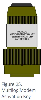
- U messagiu di testu deve leghje TTTT #
Dopu qualchì seconde / minuti (secondu l'operatore di a rete) u logger vi mandarà un missaghju cù dettagli di u so status attuale.
- Exampa risposta da un logger:
TTTT138-002 V01.70CSQ:1010.9VyouridRT hh:mm ss dd-mm-yy…
Per decifrare u missaghju restituitu, fate riferimentu à a tabella sottu:
| Missaghju | Descrizzione |
| TTTT | Original command text without # |
| 138-002 | Logger type number |
| V01.00 | Firmware version in Logger. |
| CSQ: nn | Signal strength nn (nn = 6 to 30) |
| 10.9V | Voltage |
| yourid | Your Logger ID |
| RT hh:mm ss dd-mm-yy | Real Time Clock setting |
| ST hh:mm ss dd-mm-yy | First Time the logger was started |
| LR hh:mm ss dd-mm-yy | Last Time the logger was re-started |
| Ch1 (A) 0029.0 | Channel 1 29.0 units |
| Ch2 (A) 0002.2 | Channel 2 2.2 pulses/sec |
If the CSQ: value in the message is OK, then the installation is complete. The logger will automatically go back to sleep after 10 minutes.
Ci ponu esse ritardi in a reta di SMS, cusì a risposta à u vostru messagiu ùn pò esse immediata. Se ùn avete micca risposta in 10 minuti, riapre a camera è utilizendu u modem diagnosticu mandate un SMS di prova. Se questu passa, allora migliurà u locu di l'antenna è pruvate di novu.
Nota: Some Roaming SIM cards do not accept incoming text messages.
Check with your service provider if you are unsure.
- Sistemi di Conservazione di Fluid 1960 Old Gatesburg Road Suite 150
- State College PA, 16803 800-531-5465
- www.fluidconservation.com
FAQ
Q: Where can I find additional support for Multilog 2?
A: For further assistance not covered in the manual, contact the HWM Technical Support team at +44 (0) 1633 489479 or email cservice@hwm-water.com.
Documenti / Risorse
 |
FCS Multilog2 Multi Channel Data Logger [pdfManuale d'usu ML- - -, PT- - -, EL- - -, Multilog2 Multi Channel Data Logger, Multilog2, Multi Channel Data Logger, Data Logger, Logger |