FCS Multilog2 Multi Channel Data Logger
વિશિષ્ટતાઓ
- ઉત્પાદન નામ: Multilog 2
- ઉપકરણનો પ્રકાર: ડેટા લોગર
- આવરી લેવામાં આવેલ મોડલ્સ: ML/*/*/* PT/*/*/* EL/*/*/* WL/*/*/*
- વધારાના મોડલ્સ: WL series models for WITS systems
- Software Tool: IDT (Installation and Diagnostic Tool)
પરિચય
The “Multilog2” is a multi-purpose data logger device. Several models are available. Please contact your sales representative for help with selection of an appropriate model for your application.
HWM also provides a software tool, known as “IDT” (“Installation and Diagnostic Tool”) for logger setup and test. (See also section 1.6).
MODELS COVERED, DOCUMENTATION AND SUPPORT OF PRODUCT
આ વપરાશકર્તા માર્ગદર્શિકા નીચેના મોડેલોને આવરી લે છે:
મોડલ નંબર ઉપકરણ વર્ણન
| મોડલ નંબર | ઉપકરણ વર્ણન |
| ML/*/*/* | Multilog2 logger device. |
| PT/*/*/* | Pressure Transient2 logger device. |
| EL/*/*/* | Enhanced Network2 logger device. |
| WL/*/*/* | Multilog2 logger device (models for use in WITS systems).
– Additional information for WL series models can be found in the supplementary user guide. |
આ વપરાશકર્તા-માર્ગદર્શિકા આની સાથે મળીને વાંચવી જોઈએ:
| દસ્તાવેજ નંબર | દસ્તાવેજ વર્ણન
Safety Warnings and Approvals Information (for Multilog2). IDT (PC સંસ્કરણ) વપરાશકર્તા-માર્ગદર્શિકા. Multilog2 (Supplement for models supporting WITS protocol) IDT (app for mobile devices) user-guide. |
| MAN-147-0003 | |
| MAN-130-0017 | |
| MAN-147-0017 | |
| MAN-2000-0001 |
આ વપરાશકર્તા-માર્ગદર્શિકા લોગર ઓપરેશન અને ઉત્પાદન કેવી રીતે ઇન્સ્ટોલ કરવું તેની વિગતો પ્રદાન કરે છે. લોગર સાથે ઉપયોગમાં લેવાતા સેન્સર માટે કોઈપણ વપરાશકર્તા-માર્ગદર્શિકાઓ અથવા ડેટાશીટ્સનો પણ સંદર્ભ લો.
તમારા લોગરના સેટઅપની પુષ્ટિ કેવી રીતે કરવી અથવા તેમાં ફેરફાર કેવી રીતે કરવા તે અંગે માર્ગદર્શન માટે IDT વપરાશકર્તા-માર્ગદર્શિકાના સંબંધિત ભાગો વાંચો. આમાં શામેલ છે:
- સેન્સર ચેનલોના સેટઅપ અને ડેટાના રેકોર્ડિંગની વિગતો.
- સર્વર પર માપન ડેટાના વિતરણ માટે લોગર સેટિંગ્સ.
- વધારાની મેસેજિંગ સુવિધાઓ માટે લોગર સેટઅપ, જેમ કે એલાર્મ.
નોંધ: સિસ્ટમમાં સમયાંતરે નવી સુવિધાઓ અને ફેરફારો પ્રકાશિત થાય છે, તેથી તમે આ માર્ગદર્શિકામાં દર્શાવેલ આકૃતિઓ અને સુવિધાઓમાંથી થોડા ફેરફારો જોઈ શકો છો. ઇન્સ્ટોલ કરેલી સુવિધાઓ અને કાર્યક્ષમતા ઉપકરણથી ઉપકરણમાં બદલાઈ શકે છે, તેથી તમારા લોગર ઉપકરણ પર કઈ સુવિધાઓ ઉપલબ્ધ છે તે નક્કી કરવા માટે હંમેશા કોઈપણ સેટઅપ ટૂલના મેનુ અને સ્ક્રીનનો સંદર્ભ લો.
HWM અમારા ગ્રાહક સપોર્ટ દ્વારા લોગર ડિવાઇસ માટે સપોર્ટ પૂરો પાડે છે. webપૃષ્ઠો: https://www.hwmglobal.com/help-and-downloads/
જો તમારી પાસે આ માર્ગદર્શિકા અથવા ઑનલાઇન સહાય દ્વારા આવરી લેવામાં આવતાં ન હોય તેવા કોઈ પ્રશ્નો હોય, તો કૃપા કરીને +44 (0) 1633 489479 પર HWM ટેકનિકલ સપોર્ટ ટીમનો સંપર્ક કરો અથવા ઇમેઇલ કરો cservice@hwm-water.com
સુરક્ષા વિચારણાઓ
આગળ વધતા પહેલા, ઉત્પાદન સાથે પૂરા પાડવામાં આવેલ "સુરક્ષા ચેતવણીઓ અને મંજૂરી માહિતી" દસ્તાવેજમાં આપેલી માહિતી કાળજીપૂર્વક વાંચો અને તેનું પાલન કરો. આ સામાન્ય સલામતી માહિતી પ્રદાન કરે છે.
ભવિષ્યના સંદર્ભ માટે તમામ દસ્તાવેજો રાખો.
Before using this product, make a risk assessment of the installation site and expected work activity. Ensure suitable protective clothing is worn and working practises are followed during installation and any maintenance.
ચેતવણી: જ્યારે આ સાધનસામગ્રીનો ઉપયોગ, ઇન્સ્ટોલ, એડજસ્ટ અથવા સર્વિસ કરવામાં આવે ત્યારે આ સાધનસામગ્રીના બાંધકામ અને સંચાલન અને કોઈપણ ઉપયોગિતા નેટવર્કના જોખમોથી પરિચિત યોગ્ય લાયકાત ધરાવતા કર્મચારીઓ દ્વારા હાથ ધરવામાં આવવું જોઈએ.
ઓપરેટિંગ તાપમાન
ઉપકરણના સ્ટોરેજ અને ઓપરેટિંગ તાપમાન શ્રેણી પર માર્ગદર્શન માટે લોગર ડેટાશીટ અથવા તમારા વેચાણ પ્રતિનિધિનો સંદર્ભ લો. ખાતરી કરો કે એકમ ઇન્સ્ટોલેશન અથવા સેટઅપ પહેલાં ઓપરેટિંગ તાપમાન શ્રેણીમાં છે.
USE OF CELLULAR NETWORKS – IMPORTANT NOTES
SMS ની ઉપલબ્ધતા
Most Multilog2 models include the ability to communicate to a server via use of the cellular data network. This is usually via the regular data network (which gives internet access). Alternatively, the SMS (Short Message Service) messaging can be used; in most cases this will be as a fall-back if the logger is temporarily unable to access the regular data network. If configured for SMS use, the logger uses the available 2G network.
મહત્વપૂર્ણ: 2G (GPRS) સેવાઓ, જે SMS મેસેજિંગ સિસ્ટમ ધરાવે છે, તે વિશ્વભરમાં ધીમે ધીમે બંધ થઈ રહી છે. એકવાર 2G બંધ થઈ જાય પછી, લોગરમાં ઉપલબ્ધ SMS સેવાઓ હવે કાર્ય કરી શકશે નહીં. લોગર સેટિંગ્સમાં નિષ્ક્રિય ન થાય ત્યાં સુધી, લોગર પ્રયાસ કરવાનું ચાલુ રાખશે, બેટરી પાવર બગાડશે. તેથી, SMS બેકઅપ સેવા અથવા SMS ઉપયોગની જરૂર હોય તેવી કોઈપણ અન્ય સુવિધાનો ઉપયોગ કરવા માટે લોગર સેટ કરતા પહેલા તમારા સેલ્યુલર નેટવર્ક ઓપરેટર સાથે તેમની સ્વિચ ઓફ તારીખ માટે તપાસ કરો.
To deactivate the use of the SMS system, any related SMS settings must be removed (switched off or deleted). Refer to the IDT User Guide for details of SMS settings.
Any modified settings must be saved to the logger.
નોંધ: SMS સેવાઓના ઉપયોગ માટે, લોગર અને સેલ્યુલર નેટવર્ક પ્રદાતા બંનેએ SMS ને સપોર્ટ કરવો આવશ્યક છે. વધુમાં, લોગરની અંદર ફીટ કરેલ SIM કાર્ડ SMS ના ઉપયોગને સપોર્ટ કરતું હોવું જોઈએ. (જો જરૂરી હોય તો તમારા SIM સપ્લાયર સાથે તપાસ કરો).
SMS નો ઉપયોગ કરતી વખતે લોગર ઓળખ
સેલ્યુલર ડેટા નેટવર્કનો ઉપયોગ કરતી વખતે, સંદેશમાં રહેલા ડેટા સાથે લોગર ઓળખનો સમાવેશ થાય છે. જોકે, SMS સિસ્ટમનો ઉપયોગ કરતી વખતે, ઓળખ એ કોલિંગ નંબર (SIM કાર્ડમાંથી) હોય છે. આમ, કોઈપણ SMS સેવાઓનો ઉપયોગ કરતી વખતે, આ બે નંબરો (લોગર ટેલિફોન નંબર અને SIM ટેલિફોન નંબરનું IDT સેટિંગ) મેળ ખાતા હોવા જોઈએ.
VIEWઆઈએનજી ડેટા
થી view લોગર ડેટા રિમોટલી, એ viewing ટૂલ (webસાઇટ) નો ઉપયોગ થાય છે. વિવિધ webસાઇટ્સ ઉપલબ્ધ છે. દરેક webસાઇટ લોગર ઇન્સ્ટોલેશન સાઇટ્સ સાથે સંકળાયેલ ડેટા રજૂ કરે છે. ની પસંદગી webસાઇટ ઉપયોગમાં લેવાતા સેન્સરના પ્રકાર અને તેમની એપ્લિકેશન પર આધારિત રહેશે.
તમારા લોગરનો ડેટા પણ હોઈ શકે છે viewસાઇટની મુલાકાત દરમિયાન IDT નો ઉપયોગ કરીને સ્થાનિક રીતે ed.
તમારા માટે ઉપલબ્ધ તાલીમ સામગ્રીનો સંદર્ભ લો viewવધુ માહિતી માટે ing ટૂલ અને IDT વપરાશકર્તા-માર્ગદર્શિકા પણ જુઓ.
IDT – SOFTWARE TOOL (FOR LOGGER PROGRAMMING AND TESTS)
એક સોફ્ટવેર ટૂલ, જેને "IDT" (ઇન્સ્ટોલેશન એન્ડ ડાયગ્નોસ્ટિક ટૂલ) તરીકે ઓળખવામાં આવે છે, તે લોગર સેટઅપને તપાસવા અથવા એડજસ્ટમેન્ટ કરવા માટે અને સાઇટ પર લોગર ઓપરેશનના પરીક્ષણ માટે પણ ઉપલબ્ધ છે.
કયું સંસ્કરણ વાપરવું તે પસંદ કરી રહ્યા છીએ
IDT સોફ્ટવેર ટૂલ લોગરને યુઝર-ઇન્ટરફેસ પૂરો પાડે છે. તેનો ઉપયોગ લોગર સેટિંગ્સ તપાસવા અથવા તેમાં ગોઠવણો કરવા અને તેની ઇન્સ્ટોલ કરેલી સાઇટમાં લોગર કામગીરીનું પરીક્ષણ કરવા માટે થઈ શકે છે. IDT આ કાર્યો કરી શકે તે પહેલાં, તેણે લોગર સાથે 'કનેક્ટ' થવું પડશે; આનો સીધો અર્થ એ છે કે બે અંતિમ ઉપકરણો (લોગર સોફ્ટવેર અને IDT સોફ્ટવેર) કાર્યકારી સંચાર માર્ગ પર એકબીજા સાથે વાતચીત કરવા સક્ષમ છે.
IDT ત્રણ વર્ઝનમાં ઉપલબ્ધ છે:
- વિન્ડોઝ-ઓપરેટિંગ સિસ્ટમ ધરાવતા પીસી માટે IDT.
- એન્ડ્રોઇડ ઓપરેટિંગ સિસ્ટમ ધરાવતા મોબાઇલ ઉપકરણો (ફોન અને ટેબ્લેટ) માટે IDT.
- (એપલ) iOS સિસ્ટમ ધરાવતા મોબાઇલ ઉપકરણો (ફોન અને ટેબ્લેટ) માટે IDT.
પછીના બેને 'IDT એપ' તરીકે ઓળખવામાં આવે છે, જ્યારે પહેલાને 'IDT (PC)' અથવા 'IDT (Windows)' તરીકે ઓળખવામાં આવે છે.
It is recommended to install and use the IDT app version whenever possible; it covers most types of HWM loggers. There are, however, a small number of situations where loggers or logger/sensor combinations that (at the time of writing) require the use of the IDT (PC) tool. Refer to section 8 for further details of which sensors or features require IDT (PC), as applicable to the loggers listed in section 1.1.
IDT (PC સંસ્કરણ)
લોગર સાથે વાતચીત કરવા માટે તમારા PCને કેવી રીતે તૈયાર કરવું તેની વિગતો માટે IDT (PC સંસ્કરણ) વપરાશકર્તા માર્ગદર્શિકા (MAN-130-0017) નો સંદર્ભ લો. વપરાશકર્તા-માર્ગદર્શિકા વિવિધ લોગર સેટિંગ્સ સાથે IDT નો ઉપયોગ કેવી રીતે કરવો તેની વિગતો પણ આપે છે.
IDT APP (MOBILE DEVICE VERSION)
Refer to the IDT app User-Guide (MAN-2000-0001) for details of how to prepare your mobile device (Android-based Tablet) for communicating with the logger. The user-guide also gives details of how to use the IDT app with various logger settings.
ઓવરVIEW
LOGGER DEVICE OVERVIEW
ભૌતિક લક્ષણો અને કનેક્ટર ઓળખ
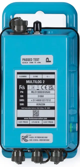
The Multilog2 logger family is flexible in design and can be built to suit a variety of uses. It has a metal enclosure and is of a waterproof construction, using a seal to keep out water.
ભૂતપૂર્વample આકૃતિ 1 માં બતાવેલ છે.
The logger is powered by a non-rechargeable Lithium battery. The life of the battery can vary with its orientation; refer to Figure 1 for the orientation that will give best battery life.
The top of the logger includes a handle, used for carrying the unit. It also provides a convenient way of hanging the unit in its correct orientation using wall-mounted brackets or other fixing methods.
લોગર પર વિવિધ લેબલ્સ હાજર છે. આમાં શામેલ છે:
- The nameplate label, which includes the logger part-number, its serial number, and an ‘SMS number’ (an identifier for the logger, in the form of a telephone number).
- ઇન્ટરફેસ ઓળખ લેબલ્સ.
The logger has waterproof electrical connectors for attaching sensors and the antenna. These can be present on two surfaces (top and bottom). The interfaces installed, and their position, will vary between model-number supplied. Follow the labels to identify interfaces.
A pressure interface may also employ a built-in pressure transducer with a quick-release connector. This is for direct connection to a pipe (or hose).
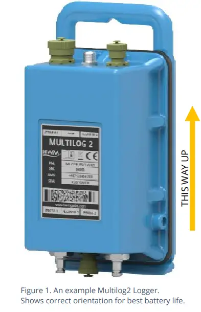
બાહ્ય બેટરી (વિકલ્પ)
Most Multilog2 models have a connector that allows an External Battery to be connected. These provide the logger with additional power capacity.
ભૂતપૂર્વample આકૃતિ 2 માં બતાવેલ છે.
વિવિધ બેટરી ક્ષમતાઓ ઉપલબ્ધ છે.
Always use HWM supplied batteries to ensure compatibility and safety. Ensure the cable supplied with the battery is suitable for the external power connector fitted to your logger. (6-pin and 10-pin connector versions are available. See also section 2.7).
(બાહ્ય બેટરીનો ઉપયોગ જરૂરી હોય તેવી પરિસ્થિતિઓમાં, તમારા HWM પ્રતિનિધિની સલાહ લો).
લોગર ઓપરેશન
- The logger software is designed to minimize battery use and thereby prolong the expected battery life. However, battery life is also affected by user-programmablesettings. The user is advised to set the logger tasks and sampબેટરી પાવરને અસરકારક રીતે મેનેજ કરવા માટે ઇચ્છિત ઉપયોગની ન્યૂનતમ આવશ્યકતાઓ માટે આવર્તન.
- જ્યાં સપ્લાય કરવામાં આવે છે, બાહ્ય બેટરી પાવરનો ઉપયોગ લોગરની બેટરી લાઇફ વધારવા અથવા હોસ્ટ સર્વર સાથે વધુ વારંવાર સંચાર કરવા માટે થાય છે.
- લોગરને સામાન્ય રીતે ફેક્ટરીમાંથી નિષ્ક્રિય સ્થિતિમાં મોકલવામાં આવે છે (જેને તરીકે ઓળખવામાં આવે છે
'શિપિંગ મોડ', અથવા 'સ્લીપ મોડ') બેટરીના જીવનને બચાવવા માટે. - When activated (see section 3), the logger will initially go into the state of “Waiting” (for a short time). Then it will go into the state of “Recording” and begin repetitive logging of measurements from the various sensors fitted to the unit, according to its configuration and settings.
- લોગર બે સમયગાળાનો ઉપયોગ કરીને કાર્ય કરે છે, જેને "s" તરીકે ઓળખવામાં આવે છેampલે પીરિયડ" અને "લોગ પીરિયડ". તે એસ કરશેamps પર સેન્સર્સ લે છેampકામચલાઉ માપન બનાવવા માટે le દરampલેસ; આ પુનરાવર્તિત પૃષ્ઠભૂમિ કાર્ય છે. અનેક માપ લીધા પછી એસampલેસ, લોગ રેટ પર લોગ થયેલ (સાચવાયેલ) ડેટાપોઈન્ટ બનાવવા માટે કેટલાક આંકડાકીય કાર્યો વૈકલ્પિક રીતે લાગુ કરી શકાય છે; આ રેકોર્ડ કરેલ (લોગ કરેલ) માપન બનાવે છે અને મેમરીના ક્ષેત્રમાં સાચવવામાં આવે છે જેને "પ્રાથમિક રેકોર્ડિંગ" તરીકે ઓળખવામાં આવે છે. લોગ પીરિયડ હંમેશા s નો ગુણાંક હોય છેampસમયગાળો.
- જો લૉગર પાસે સુવિધા સક્ષમ હોય, તો તેને ક્યારેક-ક્યારેક વધારાના ડેટાને “સેકન્ડરી રેકોર્ડિંગ” મેમરી એરિયામાં સાચવવા માટે પણ સેટ કરી શકાય છે (વિભાગ 2.4 જુઓ), (દા.ત., ડેટાampઉચ્ચ આવર્તન પર દોરી જાય છે, જેમ કે “s નો ઉપયોગ કરીનેampલે પિરિયડ”ને બદલે “લોગ પિરિયડ”).
નોંધ: આ તમામ સપ્લાય કરેલ એકમો પર ઉપલબ્ધ નથી અને ઓર્ડર આપતા પહેલા તમારા વેચાણ પ્રતિનિધિ દ્વારા ગોઠવાયેલ હોવું આવશ્યક છે; તે એકમની અપેક્ષિત બેટરી જીવનને લગતી અસરો ધરાવે છે.
The logger will also have daily tasks at set times, such as uploading its unsent data over the internet. When sending data, the logger waits to receive confirmation from the server that the data was received without error; If confirmation is not received, it will re-send the data at the next call-in time.
લોગરને ચોક્કસ પેટર્ન અથવા શરતો માટે ડેટા મોનિટર કરવા માટે પ્રોગ્રામ કરી શકાય છે અને જો તે મેચ શોધે તો તે સંદેશ મોકલી શકે છે. સામાન્ય રીતે, આનો ઉપયોગ એવી સ્થિતિ સેટ કરવા માટે થાય છે જે "એલાર્મ" નો સંકેત હોઈ શકે. સંદેશ ક્યાં તો સર્વર (સામાન્ય ગંતવ્ય) અથવા અન્ય ઉપકરણ પર મોકલી શકાય છે.
ઉન્નત લૉગિંગ (વિકલ્પો)
Section 2.3 gave a description of logger operation that is available as standard on most Multilog2 logger models; The logger normally sampસેટ પર લેસ ડેટાample પિરિયડ, અને સેટ લોગ પિરિયડ પર ડેટાપોઇન્ટ્સ રેકોર્ડ કરે છે. જો કે, અમુક મોડેલો સામાન્ય કરતાં વધુ પર વધારાના રેકોર્ડિંગ્સ (લોગ કરેલા ડેટાના) બનાવવા માટે વિકલ્પો પ્રદાન કરે છે.ampલિંગ દરો. વધારાનો ડેટા "સેકન્ડરી રેકોર્ડિંગ" મેમરી એરિયામાં રેકોર્ડ કરવામાં આવે છે.
These features are sometimes referred to as “Enhanced Network” logging and “Pressure Transient” logging; Collectively they are referred to as “Fast Logging”. The ‘Enhanced Network’ and ‘Pressure Transient’ loggers (both being based on the Multilog2 design), have the named option available as standard.
નોંધ: The feature can only be installed by the factory at the time of build. The options must therefore be specified at the time of ordering, along with the required maximum sampલિંગ દર.
વધારાના એસampલિંગ પાવર વપરાશ માટે અસરો ધરાવે છે અને આવશ્યક સેવા જીવનને પહોંચી વળવા માટે બાહ્ય બેટરીના ઉપયોગની જરૂર પડી શકે છે.
લોગર સેટઅપ દરમિયાન લોગરની ઝડપી-લોગિંગ સુવિધાઓને અક્ષમ કરી શકાય છે. જ્યાં સક્ષમ હોય, લોગર પાસે મેમરી પૂર્ણ થવાની સાથે કામ કરવા માટે બે વ્યૂહરચના છે. કાં તો ફાસ્ટ લોગીંગ બંધ થઈ જશે, અથવા જુનો ડેટા ઓવર-રાઈટ થઈ શકે છે. સેટઅપ દરમિયાન તમને જરૂરી પસંદગી કરો.
તમામ પ્રકારના સેન્સર ઉચ્ચ s પર કામ કરવા સક્ષમ નથીampલિંગ ફ્રીક્વન્સીઝ. આ સુવિધા સામાન્ય રીતે એનાલોગ સેન્સર સાથે કામ કરવા માટે સેટ કરવામાં આવે છે, જેમ કે પ્રેશર ટ્રાન્સડ્યુસર.
પાણી પુરવઠા નેટવર્ક પર દબાણની વધઘટને મોનિટર કરવા માટે ઝડપી લોગીંગનો વારંવાર ઉપયોગ થાય છે.
For Multilog2, ‘Enhanced Network’ logging and ‘Pressure Transient’ logging are mutually exclusive settings (only one can be used). Each has a different operation.
ઉન્નત નેટવર્ક લોગીંગ:
- આ વિકલ્પ અમુક ઇવેન્ટ્સને ગૌણ રેકોર્ડિંગ બનાવવાની મંજૂરી આપે છે.
- રેકોર્ડિંગ પૃષ્ઠભૂમિ પર કરવામાં આવશેampલિંગ દર.
- રેકોર્ડિંગ એક ચેનલ હોઈ શકે છે અથવા વધારાની ચેનલો શામેલ હોઈ શકે છે (જો સેન્સર ઝડપ સાથે સામનો કરી શકે છે).
- મહત્તમ એસampલિંગ દર 1Hz ની આવર્તન સુધી મર્યાદિત છે.
દબાણ ક્ષણિક લોગિંગ:
- આ વિકલ્પ અમુક ઇવેન્ટ્સને ગૌણ રેકોર્ડિંગ બનાવવાની મંજૂરી આપે છે.
સંગ્રહિત કરવા માટે જરૂરી ડેટાની માત્રાને કારણે લોગર પાસે વધારાની મેમરી હોય છે. - આ રીતે રેકોર્ડિંગ કરવામાં આવશેamp1Hz નો લિંગ રેટ અથવા ઉચ્ચ ફ્રીક્વન્સીઝમાંથી એક, 25Hz સુધી.
- On Multilog2, up to two channels can be used. Each of these must be for a pressure sensor. The sensors must be allocated to channel 1, or channels 1 & 2.
રેકોર્ડિંગ ચોક્કસ સમયે અથવા વિવિધ એલાર્મ ઇવેન્ટ્સ અથવા સ્ટેટસ ઇનપુટમાં ફેરફાર (એટલે કે, બાહ્ય સાધનોમાંથી સ્વિચ આઉટપુટ દ્વારા ટ્રિગર થાય છે)ના પ્રતિભાવમાં સેટ કરી શકાય છે.
સર્વર એકીકરણ - સ્ટોરિંગ અને VIEWઆઈએનજી ડેટા
The Multilog2 logger includes an interface (referred to as a modem) that provides access to the internet via the cellular mobile communications network. A SIM card is used to give access of the network.
માપન ડેટા શરૂઆતમાં લોગરમાં સંગ્રહિત થાય છે, આગલા કૉલ-ઇન સમય સુધી. ત્યારબાદ એનક્રિપ્ટેડ ફોર્મેટનો ઉપયોગ કરીને ડેટા સર્વર પર અપલોડ કરી શકાય છે. સામાન્ય રીતે, ડેટા મેળવવા અને સ્ટોર કરવા માટે વપરાતું સર્વર HWM Da હશેtaGate સર્વર, જો કે અન્ય સર્વરનો ઉપયોગ HWM સોફ્ટવેર સાથે જોડાણમાં થઈ શકે છે.
લોગર ડેટા હોઈ શકે છે viewed નો ઉપયોગ કરીને a viewing પોર્ટલ કે જે સર્વર પર સંગ્રહિત ડેટાની ઍક્સેસ ધરાવે છે. (તમારો ડેટા કેવી રીતે છે તેની વિગતો માટે સંબંધિત વપરાશકર્તા માર્ગદર્શિકાનો સંદર્ભ લો viewer નો ઉપયોગ કરી શકાય છે view લોગર ડેટા).
નોંધ: Multilog2 loggers supporting WITS protocol behave differently to the above.
These loggers do not use DataGate but communicate with a WITS Master Station. The data can be viewed only by use of the WITS system.
DATAGATE સર્વર / ડેટા VIEWઆઈએનજી પોર્ટલ્સ
જ્યારે HWM ના ડા સાથે સંકલિતtaGate સર્વર, લોગરના માપન ડેટાને કેન્દ્રિય રીતે સંગ્રહિત કરી શકાય છે અને a દ્વારા વપરાશકર્તાઓને ઉપલબ્ધ કરાવી શકાય છે viewing પોર્ટલ (webસાઇટ). ડેટા સ્ટોરેજ સર્વર એક યુનિટમાંથી અથવા લોગર્સના સમગ્ર કાફલામાંથી ડેટાની રસીદ અને સંગ્રહને હેન્ડલ કરી શકે છે.
Viewપ્રાથમિક રેકોર્ડિંગ્સ:
તમારા લોગર(ઓ)નો ડેટા હોઈ શકે છે viewપ્રમાણભૂત ઉપયોગ કરીને યોગ્ય વપરાશકર્તા ખાતા (અને પાસવર્ડ) સાથે, આમ કરવા માટે અધિકૃત કોઈપણ દ્વારા દૂરસ્થ / ગ્રાફિકલી રીતે સંપાદિત. web-બ્રાઉઝર.
HWM પાસે પસંદગી છે webસાઇટ્સ જેનો ઉપયોગ કરી શકાય છે view લોગર ડેટા. ની શ્રેષ્ઠ પસંદગી webસાઇટ લોગર સાથે ઉપયોગમાં લેવાતા સેન્સરના પ્રકાર પર આધારિત છે.
A webસામાન્ય ડેટા સાથેની સાઇટ viewer can show data graphically, but only for one logger at a time, installed on one site.
A webસાઇટ કે જે લોગર્સનો કાફલો બતાવી શકે છે, જેમાં દરેક એક જ પ્રકારનું સેન્સર ધરાવે છે, ઘણી વખત ઉપયોગી પૂરક માહિતી સાથે (દા.ત., લોગર સ્થાનો દર્શાવતો નકશો) વપરાશકર્તાને વધુ અર્થપૂર્ણ રીતે ડેટા રજૂ કરી શકે છે. આમ, એ webસાઇટ એક સમયે ઘણી સાઇટ્સની વર્તમાન સ્થિતિનું ચિત્ર આપી શકે છે.
જેની વિગતો માટે IDT વપરાશકર્તા માર્ગદર્શિકા અથવા સેન્સર વપરાશકર્તા-માર્ગદર્શિકાનો સંદર્ભ લો viewing પોર્ટલ વાપરવા માટે સૌથી યોગ્ય છે. વૈકલ્પિક રીતે, તમારા HWM પ્રતિનિધિ સાથે આ મુદ્દાની ચર્ચા કરો.
આ ડાtaGate સર્વર લોગર તરફથી મળેલા કોઈપણ એલાર્મને તે બધા વપરાશકર્તાઓને ફોરવર્ડ કરી શકે છે જેમણે તેમને સબ્સ્ક્રાઇબ કર્યું છે; તેથી એક લોગર એલાર્મ સંદેશ બહુવિધ Da માં વિતરિત કરી શકાય છેtaGવપરાશકર્તાઓ ખાય છે.
DataGate નો ઉપયોગ અન્ય સર્વર્સ પર લોગર ડેટા નિકાસ કરવા માટે (તમારા વેચાણ પ્રતિનિધિ સાથેની ગોઠવણ દ્વારા) પણ થઈ શકે છે.
સર્વર અને ના કેટલાક વહીવટી સેટઅપ viewing પોર્ટલ સામાન્ય રીતે લોગર ડેટાને યોગ્ય રીતે પ્રાપ્ત કરવા, સંગ્રહિત કરવા અને પ્રસ્તુત કરવા માટે જરૂરી છે. (ડાનું સેટઅપ અને ઉપયોગtaGate સિસ્ટમ (અથવા કોઈપણ અન્ય સર્વર) આ વપરાશકર્તા માર્ગદર્શિકા દ્વારા આવરી લેવામાં આવતી નથી).
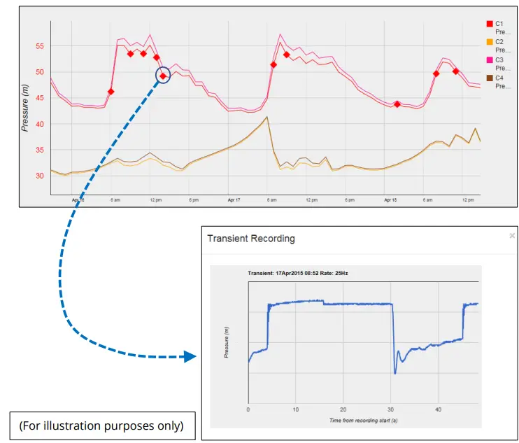
Viewમાધ્યમિક રેકોર્ડિંગ્સ:
ફાસ્ટ લોગીંગ સમાવિષ્ટ સાથે લોગર મોડલ ધરાવતી સાઇટ્સ માટે, ગૌણ રેકોર્ડીંગ્સ કરવામાં આવ્યા હશે. આ સર્વર પર પણ સંગ્રહિત છે.
તમારો ડેટા viewer will have a means of displaying secondary recordings.
It may, for example, જ્યાં ઝડપી ડેટા ઉપલબ્ધ છે તે બિંદુને દર્શાવવા માટે મુખ્ય ટ્રેસ પર માર્કર બતાવો (દા.ત., જ્યાં ક્ષણિક થયું). ક્લોઝ-અપ આપવા માટે માર્કર પર ક્લિક કરો view ક્ષણિક ના.
Viewing location fix (GPS track):
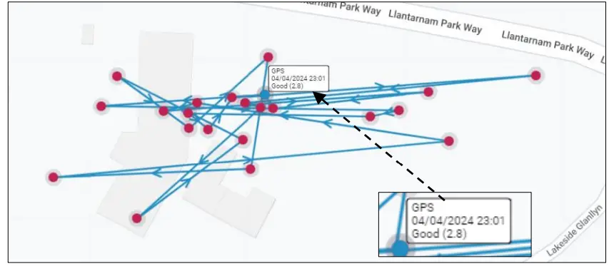
For logger models that include GPS position fix capability, the server will provide a facility to track the location history of the logger. Details of the GPS location fix can be found, typically by selecting one of the shown points. The quality of the location fix will be shown as a number. (This is known as a DOP value. Refer to the table below).
| મૂલ્ય | ગ્રેડ | વર્ણન |
| <2 | ઉત્તમ
/ ideal |
Excellent confidence in location fix accuracy. |
| 2-5 | સારું | Good confidence in location accuracy / reliable result. |
| 5-10 | મધ્યમ | Moderate confidence in location accuracy. A more open view of the sky or acquisition period may improve. |
| 10-20 | ફેર | Low confidence level in location accuracy. Indicates a very rough estimate of location. |
| >20 | ગરીબ | Poor confidence of accuracy of location. The measurement should be discarded. |
સ્થાપન એસેસરીઝ
વિવિધ ઇન્સ્ટોલેશન પરિસ્થિતિઓને અનુરૂપ એસેસરીઝ (એન્ટેના અને યુનિટને માઉન્ટ કરવા માટે કૌંસ) ઉપલબ્ધ છે; તમારા HWM પ્રતિનિધિ સાથે ઉપલબ્ધતાની ચર્ચા કરો.
COMMUNICATIONS INTERFACES AND PROGRAMMING CABLES
To communicate with the Multilog2 logger, a programming cable is required. There are two connector options available in the logger family for making this connection (10-pin or 6-pin); only one of these alternatives will be fitted. Use a programming cable that matches the connector type on the logger.
On Multilog2, the connectors used for communications are frequently shared; they also include the connections required for fitting an external battery (see section 2.2). Because of space limitations, the label may not indicate this (e.g., It may simply be labeled “COMMS”).
A typical connector used for communications and its matching communications cable is shown in Figure 3.
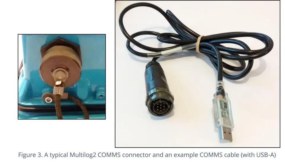
The connector of the communications cable will only include the pins required for communications purposes.
To use the communications cable, temporarily remove any existing connector, and re-connect it when finished. Alternatively, an adaptor (Y-cable) can be inserted to be able to support the logger using both functions together.
Attach the Comms cable to the logger, and then complete the connection to the IDT host using one of the methods described in section 2.8.
Examples of suitable programming cables are given below:
- 10-pin : COM AEUSB (USB to RS232 comms cable).
- CABA2075 (direct USB comms cable).
- 6-pin : CABA8585 (direct USB comms cable).
COMPLETING THE COMMUNICATIONS PATH
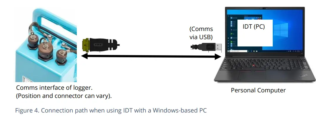
For IDT to communicate with the logger, first select the appropriate cable and connect it to the COMMS connector of the logger, as described in section 2.7. The USB-A end of the programming cable should be used to connect to the IDT host by using one of the following methods:
IDT – USED WITH A PC (& WINDOWS).
ઉપયોગ કરતા પહેલા, પીસીમાં IDT (PC વર્ઝન) પ્રોગ્રામિંગ ટૂલ ઇન્સ્ટોલ કરેલું હોવું જોઈએ.
USB-A છેડો સીધો PC ના USB-A પોર્ટમાં પ્લગ થયેલ હોવો જોઈએ (અથવા યોગ્ય એડેપ્ટર દ્વારા USB-B અથવા USB-C પોર્ટ સાથે). આકૃતિ 4 નો સંદર્ભ લો.
IDT APP – USED WITH A TABLET (ANDROID) / USB OPTION
Certain Android-based Tablet devices (which must have an available USB port) are able to use this method. (For latest information about known compatible devices, contact your HWM representative).
ઉપયોગ કરતા પહેલા, મોબાઇલ ઉપકરણમાં IDT એપ્લિકેશન સોફ્ટવેર ઇન્સ્ટોલ કરેલું હોવું જોઈએ.
The USB-A end should be plugged directly into a USB-A port of the tablet (or to a USB-B or USB-C port via a suitable adaptor). Refer to Figure 5.
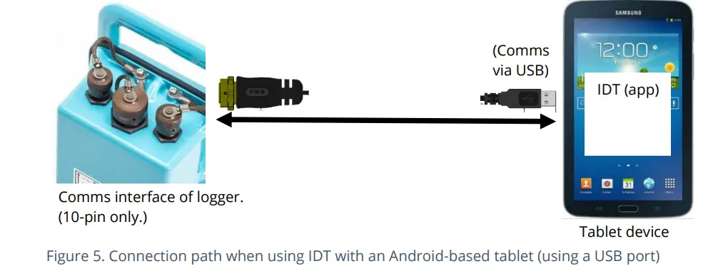
This connection method is only compatible with a 10-pin logger connector and using the COM AEUSEB (USB to RS232) comms cable, or CABA2080 (USB to RS232) Y-Cable.
IDT APP – USED WITH A MOBILE PHONE OR TABLET / BLUETOOTH OPTION
ચોક્કસ મોબાઇલ ફોન અથવા ટેબ્લેટ ઉપકરણો (જે Android અથવા iOS-આધારિત હોવા જોઈએ અને બ્લૂટૂથ રેડિયોને સપોર્ટ કરતા હોવા જોઈએ) આ પદ્ધતિનો ઉપયોગ કરી શકે છે. (જાણીતા સુસંગત ઉપકરણો વિશે નવીનતમ માહિતી માટે, તમારા HWM પ્રતિનિધિનો સંપર્ક કરો).
ઉપયોગ કરતા પહેલા, મોબાઇલ ઉપકરણમાં IDT એપ્લિકેશન સોફ્ટવેર ઇન્સ્ટોલ કરેલું હોવું જોઈએ.
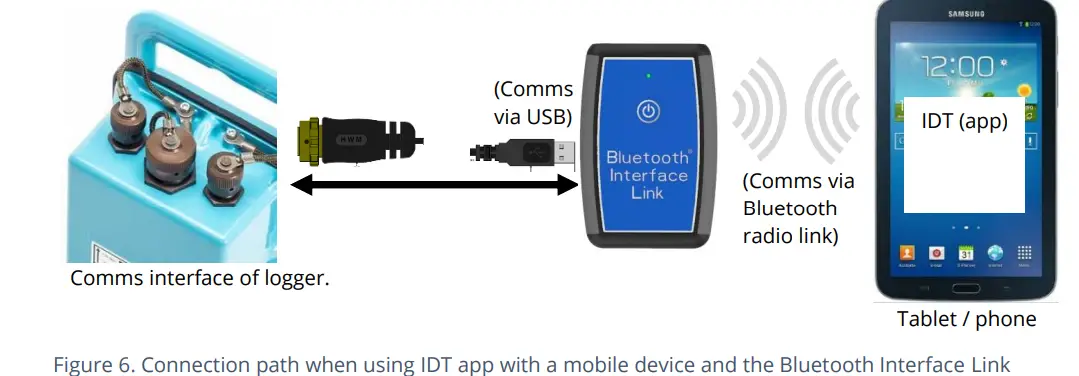
The connection path (refer to Figure 6) makes use of a communications adapter known as the HWM ‘Bluetooth Interface Link’. Connect the logger end of the communications cable to the logger. Then the USB-A end of the communications cable should be plugged into the USB-A port of the Bluetooth Interface Link unit. The device should be turned on during use. The IDT app is required to be paired to the Bluetooth Interface Link unit prior to communication with the logger. The Bluetooth Interface Link handles protocol translations and flow control of messages between the logger
(via the comms cable) and the radio link.
લોગર અને કોમ્યુનિકેશન્સ લિંકને સક્રિય કરી રહ્યા છીએ
કોમ્યુનિકેશન ઇન્ટરફેસ હંમેશા પ્રવૃત્તિ માટે મોનિટર કરવામાં આવે છે અને લોગર સામાન્ય રીતે પ્રતિસાદ આપશે, સિવાય કે તે સેલ્યુલર નેટવર્ક સાથે વાતચીત કરવામાં વ્યસ્ત હોય.
લોગર સક્રિયકરણ પ્રક્રિયા (પ્રથમ વખત ઉપયોગ માટે)
જ્યારે ફેક્ટરીમાંથી મોકલવામાં આવે છે, ત્યારે યુનિટ 'શિપિંગ મોડ'માં હોય છે (નિષ્ક્રિય; લોગિંગ અથવા કૉલ ઇન નથી). આ મોડ શિપિંગ અથવા લાંબા ગાળાના સ્ટોરેજ માટે યોગ્ય છે. લોગરનો ઉપયોગ કરવા માટે, તેને પહેલા સક્રિય કરવું આવશ્યક છે.
આ કરવાની પ્રક્રિયા લોગિંગ ફરીથી સક્રિયકરણ માટે લોગર સેટિંગ પર આધાર રાખે છે. વિવિધ સેટિંગ વિકલ્પો ઉપલબ્ધ છે (નિર્દિષ્ટ સમય, બાહ્ય બેટરીના જોડાણ પર, ચુંબકીય સ્વીચના સક્રિયકરણ પર, 'તાત્કાલિક').
Most loggers are set to start ‘immediately’ upon having their settings read by IDT and then saved back to the unit.
Once activated, the logger will initially go into the state of ‘Waiting’ (for a short time). Then it will enter a status of ‘recording’, where it is executing its repetitive logging functions.
આ પદ્ધતિ IDT ના કયા સંસ્કરણનો ઉપયોગ થઈ રહ્યો છે તેના પર આધાર રાખે છે:
- For IDT (PC), the user can do this manually (even if no program changes are required). (Refer to the IDT user-guide for the steps required to read the logger program and then to save it back to the unit using the ‘Setup Device’ button).
- IDT એપ માટે, વપરાશકર્તા સ્ટાર્ટ ડિવાઇસ બટન દ્વારા મેન્યુઅલી પણ આ કરી શકે છે. વધુમાં, જ્યારે પણ વપરાશકર્તા એપમાંથી લોગરનું નિયંત્રિત ડિસ્કનેક્શન કરશે ત્યારે એપ સંભવિત સમસ્યાઓ માટે તપાસ કરશે, જેમાં એવા લોગર માટે તપાસનો સમાવેશ થાય છે જે હજુ સુધી સક્રિય / રેકોર્ડિંગ નથી.
સાઇટ છોડતા પહેલા, ખાતરી કરો કે લોગર લોગિંગ, કોલ-ઇન કાર્યો માટે યોગ્ય રીતે સેટ થયેલ છે અને તે 'રેકોર્ડિંગ' (લોગિંગ) ની સ્થિતિમાં છે. આ મુદ્દાઓ કેવી રીતે તપાસવા તે અંગે માર્ગદર્શન માટે IDT વપરાશકર્તા-માર્ગદર્શિકાનો સંદર્ભ લો.
INTERFACES AND SENSOR TYPES (SUMMARY)
નોંધ: ચોક્કસ ઈન્ટરફેસ અથવા કાર્યો માટે આધાર અલગ અલગ હોય છે અને તે પૂરા પાડવામાં આવેલ મોડેલ પર આધારિત હોય છે.
સેન્સર વિવિધ ભૌતિક પરિમાણો માટે માહિતી પ્રદાન કરે છે, અને આ માહિતી યોગ્ય ઇલેક્ટ્રિકલ ઇન્ટરફેસ દ્વારા લોગરને ટ્રાન્સફર કરવામાં આવે છે.
દરેક ઈન્ટરફેસમાં માપન શરૂ કરવા અને મેળવેલા આંકડાકીય ડેટાનું યોગ્ય અર્થઘટન કરવા માટે લોગર સેટિંગ્સ સંકળાયેલ છે. IDT નો ઉપયોગ સેટિંગ્સ મેનેજ કરવા માટે થાય છે.
Wired connections are made to the logger via a connector mounted through the logger case. Various sizes are available and can contain either pins or sockets. Some examples are shown in Figure 9 and Figure 8. A dust-cap is available as an option to keep unused connectors free of water and debris (see Figure 7).
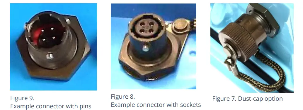
Some connectors are single-purpose in nature (e.g., For connection of a single sensor). However, other connectors may be multi-purpose (e.g., Having both a connection for a programming cable and also for the supply of power from an additional battery).
Where a connector is multi-purpose, a Y-adapter cable may be required to split out the various functions.
For water pressure measurement, the electrical connection to the sensor may be made via a standard electrical connector. This interface is known as an “External Pressure” type. It allows a cabled pressure transducer (sensor) to be connected to the logger. HWM can provide a variety of cabled pressure sensors with the appropriate connector for the logger.
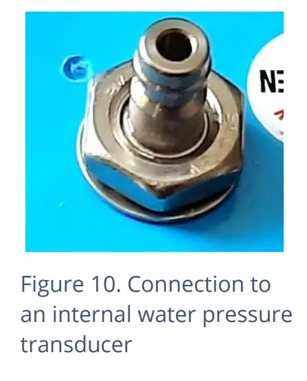
An alternative for water pressure measurement is for the transducer (sensor) to be built into the unit, as shown in Figure 10. This logger interface is known as an “Internal Pressure” type. It allows pressurized water to be connected to the logger directly, via the use of hoses fitted with a quick-release connector.
એન્ટેના માટે, એક અલગ પ્રકારના કનેક્ટરનો ઉપયોગ થાય છે. વિભાગ 5.18 નો સંદર્ભ લો.
The Multilog2 supports a variety of sensors and parameter measurements. Examples નીચે આપેલ છે: (મોડલ નંબર ઓર્ડર પર આધાર રાખે છે).
- દબાણ. Examples: – Direct connection to an internal transducer (referred to as an ‘internal’ pressure sensor). -Electrical connector for a wired transducer(referred to as an ‘external’ pressure sensor).
- અંતર to a water surface Example: – By using a SonicSens2 sensor. -By using a SonicSens3 sensor.
- પાણી depth.Examples: – By using a SonicSens2 or SonicSens3 sensor. -By use of a submerged pressure gauge.
- પાણી leak detection (from pressurized water pipes).Examples: – By use of a HWM Leak-Noise Sensor or Hydrophone.•Water (or Gas) Consumption (Flow rate / total consumption).Exampલેસ: - વિવિધ મીટર પલ્સ આઉટપુટ ફોર્મેટને અનુરૂપ વિવિધ 'ફ્લો' ચેનલો ઉપલબ્ધ છે.
- Temperature.Exampલે: – By use of a PT100 temperature sensor.
- સ્થિતિ InputExample: - ખુલ્લી/બંધ સ્વીચ શોધવા માટે.
- સ્થિતિ Output. Examples: – Pulse replication of Status Inputs. -To activate some external equipment.
- જીપીએસ input (communication from Global Positioning System satellites). Examples: – To determine current time (high accuracy).-To determine current location / confirm still at installation site.
- 0-1V input.(or 01-10V)(This is a generic sensor interface.The logger supports inputs from externally powered sensors).
- 4-20mA input. (This is a generic sensor interface.
- મોડબસ
- SDI-12The logger supports inputs from externally powered sensors Optionally, the logger can provide power to compatible sensors). (This is a widely used interface for sensor communications. The logger supports inputs from externally powered sensors. Optionally, the logger can provide power to compatible sensors). (This is a widely used interface for sensor communications. The logger supports inputs from externally powered sensors).
- (અન્ય). વધુ માહિતી માટે અથવા તમારી જરૂરિયાતોની ચર્ચા કરવા માટે તમારા વેચાણ પ્રતિનિધિનો સંપર્ક કરો.
For any given parameter, several sensors may be available with different types of electrical interface. Sensors provided by HWM will include a cable with a suitable connector for the supplied Multilog2.
ઇન્સ્ટોલેશન
ઇન્સ્ટોલેશન સ્ટેપ્સનો સારાંશ
- તપાસો કે કાર્યનું મૂલ્યાંકન કરવામાં આવ્યું છે અને કોઈપણ સલામતીનાં પગલાં અમલમાં છે. (દા.ત., સલામતીની સાવચેતીઓ, રક્ષણાત્મક કપડાં અને/અથવા ઉપયોગમાં લેવાતા સાધનો).
- Check the logger is suitable for use at the installation site.
- Check that you have the required sensors and antenna.
- ઉપલબ્ધ જગ્યામાં સાધનો ક્યાં સ્થિત હશે અને તમામ કેબલ અને કોઈપણ નળી યોગ્ય લંબાઈના છે તે ધ્યાનમાં લો.
- કોઈપણ દબાણ માપન બિંદુ સાથે જોડાવા માટે ચેક ફીટીંગ ઉપલબ્ધ છે.
- લોગર, કેબલ્સ અને સેન્સરને ઇલેક્ટ્રિકલ હસ્તક્ષેપના સ્ત્રોતો જેમ કે મોટર અથવા પંપથી દૂર રાખવા જોઈએ.
- કેબલ્સ અને હોઝને રૂટ અને સુરક્ષિત કરવા જોઈએ જેથી કરીને કોઈ જોખમ ન આવે. કોઈપણ સાધનને કેબલ, કનેક્ટર્સ અથવા હોઝ પર આરામ કરવાની મંજૂરી આપશો નહીં કારણ કે ક્રશ નુકસાન થઈ શકે છે.
- લોગર માટે યોગ્ય પ્રોગ્રામિંગ કેબલ પસંદ કરો અને તેને લોગર COMMS કનેક્ટર સાથે જોડો. IDT હોસ્ટ ડિવાઇસનો કનેક્શન પાથ પૂર્ણ કરો (વિભાગો 2.7 અને 2.8 જુઓ). લોગર સેટિંગ્સ વાંચવા માટે IDT નો ઉપયોગ કરો. (જ્યારે પણ જરૂર પડે ત્યારે માર્ગદર્શન માટે IDT વપરાશકર્તા-માર્ગદર્શિકાનો સંદર્ભ લો).
- લોગર ફર્મવેર અપડેટ કરો (જો જરૂરી હોય તો).
(Refer to the IDT manual for guidance; consider downloading any existing data from the logger prior to upgrade). - વર્તમાન લોગર સેટિંગ્સ તપાસવા અથવા સુધારવા માટે IDT નો ઉપયોગ કરો.
- લોગરમાં સ્થાનિક સમય-ઝોન પ્રોગ્રામ કરો (તપાસો અથવા સુધારો).
- માપન કરવા માટે સમય અંતરાલ સેટ કરો (ઓampલે અંતરાલ અને લોગ અંતરાલ). તેઓ તમારી એપ્લિકેશનની વિશિષ્ટ લોગીંગ આવશ્યકતાઓને અનુરૂપ હોવા જોઈએ (ઓછી કરોampબૅટરીના જીવનને જાળવવા માટે લિંગ દર).
- માપન માપવા માટે ચેનલ સેટિંગ્સ તપાસો / સંશોધિત કરોampદરેક ઇન્ટરફેસમાંથી લેસ અને જરૂરી ડેટાપોઇન્ટ્સ.
- Configure the logger channel to match the sensor or other equipment that the logger connects to.
(Check units of measure are correct, etc) - ખાતરી કરો કે સેન્સર યોગ્ય આઉટપુટ ચેનલ નંબર સાથે મેપ થયેલ છે; આ એક ઓળખકર્તા છે જેનો ઉપયોગ સર્વર પર લોગ થયેલ માપન ડેટા અપલોડ કરતી વખતે થાય છે. (એટલે કે, ચેનલ નંબર લોગર અને ડા વચ્ચે મેળ ખાતા હોવા જોઈએtaGખાધું).
(Note: For loggers using WITS protocol, requirements are different; refer to the guidance in the WITS supplement, MAN-147-0017). - પૃષ્ઠભૂમિ માપ s પર કોઈપણ જરૂરી આંકડાકીય કાર્યો લાગુ કરોampલૉગ કરેલા ડેટા-પોઇન્ટ્સ (સાચવેલા મૂલ્યો) પેદા કરવા માટે.
- Where required, undertake the setup of any additional options related to the channel. (E.g., add an initial meter reading, pulse replication setting, sensor calibration; these will be dependent on sensor and logger use).
- પ્રેશર સેન્સર માટે, તેમને ઇલેક્ટ્રિકલી જોડો પરંતુ સેન્સરને સ્થાનિક વાતાવરણીય દબાણમાં ખુલ્લા કરો અને માપન બિંદુ સાથે જોડાણ શરૂ કરતા પહેલા તેમને ફરીથી શૂન્ય કરો (IDT નો ઉપયોગ કરીને).
- સેન્સરને તેમના માપન બિંદુ પર ઇન્સ્ટોલ કરો (સ્થિતિ અને કનેક્ટ કરો).
- પાણી સાથેના કોઈપણ જોડાણોને બ્લીડ કરો.
- જ્યાં જરૂરી હોય ત્યાં, પ્રેશર ટ્રાન્સડ્યુસર સાથે જોડાયેલ કોઈપણ પાણી ભરેલી ટ્યુબિંગને હિમથી બચાવવા માટે ઇન્સ્યુલેટ કરો. (ઇન્સ્યુલેટીંગ પાઇપ કવર વિનંતી પર વધારાના ખર્ચે પૂરા પાડી શકાય છે અથવા હાર્ડવેર સ્ટોરમાંથી સ્થાનિક રીતે મેળવી શકાય છે).
- ખાતરી કરો કે સાઇટ પર બનાવેલા કોઈપણ વિદ્યુત જોડાણો શુષ્ક, ટકાઉ અને પાણી-ચુસ્ત હોય.
- આ માટે IDT નો ઉપયોગ કરો:
- લોગર તપાસો કે સેન્સર યોગ્ય રીતે કાર્ય કરી રહ્યા છે કે નહીં. (કેટલાક ઇન્સ્ટોલેશન પહેલા કરી શકાય છે; અન્ય ઇન્સ્ટોલેશન પછી).
- કોઈપણ એલાર્મ માટે લોગર સેટઅપ કરો. એલાર્મ સંદેશાઓને સક્રિય કરવા માટેની શરતો અને એલાર્મને સાફ કરવાની શરતો પણ ધ્યાનમાં લો.
- જરૂર મુજબ, ઉપકરણની સંચાર સેટિંગ્સ તપાસો / સંશોધિત કરો:
- સિમ સેટિંગ્સ (સેલ્યુલર નેટવર્કને ઍક્સેસ આપવા માટેના પરિમાણો).
- મોડેમ સેટિંગ્સ (સેલ્યુલર નેટવર્ક ટેકનોલોજી).
- ડેટા ડિલિવરી સેટિંગ્સ (સર્વર સંપર્ક વિગતો).
- કૉલ-ઇન સમય અને પ્રોટોકોલ સેટિંગ્સ.
- સાઇટ છોડતા પહેલા સેટિંગ્સમાં થયેલા કોઈપણ ફેરફારો સાચવવામાં આવ્યા છે કે નહીં તે ચકાસો. તપાસો કે લોગર "રેકોર્ડિંગ" સ્થિતિમાં છે.
- જ્યાં લોગર પાસે GPS એન્ટેના કનેક્શન હોય, ત્યાં સેટેલાઇટ કમ્યુનિકેશન્સ લેવા માટે GPS એન્ટેના ઇન્સ્ટોલ કરો (સ્થિતિ અને કનેક્ટ કરો).
- Use IDT to test the GPS installation is correctly working (GPS test).
- If used for obtaining a location fix, setup GPS location fix schedule and any GeoFence alarm requirements.
- Install (position and connect) the antenna for server communications.
- Use IDT to test the cellular communications performance.
- Ensure details of the site of logger deployment are recorded.
- (સર્વર માટે વહીવટ ઓફિસ સ્ટાફ દ્વારા નિયંત્રિત કરી શકાય છે, અથવા ઇન્સ્ટોલર HWM ડિપ્લોયમેન્ટ એપ્લિકેશનનો ઉપયોગ કરી શકે છે).
INSTALLING THE LOGGER
The logger must be mounted in a suitable location where the sensors to be attached can reach their intended installation points. Position loggers, sensors, and antenna away from sources of electrical interference such and motors or pumps. Cables and hoses should be routed without causing any hazards. Do not allow any equipment to rest on hoses, cables or connectors as crush damage can result.
The logger should be installed in the orientation shown in Figure 1 for optimum battery performance.
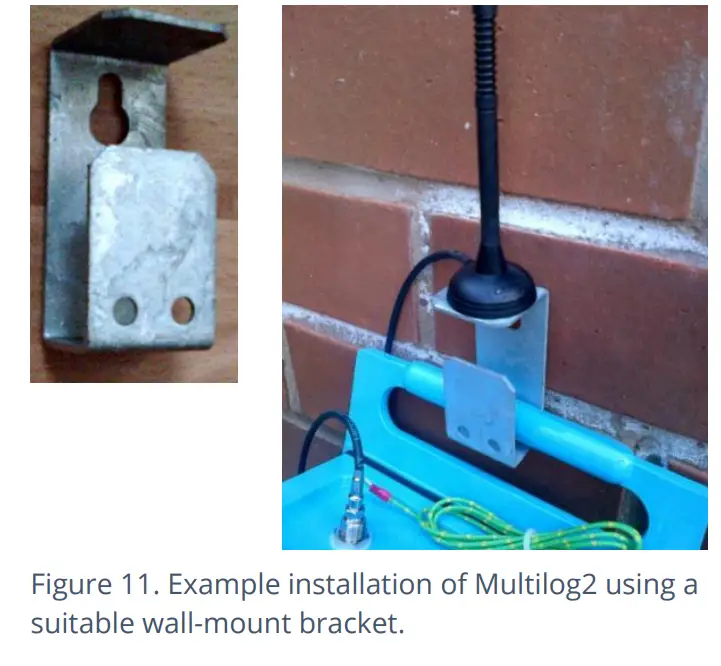
વોલ-માઉન્ટિંગ
The Multilog2 can be secured to a wall using a suitable bracket, an example of which is shown in Figure 11. Ensure the wall and fixings used are able to bear the weight of the logger and cables attached.
The bracket used may offer a potential mounting location for the antenna, although the installer should seek to find the optimal location for the antenna within the installation.
ELECTRICAL CONNECTIONS TO THE LOGGER
When making electrical connections to the logger (e.g., attaching a connector for a sensor), ensure the connector is correctly fitted. Both parts of the connector should be dry and free of debris. The connectors are keyed to ensure correct alignment of pins and receptacles. Align the sensor to the logger connector and push fully home. Then rotate the outer part of the sensor connector until it engages with the fastening mechanism and locks into place. The connector will then be secure and watertight.
કનેક્શન દૂર કરતી વખતે, ઉપર વર્ણવેલ પ્રક્રિયાના વિપરીત પગલાં અનુસરો. હંમેશા કનેક્ટર દ્વારા કનેક્શનને હેન્ડલ કરો; કેબલ ખેંચશો નહીં કારણ કે આનાથી નુકસાન થઈ શકે છે.
બધા કેબલને રૂટ કરો જેથી કોઈ સંભવિત જોખમ ન બને અને યોગ્ય ટાઈનો ઉપયોગ કરીને તેને સુરક્ષિત રીતે સ્થાને ગોઠવો.
For antenna, follow the steps given in section 5.18.
ફેક્ટરી સેટિંગ્સ
નોંધ: લોગર પાસે સામાન્ય રીતે શિપિંગ પહેલા ફેક્ટરી દ્વારા પૂર્વ-પ્રોગ્રામ કરેલ સેટિંગ્સ હશે. જો કે, સ્થાપિત સાઇટ પર ઉપયોગ માટે સેટિંગ્સ યોગ્ય છે તેની પુષ્ટિ કરવાની જવાબદારી સ્થાપકની છે.
જો તમારી પાસે ચોક્કસ જરૂરિયાતો હોય તો લોગર્સને ઓર્ડર કરતી વખતે તમારા HWM વેચાણ પ્રતિનિધિ સાથે આ અંગે ચર્ચા કરી શકાય છે.
જ્યાં જરૂર હોય ત્યાં, IDT નો ઉપયોગ લોગર સેટિંગ્સ તપાસવા અથવા તેમાં કોઈપણ ફેરફાર કરવા માટે થઈ શકે છે.
મોટાભાગના સેન્સર ઇન્ટરફેસ માટે, IDT વપરાશકર્તા-માર્ગદર્શિકામાં સામાન્ય માર્ગદર્શનને અનુસરો; લોગર વર્ણન અને ભૂતપૂર્વનું પાલન કરે છેamples of setup provided therein. However, some HWM sensors require specialized setup screens or have their own user-guide which provides further guidance.
પ્રેશર સેન્સર ઇનપુટ્સ
રી-ઝીરો સુવિધા (સ્થાનિક વાતાવરણને સંબંધિત દબાણ માટે)
Pressure sensors supplied by HWM normally measure pressure relative to atmospheric pressure. Since there can be some variation in local atmospheric pressure (e.g., due to altitude), the loggers have a facility to re-zero the pressure sensor.
આ વાતાવરણીય હવાના સંપર્કમાં રહેલા સેન્સર સાથે કરવું આવશ્યક છે.
Prior to connecting the transducer to the actual measuring point, leave it exposed to air. Then “re-zero” the sensor using the method found in the IDT user-guide.
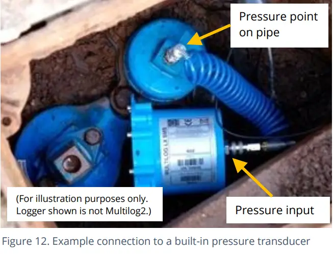
પ્રેશર સેન્સર (આંતરિક)
પ્રેશર ઇનપુટ બિલ્ટ-ઇન ટ્રાન્સડ્યુસર તરીકે રજૂ કરી શકાય છે (આકૃતિ 10 માં, પૃષ્ઠ 14 પર બતાવ્યા પ્રમાણે), જે ક્વિક-રિલીઝ કનેક્ટરનો ઉપયોગ કરીને નળી દ્વારા પ્રવાહી સાથે સીધો જોડાય છે.
નોંધ: જો જરૂરી હોય તો, ફરીથી શૂન્ય (સ્થાનિક વાતાવરણીય દબાણ) પ્રક્રિયામાંથી પસાર થયા વિના સેન્સરને માપન બિંદુ સાથે કનેક્ટ કરશો નહીં.
યોગ્ય ઇન્ટરકનેક્ટિંગ નળીનો ઉપયોગ કરીને લોગરના પ્રેશર ટ્રાન્સડ્યુસર સાથે પાઇપ (માપન બિંદુ) પરના પ્રેશર ટેપિંગને કનેક્ટ કરો. (ભૂતપૂર્વ માટેample, આકૃતિ 12 જુઓ.) યોગ્ય કામગીરી માટે, નળીમાંથી લોહી નીકળ્યું છે તેની ખાતરી કરો.
આ ઈન્ટરફેસ ફેક્ટરી માપાંકિત છે. કોઈ ઑન-સાઇટ કેલિબ્રેશન જરૂરી નથી.
નોંધ: Add insulation to the pipe and logger to prevent freezing.
If the water in the hose or the logger itself freezes, there is a danger of permanent damage to the pressure transducer.
પ્રેશર સેન્સર (બાહ્ય)
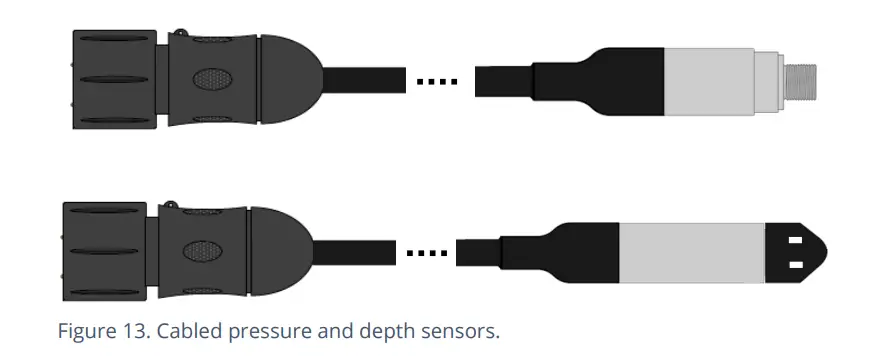
A pressure input may be presented as an electrical interface, using a 4-pin or 6-pin MIL-Spec connector (see Figure 9 on page 14).
Cabled pressure sensors for the Multilog2 are available from HWM. For most situations, sealed type pressure (or depth) sensors are used, and the sensor will be wired directly to the connector, as shown in Figure 13.
લોગર માપન કરતા પહેલા (અને દરમિયાન) સેન્સરને અસ્થાયી રૂપે પાવર લાગુ કરે છે.
લોગર ઇન્ટરફેસને "પ્રેશર (20 બાર)" (અથવા તેના જેવું) લેબલ કરવામાં આવશે.
કનેક્ટર્સના પિનઆઉટ નીચે બતાવેલ છે.
| લોગર બલ્કહેડ કનેક્ટર પિનઆઉટ: 4-પિન બાહ્ય દબાણ | |||
| A | B | C | D |
| વી (+); (PWR) | વી (+); (સિગ્નલ) | વી (-); (PWR) | વી (-); (સિગ્નલ) |
| લોગર બલ્કહેડ કનેક્ટર પિનઆઉટ: 6-પિન બાહ્ય દબાણ | |||||
| A | B | C | D | E | F |
| વી (+); (PWR) | વી (+); (સિગ્નલ) | વી (-); (PWR) | વી (-); (સિગ્નલ) | GND / સ્ક્રીન | (જોડાયેલ નથી) |
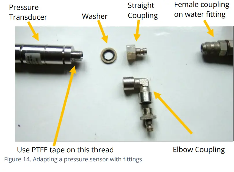
Where a pressure transducer has a threaded end for connection to the pressure measurement point, fittings may be required to modify the connection (e.g., a quick-release connector for connection to a hose). For example, આકૃતિ 14 જુઓ.
Assemble any fittings prior to connecting to the logger.
Straight or elbow styles of coupling kits are available.
ખાતરી કરો કે લોગર પાસે દબાણ અથવા ઊંડાઈ સેન્સર માટે યોગ્ય ઇન્ટરફેસ છે. પછી સેન્સરને સંબંધિત લોગર ઇન્ટરફેસ સાથે કનેક્ટ કરો.
નોંધ: માપાંકન પ્રક્રિયામાંથી પસાર થતાં પહેલાં સેન્સરને માપન બિંદુ સાથે કનેક્ટ કરશો નહીં (નીચે જુઓ) અને પછી ફરીથી શૂન્ય (સ્થાનિક વાતાવરણીય દબાણ સાથે).
પ્રેશર સેન્સર માટે, માપન બિંદુ સાથે જોડો અને (જો લાગુ હોય તો) કોઈપણ કનેક્ટિંગ નળીને બ્લીડ કરો.
ડેપ્થ સેન્સર માટે, જો જરૂરી હોય તો ફિક્સ્ચર (દા.ત., વાહક પ્લેટ અથવા એન્કરિંગ કૌંસ) નો ઉપયોગ કરીને, સેન્સરને પાણીની ચેનલના તળિયે ભારિત અથવા સુરક્ષિત રીતે માઉન્ટ કરવું જોઈએ. સેન્સરને સ્થાનમાંથી બહાર કાઢવા અથવા કોઈપણ કનેક્શન્સને તણાવ આપવા માટે કેબલ પર ચાલતા પાણીને કાર્ય કરતા અટકાવવા માટે કેબલ પણ સ્થાને સુરક્ષિત હોવી જોઈએ.
માપાંકન પ્રક્રિયા (કેબલમાંથી માપાંકન મૂલ્યોનો ઉપયોગ કરીને):
સેન્સરનો ઉપયોગ કરતા પહેલા, સાચા રીડિંગ્સ આપવા માટે લોગર અને સેન્સરની જોડીને માપાંકિત કરવી આવશ્યક છે.
આ પદ્ધતિનો ઉપયોગ ઇન્સ્ટોલર દ્વારા લોગર સાથે પ્રેશર સેન્સરને જોડી અને માપાંકિત કરવા માટે કરી શકાય છે.
HWM સપ્લાય કરેલ પ્રેશર/ડેપ્થ સેન્સર સામાન્ય રીતે કેબલ પર દર્શાવેલ માપાંકન મૂલ્યો ધરાવે છે (આકૃતિ 15 જુઓ). IDT વપરાશકર્તા-માર્ગદર્શિકામાં માર્ગદર્શનનો ઉપયોગ કરીને લોગરમાં કેબલ પરના કેલિબ્રેશન લેબલમાંથી વિગતો ઉમેરવા માટે IDT નો ઉપયોગ કરો.
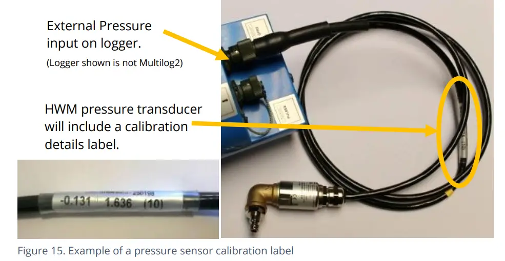
કેલિબ્રેશન પ્રક્રિયા દબાણ સેન્સરના પુનઃ શૂન્ય પહેલા થવી જોઈએ.
કેલિબ્રેશન પ્રક્રિયા અને ફરીથી શૂન્ય પ્રક્રિયાને અનુસર્યા પછી, ટ્રાન્સડ્યુસર તેના માપન બિંદુ પર સ્થિત (અથવા ફીટ) કરી શકાય છે.
સેન્સરથી માપ લેવા માટે લોગર યોગ્ય રીતે સેટ કરેલું હોવું જોઈએ. વધુ વિગતો માટે IDT વપરાશકર્તા-માર્ગદર્શિકાનો સંદર્ભ લો.
માપાંકન પ્રક્રિયા (લાગુ દબાણનો ઉપયોગ કરીને):
આ પદ્ધતિનો ઉપયોગ અધિકૃત સેવા કેન્દ્ર દ્વારા લોગર સાથે પ્રેશર સેન્સરને જોડી અને માપાંકિત કરવા માટે કરી શકાય છે.
પદ્ધતિમાં ટ્રાન્સડ્યુસર પર સંદર્ભ દબાણ લાગુ કરવું અને માપાંકન મૂલ્યોનું કોષ્ટક બનાવવાનો સમાવેશ થાય છે.
ફ્લો સેન્સર ઇનપુટ (મીટર પલ્સ કલેક્શન)
પૂરા પાડવામાં આવેલ મોડેલના આધારે, લોગરમાં 0 થી 6 ફ્લો ઇનપુટ્સ હોઈ શકે છે. આ ડિજિટલ ઇનપુટ્સ છે, જે સ્વીચ (ઇન્સ્ટોલ કરેલ મીટર દ્વારા સક્રિય) ની ખુલ્લી અથવા બંધ સ્થિતિને સમજવા માટે રચાયેલ છે. ફ્લો ચેનલ(ઓ) નો ઉપયોગ કરવા માટે, લોગરને દરેક મીટર પલ્સ શું રજૂ કરે છે તે જાણવા માટે (IDT નો ઉપયોગ કરીને) સેટઅપ કરવું આવશ્યક છે.
ફ્લો ચેનલ્સ અને ઇનપુટ સિગ્નલનું સમજૂતી
Flow of a fluid in a pipe is usually detected by a meter, which produces pulses related to the volume of fluid passing through it. There are several types of meters; some can detect both forward flow and reverse flow (bi-directional flow); some can detect flow in one direction only (uni-directional flow). There are therefore several ways of implementing the meter pulse output signals from a meter. Your logger must have the correct interface and settings for the signaling from the meter to be compatible with it.
The Multilog2 Flow inputs sometimes require two input signals in order to work with the meter-pulse signaling of certain meters. A pair of inputs can therefore sometimes be configured to operate as a single channel. Other meter types only require one signal, so the pair of inputs can operate as two separate channels.
The pair of Flow signals can be labeled in one of the following ways:
| વૈકલ્પિક સિગ્નલ નામો | ||||
| Pair of FLOW
સંકેતો |
ફ્લો ઇનપુટ ૧ | ફ્લો 1 | કઠોળ | પ્રવાહ (આગળ) |
| ફ્લો ઇનપુટ ૧ | ફ્લો 2 | દિશા | પ્રવાહ (વિપરીત) | |
| સામાન્ય | જીએનડી | |||
The labeling depends on the factory default for the configuration of the Flow channels on your logger model-number, but sometimes alternative types of configuration can be achieved by changing logger settings.
જ્યાં લોગરને ફેક્ટરી દ્વારા માત્ર 1 ફ્લો ચેનલ (ડેટાપોઇન્ટ સ્ટ્રીમ) બનાવવા માટે પૂર્વ-રૂપરેખાંકિત કરવામાં આવે છે, ત્યાં ઇનપુટ્સની જોડીનો ઉપયોગ ત્રણમાંથી એક રીતે કરી શકાય છે:
(1) Input 1 can be used with a Uni-directional meter (one which only measures forward flow / consumption).
આ રૂપરેખાંકનમાં ઉપયોગ માટે:
• Input 1 acts to collect meter pulses, and
ઇનપુટ 2 સામાન્ય રીતે ડિસ્કનેક્ટેડ છોડી દેવામાં આવે છે (અથવા 'T' તરીકે ઉપયોગ કરવા માટે ફાળવવામાં આવે છે).amp(એલાર્મ' તરીકે ઓળખાય છે, અથવા સ્ટેટસ ઇનપુટ તરીકે વપરાય છે).
(૩) ઇનપુટ ૧ અને ૨ નો ઉપયોગ દ્વિ-દિશાત્મક મીટર (જે આગળ અને વિપરીત પ્રવાહ બંનેને માપી શકે છે) સાથે જોડી તરીકે કરી શકાય છે.
આ રૂપરેખાંકનમાં ઉપયોગ માટે:
• Input 1 acts to collect meter pulses, and
• input 2 is used for the flow direction indication from the meter
(open = forward flow, closed = reverse flow).
(૩) ઇનપુટ ૧ અને ૨ નો ઉપયોગ દ્વિ-દિશાત્મક મીટર (જે આગળ અને વિપરીત પ્રવાહ બંનેને માપી શકે છે) સાથે જોડી તરીકે કરી શકાય છે.
આ રૂપરેખાંકનમાં ઉપયોગ માટે:
• Input 1 acts to collect meter pulses (forward flow direction), and
• input 2 acts to collect meter pulses (reverse flow direction).
Where the logger is pre-configured by the factory to produce 2 Flow channels
(ડેટાપોઇન્ટ સ્ટ્રીમ્સ), ઇનપુટ્સની જોડીનો ઉપયોગ 2 સ્વતંત્ર યુનિ-ડાયરેક્શનલ ફ્લો ઇનપુટ ચેનલો (ચેનલો 1 અને 2) તરીકે થઈ શકે છે.
દરેક ઇનપુટનો ઉપયોગ યુનિ-ડાયરેક્શનલ મીટર (જે ફક્ત આગળના પ્રવાહ / વપરાશને માપે છે) સાથે કરી શકાય છે.
લોગર 4-પિન બલ્કહેડ કનેક્ટર દ્વારા
Multilog2 Flow signal inputs are presented on a 4-pin connector (see Figure 9 on page 14). Each connector has a pair of Flow signal inputs.
આ કનેક્ટરનો પિનઆઉટ નીચે દર્શાવેલ છે:
| લોગર બલ્કહેડ કનેક્ટર પિનઆઉટ: 4-પિન ફ્લો ઇનપુટ્સ | ||||
| પિન | A | B | C | D |
| સિગ્નલ | (જોડાયેલ નથી) | ફ્લો ઇનપુટ ૧ | ફ્લો_જીએનડી | ફ્લો ઇનપુટ ૧ |
Check the meter to which the logger is going to be connected and ensure its meter pulse signaling method is understood, along with the significance of each meter pulse.
Connect the logger to the meter-pulse outputs of the meter using a suitable cable. If cables with bare tails have to be interconnected, refer to the guidance in section 5.5.
Use IDT to complete the setup, ensuring the logger is correctly set to interpret the meter pulses. If the logger is required to keep track of the meter counter display, take an initial reading of the meter counter and program it into the logger. The logger uploads additional consumption regularly, so a meter reading can be made remotely.
સાધનસામગ્રી સાથે અનટર્મિનેટેડ કેબલ વાયરને કનેક્ટ કરવું
ટર્મિનેટેડ ન હોય તેવા કેબલનો ઉપયોગ કરતી વખતે, ઇન્સ્ટોલરે સાઇટ પરના અન્ય સાધનો સાથે પોતાનું કનેક્શન બનાવવું પડશે.
When making a connection to Multilog2 you will normally need to splice the bare tails together. It is important that a waterproof connector housing is used, such as the “Tuff-Splice” enclosure available from HWM.
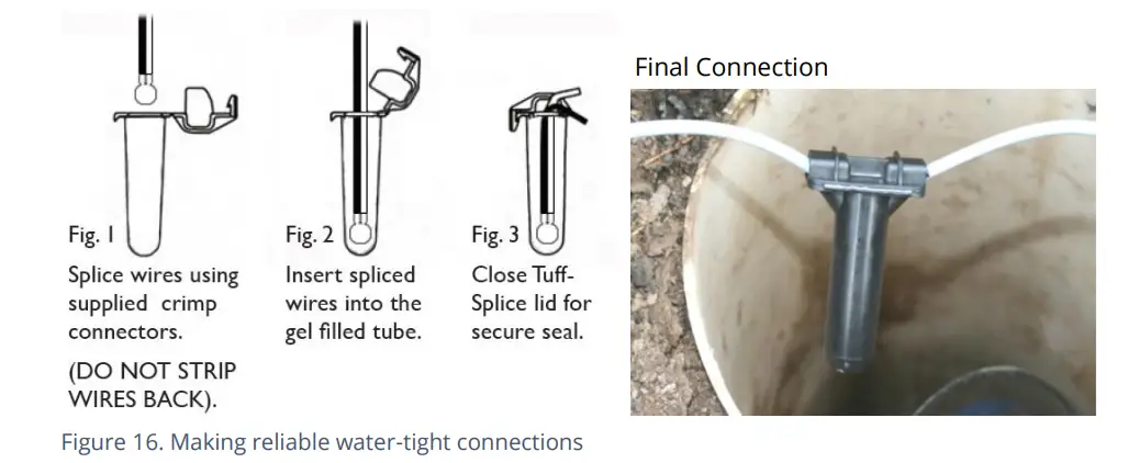
નોંધ: Long data connections should always be made using screened cable. The use of screened cable will ensure maximum rejection of interference from outside sources. Always use a common ground point without creating ground loops.
સ્ટેટસ ઇનપુટ
The Status Input pins are a re-purposed use of the Flow input electronics (see section 5.4). A change in the software driver for the connector gives the input pins a different functionality.
ઇન્ટરફેસને 'સ્ટેટસ' અથવા 'ડ્યુઅલ સ્ટેટસ' તરીકે લેબલ કરવામાં આવશે.
આ કનેક્ટરનો પિનઆઉટ નીચે દર્શાવેલ છે:
| Logger bulkhead connector pinout : 4-pin Status Inputs | ||||
| પિન | A | B | C | D |
| સિગ્નલ | (જોડાયેલ નથી) | Status Input 1 | Status_GND | Status Input 2 |
સ્વીચ સંપર્કો શોધવા માટે સામાન્ય હેતુ માટે સ્ટેટસ ઇનપુટ સિગ્નલો ગોઠવી શકાય છે. આના ઘણા ઉપયોગો છે.
દા.ત
- સુરક્ષા હેતુઓ માટે દરવાજા / બારી / સાધનો-પ્રવેશના મુખની શોધ.
- ફ્લો ચેનલ પર 'સ્પેર' પિનનો ઉપયોગ 'ટી' જનરેટ કરવા માટે કરી શકાય છેamper’ alarm in the event that the logger cable is cut or removed from the meter.
(The meter must support this facility by providing a closed loop from the tampરીટર્ન પિન, Status_GND) માં er ઇનપુટ.
યોગ્ય કેબલનો ઉપયોગ કરીને લોગરને બાહ્ય ઉપકરણ સાથે જોડો. જો ખાલી પૂંછડીવાળા કેબલને એકબીજા સાથે જોડવા પડે, તો વિભાગ 5.5 માં આપેલ માર્ગદર્શિકાનો સંદર્ભ લો.
સેટઅપ પૂર્ણ કરવા માટે IDT નો ઉપયોગ કરો, ખાતરી કરો કે લોગર ઇચ્છિત એલાર્મ જનરેટ કરવા માટે સેટ થયેલ છે.
OUTPUTS (DIGITAL SWITCH: OPEN/CLOSED)
Multilog2 Outputs are presented on a 3-pin connector (similar to Figure 8 on page 14). Up to four outputs can be supported. Each connector has a pair of outputs.
The interface will be labeled as ‘Dual Output’.
આ કનેક્ટરનો પિનઆઉટ નીચે દર્શાવેલ છે:
| લોગર બલ્કહેડ કનેક્ટર પિનઆઉટ: 3-પિન આઉટપુટ | |||
| પિન | A | B | C |
| સિગ્નલ | આઉટપુટ 1 | આઉટપુટ 2 | જીએનડી |
લોગર આઉટપુટને કોઈ પાવર સપ્લાય કરતું નથી. આઉટપુટ ઇલેક્ટ્રોનિક સ્વીચ (ટ્રાન્ઝિસ્ટર) નું સ્વરૂપ લે છે, જે કાં તો ખુલ્લું અથવા બંધ હોઈ શકે છે. જ્યારે બંધ થાય છે, ત્યારે વર્તમાન પાથ અથવા આઉટપુટ પિન અને ગ્રાઉન્ડ વચ્ચે હોય છે.
મહત્તમ રેટ કરેલ વોલ્યુમtage 12V (DC) છે
મહત્તમ રેટેડ વર્તમાન 120mA છે.
આઉટપુટ પિનનો સામાન્ય ઉપયોગ પલ્સ રેપ્લિકેશન (મીટર પલ્સ જે ફ્લો ચેનલોમાં ઇનપુટ હોય છે) માટે થાય છે. જ્યાં આ અમલમાં મૂકવામાં આવે છે:
- ફ્લો ઇનપુટ 1 ને આઉટપુટ 1 માં પ્રતિકૃતિ કરવામાં આવે છે.
- ફ્લો ઇનપુટ 2 ને આઉટપુટ 2 માં પ્રતિકૃતિ કરવામાં આવે છે.
- ફ્લો ઇનપુટ 3 ને આઉટપુટ 3 માં પ્રતિકૃતિ કરવામાં આવે છે.
- ફ્લો ઇનપુટ 4 ને આઉટપુટ 4 માં પ્રતિકૃતિ કરવામાં આવે છે.
આઉટપુટ સિગ્નલોનો ઉપયોગ બાહ્ય ઉપકરણોને સક્રિય કરવા માટે પણ થઈ શકે છે.
આઉટપુટનો ઉપયોગ કરવા માટે, યોગ્ય કેબલ જરૂરી છે (ચોક્કસ જરૂરિયાતો લોગર કયા સાધનોનો ઉપયોગ કરી રહ્યો છે તેના પર નિર્ભર રહેશે; તમારા HWM પ્રતિનિધિ સાથે ચર્ચા કરો). જો ખાલી પૂંછડીવાળા કેબલને એકબીજા સાથે જોડવાની જરૂર હોય, તો વિભાગ 5.5 માં માર્ગદર્શનનો સંદર્ભ લો.
આઉટપુટ માટેની તમારી એપ્લિકેશનના આધારે સેટઅપ પૂર્ણ કરવા માટે IDT નો ઉપયોગ કરો.
બાહ્ય બેટરી
ઘણા ઇન્સ્ટોલેશન માટે બાહ્ય બેટરીનો ઉપયોગ વૈકલ્પિક છે પરંતુ જરૂરી સેવા લંબાઈ મેળવવા માટે લોગરને ટેકો આપવાની જરૂર પડી શકે છે.
શ્રેષ્ઠ બેટરી લાઇફ માટે, બાહ્ય બેટરીને તેના પસંદગીના ઓરિએન્ટેશનમાં દિશામાન કરો (બેટરી પરના લેબલિંગનો સંદર્ભ લો). બેટરી ભારે ઉપકરણો છે. બેટરીને સ્થાન આપતી વખતે, તપાસો કે તે ઇન્સ્ટોલેશનની અંદર કોઈપણ કેબલ અથવા ટ્યુબને કચડી રહી નથી. ખાતરી કરો કે બેટરી તેની ઇન્સ્ટોલેશન સ્થિતિમાં સુરક્ષિત છે (જેથી તે પડી ન શકે). પછી તેને લોગર સાથે કનેક્ટ કરો.
બાહ્ય બેટરી માટે લોગર કનેક્શન (6-પિન અથવા 10 પિન) કનેક્ટર દ્વારા રજૂ કરવામાં આવશે જે પ્રોગ્રામિંગ ઇન્ટરફેસ ("COMMS" લેબલ થયેલ) સાથે શેર કરેલ છે.
બાહ્ય બેટરી પેકને લોગર સાથે જોડવા માટે ઉપયોગમાં લેવાતા કેબલમાં ફક્ત પાવર સપ્લાય માટે જરૂરી પિનનો સમાવેશ થશે; સંદેશાવ્યવહાર માટે સોંપેલ પિન ફીટ કરવામાં આવશે નહીં.
જ્યારે પણ લોગર પ્રોગ્રામિંગ કેબલ જોડવાની જરૂર હોય ત્યારે બાહ્ય બેટરી કનેક્શન અસ્થાયી રૂપે ડિસ્કનેક્ટ કરવું આવશ્યક છે.
SONICSENS 3 (ULTRASOUND DISTANCE / DEPTH SENSOR)
Where a SonicSens3 interface is available on your logger, it will have a 6-pin connector, similar to that shown in Figure 8, on page 14.
The interface provides power and communications to the sensor, which measures distance to a fluid surface. By input of other parameters (e.g., distance from the bottom of the water channel) the logger can calculate water depth. It can also derive a variety of other measurements such as flow rates if situated near an open weir.
ઓપરેશન માટે સેન્સરને કેવી રીતે ઇન્સ્ટોલ અને સેટઅપ કરવું તેની સૂચનાઓ માટે SonicSens-3 વપરાશકર્તા-માર્ગદર્શિકા (MAN-153-0001) નો સંદર્ભ લો.
નોંધ: Multilog2 loggers are not of an intrinsically safe construction, and so cannot be used within an environment where a potentially explosive atmosphere may be present.
SONICSENS 2 (ULTRASOUND DISTANCE / DEPTH SENSOR)
Where a SonicSens2 interface is available on your logger, it will have a 4-pin connector, as shown in Figure 8, on page 14.
The interface provides communications to the sensor, which measures distance to a fluid surface. By input of other parameters (e.g., distance from the bottom of the water channel) the logger can calculate water depth. It can also derive a variety of other measurements such as flow rates if situated near an open weir.
ઓપરેશન માટે સેન્સરને કેવી રીતે ઇન્સ્ટોલ અને સેટઅપ કરવું તેની સૂચનાઓ માટે SonicSens-2 વપરાશકર્તા-માર્ગદર્શિકા (MAN-115-0004) નો સંદર્ભ લો.
નોંધ: Multilog2 loggers are not of an intrinsically safe construction, and so cannot be used within an environment where a potentially explosive atmosphere may be present.
તાપમાન ઇનપુટ (RTD – PT100)
The logger may be constructed with a 4-pin connector (see Figure 9, on page14) for connection of a temperature sensor. Typically, this will be a PT100 RTD sensor. The logger interface will be labeled “TEMP” or similar).
કનેક્ટર્સનું પિનઆઉટ નીચે બતાવેલ છે.
| Logger bulkhead connector pinout : 4-pin Temperature (RTD -PT100) | |||
| A | B | C | D |
| તાપમાન_V + | તાપમાન + | તાપમાન_V – | તાપમાન - |
| Logger bulkhead connector pinout : 6-pin Temperature (RTD -PT100) | |||||
| A | B | C | D | E | F |
| તાપમાન_V + | તાપમાન + | તાપમાન_V – | તાપમાન - | GND / સ્ક્રીન | (જોડાયેલ નથી) |
તાપમાન સેન્સરનો ઉપયોગ કરવા માટે, ઇનપુટનું માપાંકન જરૂરી છે.
When ordered with a temperature sensor from HWM, the sensor will have the correct connector fitted for the Multilog2 logger. The logger input will also be factory calibrated for use with the supplied sensor.
LNS ઇનપુટ (લીક-નોઇઝ સેન્સર / હાઇડ્રોફોન)
The logger may be constructed with a 4-pin connector (see Figure 9, on page14) for connection of a high sensitivity audio sensor, used for detecting the noise of a leak from a pressurized water pipe.
The interface will be labeled ‘LNS INPUT’ (or similar).
Typically, the sensor will be a Leak Noise Sensor from one of the HWM PR4LNS-1 family. The Multilog2 is also compatible with the Hydrophone-2 sensor (and its earlier version, Hydrophone). Both use the same connector. There are only minor differences in setup of the logger for their use. There are significant differences in their installation methods.
ચુંબકીય પ્રકાર LNS સેન્સરનું સ્થાપન:
લોગર પાઇપ નેટવર્કમાંથી ઉત્પાદિત અવાજો સાંભળવા માટે સેન્સરનો ઉપયોગ કરે છે. તે પછી નજીકમાં લીક થવાની સંભાવના છે કે કેમ તે નક્કી કરવા માટે તે વિશેષ અલ્ગોરિધમનો ઉપયોગ કરે છે.
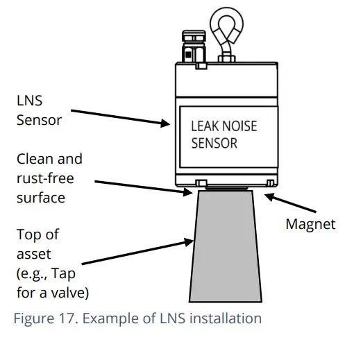
LNS એકમની અંદર ઓડિયો સેન્સર ઉપયોગ માટે પાઇપ નેટવર્કની બહાર જોડાયેલ છે, સામાન્ય રીતે તેને ચેમ્બરની અંદર મેટલ પાઇપ એસેટ (હાઈડ્રન્ટ અથવા વાલ્વ) સાથે જોડવા માટે ચુંબકનો ઉપયોગ કરે છે. આકૃતિ 17 નો સંદર્ભ લો.
સેન્સર આદર્શ રીતે સંપત્તિની ઉપરની સપાટી સાથે જોડાયેલ હોવું જોઈએ, જેમાં સેન્સર નીચેની તરફ હોય. (આ સેન્સર પડવાનું જોખમ ઘટાડે છે).
સેન્સર ઇન્સ્ટોલ કરતા પહેલા, અસ્કયામત જોડાણ બિંદુને સાફ કરો અને વાયર બ્રશનો ઉપયોગ કરીને તેમાંથી કોઈપણ કાટ દૂર કરો; આ ખાતરી કરે છે કે પાઇપ સાથે સારો સંપર્ક કરવામાં આવશે (ધ્વનિ ચલાવવા માટે).
પછી સેન્સર કેબલને લોગર સાથે કનેક્ટ કરો.
હાઇડ્રોફોન-2 સેન્સરનું સ્થાપન:
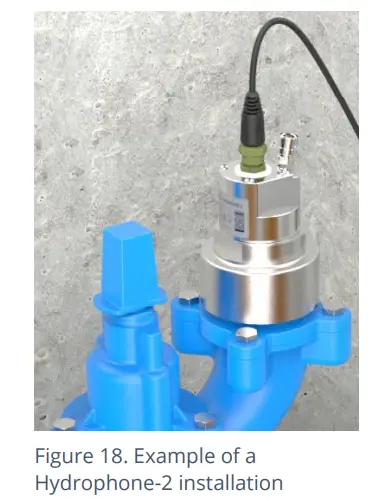
હાઇડ્રોફોન-2 યુનિટની અંદર ઓડિયો સેન્સર સીધા જ પાઇપની અંદરના પાણી સાથે એક્સેસ પોઈન્ટ દ્વારા જોડાય છે, જેમ કે હાઇડ્રેન્ટ (જુઓ આકૃતિ 18). આ તેને LNS કરતાં વધુ લાંબી કામગીરી આપે છે, ખાસ કરીને પ્લાસ્ટિક પાઈપોમાં.
Installing the unit into the water network can be a dangerous operation unless carried out correctly. Refer to the Hydrophone-2 user-guide
(MAN-165-0001) for installation and use details.
લોગર અને સર્વરનું વર્તન:
The use of a Leak-Noise sensor or Hydrophone can cause some changes (additions) to the logger’s pattern of behavior. This section provides a summary of the loggers use of the sensors; For a detailed explanation, refer to the PermaNet+ with Hydrophone-2 user-guide (MAN-148-0007).
લોગરના આઉટપુટમાં વિવિધ પરિમાણોનો સમાવેશ થશે, જેમાંથી દરેક ડેટાપોઇન્ટ ચેનલ હશે.
લીક ડિટેક્શન પેરામીટર્સમાં આનો સમાવેશ થશે:
- સ્તર
- ફેલાવો
- Leak / No-leak judgment
મોટાભાગના વોટર નેટવર્ક ઇન્સ્ટોલેશન માટે, લોગર સામાન્ય રીતે દિવસમાં એકવાર વ્યાપક લીક પરીક્ષણ ચક્ર ચલાવશે. જો કે, જ્યારે ટ્રંક મેઈન જેવા વોટર નેટવર્કના નિર્ણાયક ભાગોનું નિરીક્ષણ કરવા માટે ઉપયોગ કરવામાં આવે છે, ત્યારે વૈકલ્પિક પરીક્ષણ ચક્ર ઉપલબ્ધ છે (જેને 'ટ્રંક મેઈન' મોડ કહેવાય છે); સંભવિત લીક સમસ્યાઓના અગાઉના સંકેત પ્રદાન કરવા માટે, આ એક ટૂંકી અવાજ મૂલ્યાંકન પરીક્ષણ વધુ વારંવાર ચલાવે છે.
લીક ડિટેક્શન પેરામીટર્સ ઉપરાંત, લોગર અન્ય પ્રકારના પૂરક ડેટાનું ઉત્પાદન કરી શકે છે, જેમ કે સાઉન્ડ રેકોર્ડિંગ (ઓડિયો files). આને સર્વર પર પણ અપલોડ કરવામાં આવે છે અને અનુભવી વપરાશકર્તા દ્વારા તેને દૂરથી સાંભળી શકાય છે, તે નક્કી કરવા માટે કે અવાજ પાણીના લીક જેવો છે કે કેમ.
If the logger can find a highly accurate time reference from where it is installed
(e.g., from the cellular communications network or a GPS satellite), a high-accuracy time-stamp ઓડિયો સાથે લિંક કરવામાં આવશે file.
સર્વર ઘણા લોગર્સ (એકબીજા માટે સ્થાનિક) જૂથ બનાવવાની સુવિધા પૂરી પાડી શકે છે જે લીકની જાણ કરી રહ્યા છે અને પછી સાઉન્ડ રેકોર્ડિંગ માટે તપાસો. ઑડિયો રેકોર્ડિંગ બરાબર તે જ સમયે કરવામાં આવ્યા હતા તે પ્રદાન કરીને, સર્વર તેનો ઉપયોગ પાઇપ નેટવર્ક પર સંભવિત લીકની સ્થિતિને શોધવાનો પ્રયાસ કરવા માટે કરી શકે છે.
અન્ય ડેટા કે જે લોગરમાંથી મેળવી શકાય છે તે નોઈઝ હિસ્ટોગ્રામ છે (પાઈપના અવાજની લાક્ષણિકતાઓમાં તાજેતરમાં કોઈ ફેરફાર થયો છે કે કેમ તેનું મૂલ્યાંકન કરવા).
ANALOGUE VOLTAGE ઇનપુટ (0-1V, 0-10V)
લોગરને સેન્સરના જોડાણ માટે 4-પિન કનેક્ટર (આકૃતિ 8, પૃષ્ઠ 14 પર જુઓ) સાથે બાંધવામાં આવી શકે છે જે આઉટપુટ વોલ્યુમનો ઉપયોગ કરે છે.tage level as a method of signalling. Both a 0-1V and a 0-10V input interfaces are available on Multilog2 but must be specified at the time of ordering.
લોગર સેન્સરને શક્તિ પ્રદાન કરતું નથી; તેની પાસે શક્તિનો પોતાનો સ્ત્રોત હોવો જોઈએ.
આ કનેક્ટરનો પિનઆઉટ નીચે દર્શાવેલ છે:
| લોગર બલ્કહેડ કનેક્ટર પિનઆઉટ : વોલ્યુમtage ઇનપુટ 0-1V (& 0-10V) | ||||
| પિન | A | B | C | D |
| સિગ્નલ | (જોડાયેલ નથી) | 0-10V + /
0-1V + |
(જોડાયેલ નથી) | 0-10V – /
0-1V - |
આ ઈન્ટરફેસ સાથે વિવિધ પ્રકારના સેન્સર ઉપલબ્ધ છે.
When ordered from HWM, the sensor will have the correct connector fitted for the Multilog2 logger.
ઇન્સ્ટોલરે આઇડીટીનો ઉપયોગ લોગરની સેટિંગ્સની પુષ્ટિ કરવા અથવા તેને યોગ્ય રીતે માપવા માટે અને ભૌતિક પરિમાણોનું અર્થઘટન કરવા માટે કરવો પડશે.
ANALOGUE CURRENT INPUT (4-20MA)
The logger may be constructed with a 4-pin connector (see Figure 8, on page 14) for connection of a sensor which employs an output current as a method of signalling.
બે પ્રકારના ઇન્ટરફેસ ઉપલબ્ધ છે:
- નિષ્ક્રિય.
- સક્રિય.
4-20MA (PASSIVE)
Where a ‘passive’ 4-20mA interface is fitted, the logger does not provide power to the sensor; it must have its own source of power.
લોગર ઇન્ટરફેસને "4-20mA" (અથવા તેના જેવું) લેબલ કરવામાં આવશે.
આ કનેક્ટરનો પિનઆઉટ નીચે દર્શાવેલ છે:
| લોગર બલ્કહેડ કનેક્ટર પિનઆઉટ: વર્તમાન ઇનપુટ (4-20mA) | |||
| A | B | C | D |
| (જોડાયેલ નથી) | 4-20mA + | (જોડાયેલ નથી) | 4-20mA - |
આ ઈન્ટરફેસ સાથે વિવિધ પ્રકારના સેન્સર ઉપલબ્ધ છે.
When ordered from HWM, the sensor will have the correct connector fitted for the Multilog2 logger.
ઇન્સ્ટૉલરને લૉગરના સેટિંગને કન્ફર્મ કરવા અથવા એડજસ્ટ કરવા માટે આઇડીટીનો ઉપયોગ કરવો પડશે અને તેને શોધવા માટે સેન્સર દ્વારા ઉપયોગમાં લેવાતા ભૌતિક પરિમાણોને યોગ્ય રીતે માપવા અને તેનું અર્થઘટન કરવું પડશે.
4-20MA (ACTIVE)
Where an ‘active’ 4-20mA interface is fitted, the logger can provide power to a compatible sensor.
લોગર ઇન્ટરફેસને "4-20mA (સક્રિય)" (અથવા તેના જેવું) લેબલ કરવામાં આવશે.
આ કનેક્ટરનો પિનઆઉટ નીચે દર્શાવેલ છે:
| લોગર બલ્કહેડ કનેક્ટર પિનઆઉટ: વર્તમાન ઇનપુટ (4-20mA) | |||
| A | B | C | D |
| વી+ (પીડબલ્યુઆર) | 4-20mA + | GND (PWR) | 4-20mA - |
આ ઇન્ટરફેસ સાથે વિવિધ પ્રકારના સેન્સર ઉપલબ્ધ છે. જોકે, બધાને સમાન પાવર આવશ્યકતાઓ હોતી નથી. કનેક્ટર 50mA સુધીનો કરંટ સપ્લાય કરી શકે છે. આઉટપુટ વોલ્યુમtage ચલ છે (6.8 V થી 24.2 V સુધી, 32 પગલાંમાં), અને IDT નો ઉપયોગ કરીને સેટ કરી શકાય છે.
નુકસાન ટાળવા માટે: સેન્સરને કનેક્ટ કરતા પહેલા, યોગ્ય આઉટપુટ વોલ્યુમ સુનિશ્ચિત કરવા માટે IDT નો ઉપયોગ કરોtagસેન્સર માટે e સેટ છે.
The logger does not supply continuous power to the interface, but only activates it for a short time whilst making a measurement. IDT gives access to controls to set the amount of time the sensor has power applied prior to and during measurement. The installer can set these to allow for any initialisation or settling time the sensor requires.
When ordered from HWM, the sensor will have the correct connector fitted for the Multilog2 logger.
ઇન્સ્ટૉલરને લૉગરના સેટિંગને કન્ફર્મ કરવા અથવા એડજસ્ટ કરવા માટે આઇડીટીનો ઉપયોગ કરવો પડશે અને તેને શોધવા માટે સેન્સર દ્વારા ઉપયોગમાં લેવાતા ભૌતિક પરિમાણોને યોગ્ય રીતે માપવા અને તેનું અર્થઘટન કરવું પડશે.
આ ઇન્ટરફેસનો ઉપયોગ સેન્સર સાથે પણ થઈ શકે છે જેમનો પોતાનો પાવર સ્ત્રોત હોય.
સીરીયલ ઇનપુટ (SDI-12)
સિગ્નલિંગની SDI-4 પદ્ધતિનો ઉપયોગ કરતા સાધનો સાથે જોડાણ માટે લોગરને 8-પિન કનેક્ટર (આકૃતિ 14, પૃષ્ઠ 12 પર જુઓ) સાથે બાંધવામાં આવી શકે છે; આ સીરીયલ ડેટા ઈન્ટરફેસ છે. બાહ્ય સાધનો કોઈપણ સેન્સર ઇલેક્ટ્રોનિક્સ ચલાવે છે; તેની સાથે એક અથવા બહુવિધ સેન્સર જોડાયેલ હોઈ શકે છે.
લોગર SDI-12 ઇન્ટરફેસને પાવર પૂરો પાડતો નથી. જોડાયેલ ઉપકરણ / સેન્સર પાસે પાવરનો પોતાનો સ્ત્રોત હોવો આવશ્યક છે.
લોગર ઇન્ટરફેસને "SDI-12" (અથવા તેના જેવું) લેબલ કરવામાં આવશે.
કનેક્ટરનો પિનઆઉટ નીચે બતાવેલ છે:
| લોગર બલ્કહેડ કનેક્ટર પિનઆઉટ: SDI-12 | |||
| A | B | C | D |
| SDI-12_ડેટા | (આરએસ૪૮૫,
ન વપરાયેલ) |
કોમ_જીએનડી | (આરએસ૪૮૫,
ન વપરાયેલ) |
આ ઈન્ટરફેસ સાથે વિવિધ પ્રકારના સેન્સર ઉપલબ્ધ છે.
When ordered from HWM, the sensor will have the correct connector fitted for the Multilog2 logger.
નોંધ: Ensure the attached sensor has the SDI-12 protocol selected, otherwise communications will fail.
SDI-12 પ્રોટોકોલનો ઉપયોગ કરીને, લોગર જોડાયેલ સાધનોને માપવા માટે વિનંતી કરી શકે છે. જ્યારે માપ મેળવવામાં આવે ત્યારે જોડાયેલ સાધનો જવાબ આપે છે.
સેન્સર સાધનોમાં એક સરનામું હશે જેનો ઉપયોગ લોગરે તેની સાથે વાતચીત કરતી વખતે કરવો જોઈએ. ડેટા મેળવવાની શરૂઆત લોગર દ્વારા માપની વિનંતી કરીને (“M” આદેશ અથવા “C” આદેશ મોકલીને) થાય છે.
કેટલાક સેન્સર સાધનો બ્લોક તરીકે માપન ડેટાની બહુવિધ વસ્તુઓ મોકલશે
(દા.ત., સાધનસામગ્રીના એક ભાગમાં અનેક સેન્સર શામેલ હોઈ શકે છે). લોગરના સેટઅપમાં બ્લોકમાંથી જરૂરી ડેટા પસંદ કરવા માટે ઇન્ડેક્સ શામેલ હોઈ શકે છે.
ઇન્સ્ટોલરે સેન્સર પાસેથી જરૂરી માપન ડેટાની વિનંતી કરવા માટે લોગરની સેટિંગ્સની પુષ્ટિ કરવા અથવા તેને સમાયોજિત કરવા માટે IDTનો ઉપયોગ કરવો પડશે. લોગરના સેટઅપમાં સંબંધિત સરનામાંઓ, આદેશો અને અનુક્રમણિકાઓનો સમાવેશ થવો જોઈએ જે માપન શરૂ કરવા માટે જરૂરી છે અને પછી જરૂરી ચોક્કસ ડેટા આઇટમ પસંદ કરો.
ઇન્સ્ટૉલરને શોધવા માટે સેન્સર દ્વારા ઉપયોગમાં લેવાતા ભૌતિક પરિમાણોને યોગ્ય રીતે માપવા અને તેનું અર્થઘટન કરવું જરૂરી છે.
સીરીયલ ઇનપુટ (RS485 / MODBUS)
The logger may be constructed with a 4-pin connector (see Figure 8, on page 14) for connection of a sensor which employs the RS-485/MODBUS method of signalling; this is a serial data interface.
નોંધ: Ensure the attached sensor has the RS485/MODBUS protocol selected, otherwise
વાતચીત નિષ્ફળ જશે.
બે પ્રકારના MODBUS ઇન્ટરફેસ ઉપલબ્ધ છે:
- નિષ્ક્રિય.
- સક્રિય.
નિષ્ક્રિય ઇન્ટરફેસ માટે, લોગર સેન્સરને પાવર પ્રદાન કરતું નથી; તેની પાસે શક્તિનો પોતાનો સ્ત્રોત હોવો જોઈએ.
સક્રિય ઇન્ટરફેસ માટે, લોગર માપન ચક્ર પહેલાં (અને દરમિયાન) સેન્સરને કામચલાઉ શક્તિ પૂરી પાડે છે.
પોર્ટ પ્રકાર (સક્રિય કે નિષ્ક્રિય) એ નિરીક્ષણ દ્વારા નક્કી કરી શકાય છે કે (કે નહીં) ત્યાં વોલ્યુમ છે કે નહીંtage output control shown within IDT. In addition, the connector label will indicate ‘MODBUS’ or ‘POWERED MODBUS’.
A wide variety of sensors are available with this interface. When ordered from HWM, the sensor will have the correct connector fitted for the Multilog2 logger. In addition, the sensor type will have been tested with the logger to confirm compatibilty for use to obtain certain measurements. However, this may require selecting a specific driver for the sensor within IDT.
The Multilog2 operates as the master device when using the Modbus protocol. It sends setup instructions and other information to the attached sensor equipment (which operates in slave mode). The protocol includes the ability to address each register in order to read and (depending on the attached unit) write to the registers. Measurement results are made available to the logger by reading them from specific registers in the sensor equipment over the Modbus link.
સેન્સર સાધનોમાં એક સરનામું હશે જેનો ઉપયોગ લોગરે વાતચીત કરતી વખતે તેને ઓળખવા માટે કરવો જોઈએ. તેથી લોગરના સેટઅપમાં સેન્સરનું સરનામું તેમજ રજિસ્ટર એક્સેસ વિગતો (ફંક્શન કોડ, સ્ટાર્ટ રજિસ્ટર સરનામું) શામેલ હોવું જોઈએ.
The quantity of registers to be read will depend on the format of the data within the sensor registers. The logger can handle multiple formats of numeric data (e.g., 16-bit signed, 16-bit unsigned, float, double); however, the expected data format must be specified in the logger setup; this will ensure that the required number of registers are read and that the data is correctly interpreted by the logger. The read data can then be used to obtain the channel datapoints.
When setting the logger for use with your sensor, usually the “generic” settings are suitable. However, some modification of the logger operation is required for certain types of sensor equipment in order to get the best out of them. IDT provides a control to select specific sensors from a list. Once chosen, the logger will handle any peculiarities of the behavior of the sensor, its protocol, or additional needs for the measurement being taken (e.g., additional exchanges of information between the logger and the sensor equipment).
Refer to the IDT user-guide regarding how to set up the RS485 / Modbus interface. This must be read in conjunction with the user-guide of the equipment that is being attached; this will provide information on the measurements available from the sensor equipment registers (and the numeric format of the data), and how to initiate register reads to obtain the required data.
ઇન્સ્ટોલરે સેન્સર પાસેથી જરૂરી માપન ડેટાની વિનંતી કરતી લોગરની સેટિંગ્સની પુષ્ટિ કરવા અથવા ગોઠવણ કરવા માટે IDT નો ઉપયોગ કરવો જોઈએ. પછી સેન્સર દ્વારા શોધવામાં આવતા ભૌતિક પરિમાણોને યોગ્ય રીતે માપવા અને અર્થઘટન કરવા માટે IDT નો ઉપયોગ કરવો જોઈએ.
RS485 / MODBUS (PASSIVE)
The logger interface will be labeled “MODBUS” (or similar).
આ કનેક્ટરનો પિનઆઉટ નીચે દર્શાવેલ છે:
| લોગર બલ્કહેડ કનેક્ટર પિનઆઉટ : RS485 / MODBUS (નિષ્ક્રિય) | |||
| A | B | C | D |
| (એસડીઆઈ-૧૨,
ન વપરાયેલ) |
RS485_A | કોમ_જીએનડી | RS485_B |
આ ઈન્ટરફેસ સાથે વિવિધ પ્રકારના સેન્સર ઉપલબ્ધ છે.
When ordered from HWM, the sensor will have the correct connector fitted for the Multilog2 logger. In addition, the sensor type will have been tested with the logger to confirm compatibilty for use to obtain certain measurements. However, this may require selecting a specific driver for the sensor wihin IDT.
સેન્સરમાંથી જરૂરી માપન ડેટાની વિનંતી કરવા માટે ઇન્સ્ટોલરે લોગરની સેટિંગ્સની પુષ્ટિ કરવા અથવા ગોઠવવા માટે IDT નો ઉપયોગ કરવો જોઈએ. પછી સેન્સર દ્વારા શોધવામાં આવતા ભૌતિક પરિમાણોને યોગ્ય રીતે માપવા અને અર્થઘટન કરવા માટે IDT નો ઉપયોગ કરવો જોઈએ.
RS485 / MODBUS (ACTIVE)
The logger interface will be labeled “POWERED MODBUS” (or similar).
નોંધ: When supplied with (and configured for) a known sensor, the logger MODBUS interface may alternatively be labeled so as to identify the sensor itself. Exampલેસ છે:
- Raven Eye
આ કનેક્ટરનો પિનઆઉટ નીચે દર્શાવેલ છે:
| Logger bulkhead connector pinout : RS485 / MODBUS (active) | |||
| A | B | C | D |
| વી+ (પીડબલ્યુઆર) | RS485_A | જીએનડી | RS485_B |
'સક્રિય' ઇન્ટરફેસ માટે, લોગર સામાન્ય રીતે માપન ચક્ર પહેલાં (અને દરમિયાન) સેન્સરને કામચલાઉ પાવર પૂરો પાડે છે. વપરાયેલ સેન્સર ઇન્ટરફેસને લોગર પાવર સપ્લાય સાથે સુસંગત હોવું જોઈએ (વોલ્યુમtage and current output). It also has to be compatible with the timing of the power activation and any exchange of messages. Consult your HWM representative for advice on sensor compatibility or if you have any specific sensor requirements.
A wide variety of sensors are available with this interface. However, not all have the same power requirements.
નુકસાન ટાળવા માટે, તપાસો કે સેન્સર લોગર પાવર સપ્લાય રેન્જ સાથે સુસંગત છે કે નહીં અને IDT નો ઉપયોગ કરીને ખાતરી કરો કે કનેક્શન પહેલાં લોગર પાવર સેટિંગ્સ પહેલાથી જ યોગ્ય રીતે સેટ કરેલી છે.
- આ ઇન્ટરફેસ 50mA સુધીનો કરંટ સપ્લાય કરી શકે છે.
- આઉટપુટ વોલ્યુમtage ને IDT નો ઉપયોગ કરીને સેટ કરી શકાય છે (6.8 V થી 24.2 V સુધી, 32 પગલાંમાં).
IDT માપન પહેલાં અને દરમ્યાન સેન્સર પર પાવર લાગુ થવાનો સમય સેટ કરવા માટે નિયંત્રણોની ઍક્સેસ આપે છે. ઇન્સ્ટોલર સેન્સરને જરૂરી કોઈપણ પ્રારંભિકરણ અથવા સેટલિંગ સમય માટે આ સેટ કરી શકે છે.
When ordered from HWM, the sensor will have the correct connector fitted for the Multilog2 logger. In addition, the sensor type will have been tested with the logger to confirm compatibility for use to obtain certain measurements. However, this may require selecting a specific driver for the sensor within IDT.
સેન્સરમાંથી જરૂરી માપન ડેટાની વિનંતી કરવા માટે ઇન્સ્ટોલરે લોગરની સેટિંગ્સની પુષ્ટિ કરવા અથવા ગોઠવવા માટે IDT નો ઉપયોગ કરવો જોઈએ. પછી સેન્સર દ્વારા શોધવામાં આવતા ભૌતિક પરિમાણોને યોગ્ય રીતે માપવા અને અર્થઘટન કરવા માટે IDT નો ઉપયોગ કરવો જોઈએ.
એન્ટેના ઇનપુટ (જીપીએસ સેટેલાઇટ)
The Multilog2 may have been fitted with an internal radio receiver which can receive signals from GPS satellite stations. These loggers will have an additional antenna connector fitted, which must be connected to a GPS antenna for correct operation.
નોંધ: Do not confuse this with the antenna supplied for cellular communication, as they are not compatible with each other.
The GPS antenna can be identified by the “GPS” indication on its cable, as shown in Figure 19.
ભૂતપૂર્વamp'પક' પ્રકારના GPS એન્ટેનાનું le બતાવવામાં આવ્યું છે.
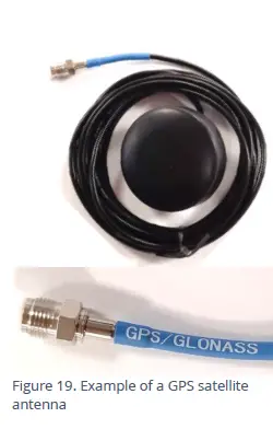
The connector will be labeled as ‘GPS TSYNC’ or ‘GPS CONNECTOR’ (or similar).
એન્ટેના જમીનની ઉપર અને આકાશ તરફની સીધી રેખા સાથે સ્થાપિત થયેલ હોવું જોઈએ (ભ્રમણ કરતા ઉપગ્રહોમાંથી રેડિયો સિગ્નલ લેવા).
Exampલે સ્થાનો છે:
- કેબિનેટ અથવા પોસ્ટ પર માઉન્ટ થયેલ સપાટી, ઉપર તરફ નિર્દેશ કરે છે.
- યોગ્ય રીતે મશીન કરેલ ચેમ્બરના ઢાંકણના ઉપરના ચહેરામાં જડિત, ફરીથી ઉપર તરફ નિર્દેશ કરે છે.
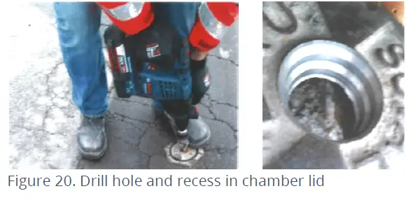
જ્યારે એન્ટેનાને ચેમ્બરના ઢાંકણામાં ફીટ કરવામાં આવે છે, ત્યારે એન્ટેનાના શરીરને સમાવવા માટે ઢાંકણને રિસેસ ડ્રિલ કરવું જરૂરી છે. એન્ટેનાને નુકસાનથી બચાવવા માટે વિરામ પૂરતો ઊંડો હોવો જોઈએ. એક માજીampમાર્ગદર્શન માટે જરૂરી પગલાંઓ નીચે મુજબ છે:
- પૂરા પાડવામાં આવેલ એન્ટેનાના પરિમાણો અને ચેમ્બરના ઢાંકણની જાડાઈ તપાસો. ઢાંકણમાં એન્ટેના કેવી રીતે માઉન્ટ કરવામાં આવશે તે ધ્યાનમાં લો. જો ઢાંકણું અપૂરતું જાડું હોય, તો ઊંડાઈ વધારવા માટે ઢાંકણની પાછળની બાજુએ પ્લેટ ફીટ કરવાની જરૂર પડી શકે છે.
- કેબલ અને કનેક્ટર પસાર થાય તે માટે પાથ બનાવવા માટે ઢાંકણમાંથી ડ્રિલ કરો.
- યોગ્ય કાઉન્ટરસિંક અથવા રિસેસ બનાવવા માટે વિશાળ કવાયતનો ઉપયોગ કરીને ઢાંકણમાં આંશિક રીતે ડ્રિલ કરો જેમાં એન્ટેનાનું શરીર ફિટ થઈ શકે.
 Thread antenna cable through hole, washer, and nut.
- Secure antenna to the lid using a washer and the supplied nut.
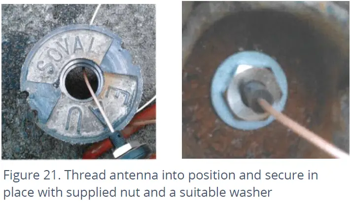
- If required, apply a resin epoxy such as Marine “Goop” to the perimeter of the antenna to help stabilize its position within the lid and to prevent water running onto the antenna cable. Do not cover the top of the antenna body as this may impair reception of satellite signals. Ensure all surfaces are clean and dry before applying the adhesive. Follow the adhesive manufacturer’s instructions.
- ખાતરી કરો કે એન્ટેના કેબલ ઇન્સ્ટોલેશન અને ઉપયોગ દરમિયાન ક્ષતિગ્રસ્ત ન થાય (દા.ત., ઢાંકણ દ્વારા).
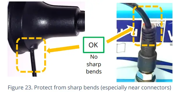
Connect the GPS Antenna to the GPS antenna connector on the logger. Do not over-tighten. For a reliable connection, apply silicon grease and O-ring to the connector prior to fitting, as detailed in section 5.18. Ensure there are no sharp bends in the antenna cable.
સાઇટ છોડતા પહેલા, એન્ટેના સ્થાન બરાબર છે અને સેટેલાઇટ સિગ્નલ પ્રાપ્ત થઈ રહ્યાં છે તેની ખાતરી કરવા માટે GPS પરીક્ષણ કરવા IDT નો ઉપયોગ કરો.
એન્ટેના (સેલ્યુલર કોમ્યુનિકેશન્સ)
An antenna should be selected to suit the available space in the chamber, allowing some space for it to be re-positioned (if required). Only use HWM-provided antenna with your logger, to ensure the radio interface meets approvals requirements (safety, etc). The Multilog 2 logger uses a metal “FME” style antenna connector.
એન્ટેનાને કનેક્ટ કરતા પહેલા, ખાતરી કરો કે કનેક્ટર શુષ્ક છે અને ગંદકી અને કાટમાળથી સાફ છે; ફસાયેલા ભેજ અથવા દૂષકો એન્ટેનાની કામગીરીને બગાડી શકે છે. જો જરૂરી હોય તો સાફ કરો.
જરૂરીયાત મુજબ કનેક્ટર પર SG M494 સિલિકોન ગ્રીસ લગાવો.
The antenna connector has an O-ring included for protection against water and moisture ingress; it acts as a seal. Check that the O-ring is present and undamaged.
Ensure that the connector and O-ring are dry and clear of dirt and debris. Clean carefully if necessary.
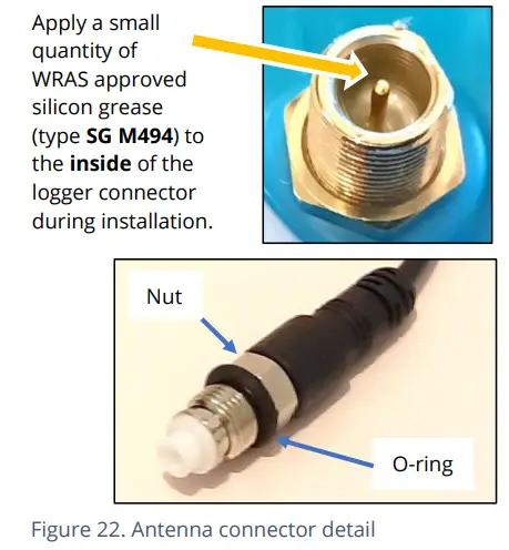
Insert the antenna connector into the logger connection and ensure it is fully home. Tighten the connector correctly; the nut on the antenna should be finger tight, plus 1/4 turn.
કેબલના છેડા પર અથવા એન્ટેના કેબલના રૂટીંગમાં કોઈ તીક્ષ્ણ વળાંક હોવો જોઈએ નહીં.
એન્ટેના કેબલને નુકસાન થવાના જોખમને ટાળવા માટે, તપાસો કે તેના પર કોઈ સાધન મૂકવામાં આવ્યું નથી. એ જ રીતે, કેબલને સ્થાને ફિક્સ કરતી કેબલ ટાઈ ખૂબ ચુસ્ત ન હોવી જોઈએ.
એન્ટેના ઇન્સ્ટોલેશનને ફિટ કરવા માટે વળેલું હોવું જોઈએ નહીં; જો તે ચેમ્બર માટે ખૂબ મોટું હોય, તો નાના પ્રકારના HWM માન્ય એન્ટેનાનો ઉપયોગ કરો.
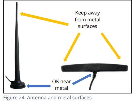
When positioning the antenna, ensure that the radiating end of the antenna does not touch or go close to a metal surface.
એન્ટેનાનું રેડિયેટિંગ તત્વ આદર્શ રીતે મુક્ત હવામાં (અવરોધોથી મુક્ત) હોવું જોઈએ.
એન્ટેનાને એવા સ્થાન પર મૂકવાનું ટાળવાનો પ્રયાસ કરો જ્યાં તે પૂર આવી શકે. જો આ અનિવાર્ય હોય, તો તેને જ્યાં ઓછામાં ઓછું જોખમ હોય ત્યાં મૂકો.
ગ્રાઉન્ડ લેવલની નીચે ચેમ્બરમાં ઇન્સ્ટોલ કરેલા સાધનો માટે, જો શક્ય હોય તો એન્ટેનાને જમીનના સ્તરથી ઉપર મૂકવો જોઈએ. જ્યાં આ શક્ય ન હોય, તેને ચેમ્બરની ટોચની નજીક મૂકો.
IDT નો ઉપયોગ એ તપાસવા માટે થવો જોઈએ કે લોગર સેલ્યુલર નેટવર્ક સાથે કનેક્ટ થઈ શકે છે અને એન્ટેના સાઇટ માટે શ્રેષ્ઠ સ્થિતિમાં છે.
- ઇન્સ્ટોલેશન માટે યોગ્ય એન્ટેના પસંદ કરો અને તેની પ્રારંભિક સ્થિતિ નક્કી કરો.
- ઉપયોગમાં લેવાતી નેટવર્ક ટેકનોલોજી નક્કી કરો અને પછી યોગ્ય સિગ્નલ ગુણવત્તા મર્યાદાનો ઉપયોગ કરો (IDT વપરાશકર્તા-માર્ગદર્શિકાનો સંદર્ભ લો).
- Perform Network Signal tests (with the chamber lid closed) to confirm the logger connects to the mobile network and find the best location of the antenna. Re-position if required.
- લોગર Da સાથે વાતચીત કરી શકે છે તેની ખાતરી કરવા માટે ટેસ્ટ કોલ્સ કરોtaGate server via the internet and (if required / available) SMS.
(આ પરીક્ષણો કરવા માટે IDT ના ઉપયોગની વિગતો IDT એપ્લિકેશન વપરાશકર્તા-માર્ગદર્શિકામાં પ્રદાન કરવામાં આવી છે).
Trouble-shoot a test-call failure if required, using the advice in the IDT app user-guide. Further information is given in the HWM Antenna Installation Guide (MAN-072-0001).
કેટલીક સામાન્ય સલાહ નીચે આપેલ છે:
મોનોપોલ એન્ટેના
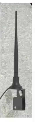
મોટાભાગના સ્થાપનો માટે, મોનોપોલ એન્ટેના સ્વીકાર્ય કામગીરી આપશે. ઇન્સ્ટોલેશન વિચારણાઓ:
- પૂરા પાડવામાં આવેલ દસ્તાવેજોમાં ચેતવણીઓ અનુસાર કોઈપણ ઇન્સ્ટોલેશન પ્રતિબંધોનું હંમેશા પાલન કરો.
- એન્ટેના માઉન્ટ કરવા માટે ઉપયોગમાં લેવા માટે ચુંબકીય આધાર ધરાવે છે.
શ્રેષ્ઠ કામગીરી માટે, એન્ટેનાને તેના આધાર પર "ગ્રાઉન્ડ પ્લેન" (મેટલ સપાટી)ની જરૂર છે. - મોટા ભૂગર્ભ ચેમ્બરમાં એન્ટેના સ્થાપિત કરતી વખતે તે સપાટીની નજીક સ્થિત હોવું જોઈએ.
- ખાતરી કરો કે કોઈપણ ચેમ્બરનું ઢાંકણું જ્યારે ખોલવામાં/બંધ કરવામાં આવે ત્યારે એન્ટેના અથવા કેબલમાં દખલ નહીં કરે.
- આ એન્ટેના ઊભી રીતે ધ્રુવીકૃત છે, તે હંમેશા ઊભી દિશામાં સ્થાપિત થયેલ હોવું જોઈએ.
- એન્ટેનાના રેડિએટિંગ તત્વને ક્યારેય વાળશો નહીં.
- એન્ટેનાને હાલની માર્કર પોસ્ટ પર માઉન્ટ થયેલ ઇન્સ્ટોલેશન કૌંસ સાથે પણ જોડી શકાય છે.
- જ્યાં એન્ટેનાને ચુંબક દ્વારા રાખવામાં આવે છે, ત્યાં ખાતરી કરો કે કોઈપણ કેબલનું વજન ચુંબકને વધુ પડતું લોડ કરતું નથી જેથી તેને સ્થાપિત સ્થાનથી અલગ કરી શકાય.
- કોઈપણ સાધનને એન્ટેના કનેક્ટર પર આરામ કરવાની મંજૂરી આપશો નહીં કારણ કે કનેક્ટર અથવા એન્ટેના કેબલને નુકસાન થઈ શકે છે.
અન્ય એન્ટેના વિકલ્પો અને વધારાના સ્થાપન માર્ગદર્શિકા માટે, આધાર પર ઉપલબ્ધ દસ્તાવેજોનો સંદર્ભ લો webપૃષ્ઠ: https://www.hwmglobal.com/antennas-support/
કૉલ ટેસ્ટ નિષ્ફળતાનું મુશ્કેલીનિવારણ
કૉલ ટેસ્ટ નિષ્ફળ થવાના ઘણા કારણો છે.
સહાય માટે HWM સપોર્ટને કૉલ કરતા પહેલા નીચેના મુદ્દાઓ તપાસવા જોઈએ:
| સંભવિત સમસ્યા | ઉકેલ |
| Network Busy due to excessive traffic. Commonly occurs around schools and at peak travel times. | થોડીવાર પછી ફરીથી ટેસ્ટ કરવાનો પ્રયાસ કરો. |
| તમારા સ્થાન પર નેટવર્ક સિગ્નલ ઉપલબ્ધ નથી. તમામ સેલ માસ્ટ ડેટા ટ્રાફિક વહન કરતા નથી | Relocate the logger to an area that has a data service or change to a different
network provider. |
| Network signal not strong enough.
For 2G and 3G networks, you need a CSQ (reported by the Call test) of at least 8 for reliable communications. For 4G networks, check the RSRP and RSRQ values are suitable, as described in the IDT user guide. |
જો શક્ય હોય તો એન્ટેનાને સ્થાનાંતરિત કરો અથવા વૈકલ્પિક એન્ટેના ગોઠવણીનો પ્રયાસ કરો. |
| APN સેટિંગ્સ ખોટી છે. | Check with your network operator that you have the correct settings for your SIM. |
જો તમે સંદેશાવ્યવહારમાં સમસ્યાઓનો અનુભવ કરવાનું ચાલુ રાખો છો, તો તમારે તમારા સ્થાનમાં નેટવર્ક કવરેજ તપાસવાની જરૂર પડી શકે છે.
મુશ્કેલીનિવારણ
કોઈપણ સમસ્યાઓએ સિસ્ટમના તમામ ભાગો (IDT, વપરાશકર્તા, લોગર, સેન્સર્સ, સેલ્યુલર નેટવર્ક અને સર્વર) ને ધ્યાનમાં લેવું જોઈએ.
સામાન્ય તપાસો:
સાઇટની મુલાકાત દરમિયાન કરવામાં આવનારી પ્રારંભિક તપાસમાં નીચેનાનો સમાવેશ થાય છે:
- તમે જે IDT વર્ઝનનો ઉપયોગ કરી રહ્યા છો (મોબાઇલ ડિવાઇસ માટે IDT એપ / Windows PC માટે IDT) તે તમે ઉપયોગ કરી રહ્યા છો તે સુવિધાઓ અને સેન્સર્સને સપોર્ટ કરે છે કે નહીં તે તપાસો; વિભાગ 8 નો સંદર્ભ લો.
- તપાસો કે IDT ના નવીનતમ સંસ્કરણનો ઉપયોગ કરવામાં આવી રહ્યો છે.
- તપાસો કે જે લોગરનો ઉપયોગ કરવામાં આવી રહ્યો છે તેમાં નવીનતમ સૉફ્ટવેર છે (જો જરૂરી હોય તો IDT અપગ્રેડ કરવાની ઑફર કરશે).
- બેટરી વોલ તપાસોtagલોગરનું e સારું છે (IDT હાર્ડવેર ટેસ્ટનો ઉપયોગ કરીને).
- તપાસો કે સેન્સર અને લોગર વચ્ચેના કેબલ અને કનેક્ટર્સ બરાબર સ્થિતિમાં છે, જેમાં કોઈ નુકસાન કે પાણી પ્રવેશતું નથી.
લોગર IDT સાથે વાતચીત કરવામાં સક્ષમ હોય તેવું લાગતું નથી:
- Check the communications path from the IDT host device to the logger is complete.(See section 2.8.)
- If using the direct cable connection method with IDT (PC), the logger may have shut down the connection to IDT due to is not being used for several minutes. Re-read the logger settings into IDT. Any previously unsaved settings will have been lost.
- જો તમે IDT એપ્લિકેશનનો ઉપયોગ કરી રહ્યા છો, તો કેબલનો ઉપયોગ કરવાની પરવાનગી સમાપ્ત થઈ ગઈ હશે. પ્રોગ્રામિંગ કેબલના USB-A છેડાને અલગ કરો અને થોડી સેકંડ પછી ફરીથી જોડો. કેબલનો ઉપયોગ કરવાની પરવાનગી આપો અને પછી લોગર સેટિંગ્સને IDT માં ફરીથી વાંચો. અગાઉ સાચવેલ ન હોય તેવી કોઈપણ સેટિંગ્સ ખોવાઈ જશે.
લોગરનો ડેટા સર્વર પર દેખાતો નથી:
- મોબાઇલ ડેટા નેટવર્કને ઍક્સેસ કરવા માટે SIM કાર્ડ માટે સેટિંગ્સ તપાસો.
- ખાતરી કરો કે લોગર સાચા ડેટા ગંતવ્યનો ઉપયોગ કરે છે URL અને તમારા સર્વર માટે પોર્ટ નંબર.
- ચેક કૉલ-ઇન સમય સેટ કરવામાં આવ્યો છે.
- તપાસો કે એન્ટેના જોડાયેલ છે અને બરાબર સ્થિતિમાં છે.
- સિગ્નલની ગુણવત્તા તપાસો અને તાકાત પરિમાણો યોગ્ય છે. જો જરૂરી હોય તો એન્ટેનાને ફરીથી શોધો અથવા વૈકલ્પિક પ્રકારના એન્ટેનાનો પ્રયાસ કરો.
- કૉલ ટેસ્ટ કરો અને ઓકે કન્ફર્મ કરો.
- ખાતરી કરો કે તમારું સર્વર ડેટા પ્રાપ્ત કરવા અને પ્રસ્તુત કરવા માટે યોગ્ય રીતે ગોઠવેલ છે.
જાળવણી, સેવા અને સમારકામ
Unauthorized servicing will void the warranty and any potential liability for
HWM-વોટર લિ.
સફાઈ
સફાઈ માટે લાગુ પડતી સલામતી ચેતવણીઓની નોંધ લો. હળવા ક્લિનિંગ સોલ્યુશન અને એડનો ઉપયોગ કરીને યુનિટને સાફ કરી શકાય છેamp નરમ કાપડ. કનેક્ટર્સને હંમેશા ગંદકી અને ભેજથી મુક્ત રાખો.
બદલી શકાય તેવા ભાગો
એન્ટેના
HWM દ્વારા ભલામણ કરેલ અને પ્રદાન કરેલ એન્ટેનાનો જ ઉપયોગ કરો.
એન્ટેના વિકલ્પો અને ઓર્ડર કરવા માટેના ભાગ-નંબરોની વિગતો માટે, નીચેની લિંકનો સંદર્ભ લો: https://www.hwmglobal.com/antennas-support/ (અથવા તમારા HWM પ્રતિનિધિની સલાહ લો).
બેટરીઓ
- HWM દ્વારા ભલામણ કરેલ અને પ્રદાન કરેલ બેટરી અને ભાગોનો જ ઉપયોગ કરો.
- બેટરી માત્ર HWM માન્ય સેવા કેન્દ્ર અથવા સંબંધિત રીતે પ્રશિક્ષિત ટેકનિશિયન દ્વારા બદલી શકાય છે. જો જરૂરી હોય તો વધુ વિગતો માટે તમારા HWM પ્રતિનિધિનો સંપર્ક કરો.
- Batteries can be returned to HWM for disposal. To arrange the return, complete the on-line RMA (Returned Materials Authorisation) form: https://www.hwmglobal.com/hwm-rma/
- પેકિંગ આવશ્યકતાઓની માર્ગદર્શિકા માટે સલામતી ચેતવણીઓ અને મંજૂરીઓની માહિતીનો સંદર્ભ લો.
સિમ કાર્ડ
- સિમ-કાર્ડ HWM માન્ય સેવા કેન્દ્ર અથવા સંબંધિત તાલીમ પામેલા ટેકનિશિયન દ્વારા બદલી શકાય છે.
- HWM દ્વારા ભલામણ કરેલ અને પ્રદાન કરેલ ઉપભોજ્ય ભાગોનો જ ઉપયોગ કરો.
સેવા અથવા સમારકામ માટે ઉત્પાદનનું વળતર
તપાસ અથવા સમારકામ માટે ઉત્પાદન પરત કરતી વખતે, ઉત્પાદન શા માટે પરત કરવામાં આવી રહ્યું છે તે દસ્તાવેજ કરવા માટે તમારા વિતરકની સૂચનાઓનું પાલન કરવાની ખાતરી કરો અને સંપર્ક વિગતો પ્રદાન કરો.
જો HWM પર પાછા ફરો, તો આ ઓન-લાઇન RMA ફોર્મ ભરીને કરી શકાય છે: https://www.hwmglobal.com/hwm-rma/
શિપિંગ કરતા પહેલા, સાધનોને શિપિંગ મોડમાં મૂકો (સૂચનાઓ માટે IDT વપરાશકર્તા-માર્ગદર્શિકાનો સંદર્ભ લો). પેકિંગ આવશ્યકતાઓની માર્ગદર્શિકા માટે સલામતી ચેતવણીઓ અને મંજૂરીઓની માહિતીનો સંદર્ભ લો.
જો ગંદી હોય, તો ખાતરી કરો કે એકમ હળવા ક્લિનિંગ સોલ્યુશન અને સોફ્ટ બ્રશથી સાફ કરવામાં આવે છે, જંતુમુક્ત અને શિપમેન્ટ પહેલાં સૂકવવામાં આવે છે.
APPENDIX 1: SYSTEMS AND FEATURES REQUIRING IDT (PC)
Historically, setup of Multilog2 loggers was undertaken using the IDT (PC/Windows) tool. Setup of most Multilog2 logger functions for Pressure and Flow channels and the most commonly used alarm types has recently been introduced to the IDT (mobile app) tool. However, the IDT (mobile app) does not yet support some situations.
The following logger types require IDT (PC) for their entire setup:
- WL/*/*/* Multilog2 logger device (models for use in WITS systems). Refer to the IDT (PC) user-guide for most settings. Additional information for WL series models can be found in the following user-guide: MAN-147-0017 (Supplement for models supporting WITS protocol).
- RDL6*LF/* Multilog (original) logger devices.
નીચેના લોગર/સેન્સર સંયોજનોને સેટઅપ માટે IDT (PC) ની જરૂર પડે છે:
- Multilog2 using a SonicSens2 sensor.
- Multilog2 using a SonicSens3 sensor.
- Multilog2 using a RS485/MODBUS sensor.
- Multilog2 using an SDI-12 sensor.
- Multilog2 using a Hydrophone or LNS (Leak-Noise Sensor).
- Multilog2 using a GPS Satellite (for either location or Time-sync).
નીચેની લોગર સુવિધાઓને સેટઅપ માટે IDT (PC) ની જરૂર પડે છે:
- લોગર અથવા જોડાયેલ સેન્સરના ફર્મવેરનું અપડેટ.
- ઝડપી લોગીંગ સુવિધાઓ (પ્રેશર ક્ષણિક, ઉન્નત નેટવર્ક લોગીંગ).
- પ્રવાહ દર (જ્યારે પ્રવાહ વેગ, ચેનલ ઊંડાઈ, ચેનલ ભૂમિતિ પરથી ગણતરી કરવામાં આવે છે).
- પ્રોfile એલાર્મ.
- Tampએલાર્મ.
- GPS functions, including GeoFence Alarm.
APPENDIX 2: COMMUNICATING TO LOGGER VIA SMS
નોંધ: This facility may not be available on your logger, depending on the SIM card fitted. Some SIM cards or networks or service providers do not have SMS messaging available. (See also section 1.4).
- Applying a ‘Modem Activation Key’ (See Figure 25) to the 10-pin Comms interface for a period of 10 seconds will activate the logger’s cellular communications modem for a period of 5 minutes. This will allow an installer to send SMS (text) messages from a mobile phone and for the logger to respond.
(There is an alternative way to do this using IDT). - ચેમ્બર અથવા કેબિનેટ બંધ કરો જેથી બધું તેની અંતિમ સ્થિતિમાં હોય.
- Using a standard mobile phone, send a text message to the SMS number of the logger (check the logger label), including the international dialing code if needed.
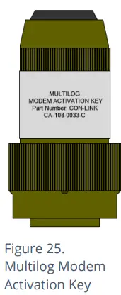
- ટેક્સ્ટ સંદેશ TTTT# વાંચવો જોઈએ
થોડીક સેકન્ડ/મિનિટ પછી (નેટવર્ક ઓપરેટર પર આધાર રાખીને) લોગર તમને તેની વર્તમાન સ્થિતિની વિગતો સાથે એક સંદેશ મોકલશે.
- Exampલોગર તરફથી પ્રતિસાદ:
TTTT138-002 V01.70CSQ:1010.9VyouridRT hh:mm ss dd-mm-yy …
પરત આવેલ સંદેશને સમજવા માટે, કૃપા કરીને નીચેના કોષ્ટકનો સંદર્ભ લો:
| સંદેશ | વર્ણન |
| TTTT | Original command text without # |
| 138-002 | Logger type number |
| V01.00 | Firmware version in Logger. |
| CSQ: nn | Signal strength nn (nn = 6 to 30) |
| 10.9 વી | સંચાલન ભાગtage |
| yourid | Your Logger ID |
| RT hh:mm ss dd-mm-yy | Real Time Clock setting |
| ST hh:mm ss dd-mm-yy | First Time the logger was started |
| LR hh:mm ss dd-mm-yy | Last Time the logger was re-started |
| Ch1 (A) 0029.0 | Channel 1 29.0 units |
| Ch2 (A) 0002.2 | Channel 2 2.2 pulses/sec |
If the CSQ: value in the message is OK, then the installation is complete. The logger will automatically go back to sleep after 10 minutes.
SMS નેટવર્કમાં વિલંબ થઈ શકે છે, તેથી તમારા સંદેશનો પ્રતિસાદ તાત્કાલિક ન હોઈ શકે. જો તમને 10 મિનિટમાં કોઈ જવાબ ન મળ્યો હોય, તો ચેમ્બર ફરીથી ખોલો અને મોડેમ ડાયગ્નોસ્ટિકનો ઉપયોગ કરીને તમારી જાતને એક પરીક્ષણ SMS મોકલો. જો આ થઈ જાય, તો પછી એન્ટેનાનું સ્થાન બહેતર બનાવો અને ફરી પ્રયાસ કરો.
નોંધ: Some Roaming SIM cards do not accept incoming text messages.
Check with your service provider if you are unsure.
- ફ્લુઇડ કન્ઝર્વેશન સિસ્ટમ્સ 1960 ઓલ્ડ ગેટ્સબર્ગ રોડ સ્યુટ 150
- સ્ટેટ કોલેજ PA, 16803 800-531-5465
- www.fluidconservation.com
FAQ
Q: Where can I find additional support for Multilog 2?
A: For further assistance not covered in the manual, contact the HWM Technical Support team at +44 (0) 1633 489479 or email cservice@hwm-water.com.
દસ્તાવેજો / સંસાધનો
 |
FCS Multilog2 Multi Channel Data Logger [પીડીએફ] વપરાશકર્તા માર્ગદર્શિકા ML- - -, PT- - -, EL- - -, Multilog2 Multi Channel Data Logger, Multilog2, Multi Channel Data Logger, Data Logger, Logger |