Robot XF(A5) V2.0.5 GCU Private Protocol
Specifications
- Document Version: V2.0.5
- Protocol Version: V0.1
Product Information
The GCU (Generic Control Unit) operates on a private protocol and offers various features and improvements as per the revision history:
Features:
- UART baudrate changes into self-adaptive
- Add TCP Server mode in Network communication
- Add protocol version into data package
- Enhancements in data frames for both host computer and GCU
- Command & Feedback improvements
- Example data package renewal
Product Usage Instructions
Main Data Frame from Host Computer
- Add desired Euler angle and desired relative angle into roll/pitch/yaw control value (byte 5~10)
- Add control quantities effectiveness (bit B2) into statue (byte 11)
Main Data Frame from GCU
- Add FPV mode and Euler angle control mode into pod statue (byte 5)
- Delete exposure mode (bit B11) from camera statue (byte 6~7)
Sub Data Frame from Host Computer
- Delete distance from Home (byte 57~60)
- Add relative height (byte 57~60)
Revision History
| Date | Document Version | Protocol Version |
| 2023.06.19 | V2.0 | – |
| Date | Document Version | Protocol Version |
| 2023.08.09
1. UART baudrate cha |
V2.0.1
nges into self-adaptive. Ad |
V0.0
d TCP Server mode in |
- UART baudrate changes into self-adaptive. Add TCP Server mode in Network communication. [P1]
- Add protocol version into data package. Correct the mistake of header in package from GCU. [P2]
- Main data frame from host computer:
- Add desired Euler angle and desired relative angle into roll/pitch/yaw control value (byte 5~10); [P3]
- Add control quantites effectiveness (bit B2) into statue (byte 11). [P3]
- Sub data frame from host computer:
- Delete distance from Home (byte 57~60); [P4]
- Add relative height (byte 57~60) . [P4]
- Main data frame from GCU:
- Add FPV mode and Euler angle control mode into pod statue (byte 5); [P5]
- Delete exposure mode (bit B11) from camera statue (byte 6~7). [P5]
- Sub data frame from GCU:
- Delete content of byte 59~61; [P6]
- Add current zoom rate of camera 1 (byte 59~60) and camera 2 (byte 61~62). [P6]
- Command & Feedback:
- Add description of null command; [P7]
- Add command of FPV mode, Euler angle control mode, external tracking mode and OSD; [P7~P9]
- Detail description of gaze mode; [P8]
- Modify parameters of shutter, record, focus, palette and Night vision command. [P8~P9]
- Renew example data package. [P11~P16]
| Date | Document Version | Protocol Version |
| 2023.10.12 | V2.0.2 | V0.1 |
- Add explanation on byte order of the protocol. [P2]
- Main data frame from host computer:
- Add coordinate system definition into description of absolute roll, pitch and yaw angle of carrier (byte 12~17). [P3]
- Main data frame from GCU:
- Add lighting statue (bit B10) into camera statue (bit B10). [P5]
- Correct the mistake of coordinate axis direction (“upward as positive”→”downward as positive”) of vertical target-missing (byte 10~11). [P5]
- Add value range into description of X-ward/ Y-ward target-missing (byte 8~11). [P5]
- Add coordinate system definition and rotate order into description of X-axis/ Y-axis/ Z-axis absolute angular velocity of camera (byte 24~29). [P5]
- Command & Feedback:
- Modify explanations on control values in descriptions of FPV mode, head lock mode and head follow mode. [P7]
- Correct the mistake of false feedback (“0x015 0x01″→”0x15 0x01”) of gaze mode (geo-coordinates guide). [P8]
- Add coordinates of target frame’s top-left corner and lower-right corner into description of track mode. [P8]
- Add coordinates of screen’s top-left corner and lower-right corner in description of click to aim command. [P8]
- Add target-missing of screen’s center, top-left corner and lower-right corner in description of external track mode. [P9]
- Add appendix 1: example of transformation of data frame from host computer. [P12]
- Add appendix 2: definition of carrier’s coordinate system. [P13]
- Add appendix 3: definition of camera’s coordinate system and rotate order. [P14]
- Add appendix5: GPS time & UTC conversion function.[P21]
| Date | Document Version | Protocol Version |
| 2024.06.20 | V2.0.5 | V0.1 |
- Main Data Frame from Host Computer:
- Add explaination about control value effectivity (bit B2) in description of statue (byte 11) . [P3]
- Main Data Frame from GCU:
- Rename FPV to angle control 1 and add angle control 2 in pod operating mode (byte 5). [P5]
- Rename camera statue(byte 6~7) to pod statue. [P5]
- Sub Data Frame from GCU:
- Add error code (byte 41~42). [P6]
- Add thermal camera statue (byte 63). [P6]
- Add camera statue (byte 64~65). [P7]
- Add time zone (byte 66). [P7]
- Command & Feedback:
- Add commands of OSD coordinate, image auto reverse and time zone setting. [P8]
- Modify descriptions of angle control 1 (original FPV), head follow and Euler angle control. [P8]
- Add command of angle control 2. [P10]
- Modify the parameter range of palatte ([0,100]->[0,10]). [P11]
- Add commands of area temperature measurement, temperature alert, isotherm and spot temperature measurement. [P11~P12]
- Add function of switching to specified mode in pic-in-pic. [P12]
- Add commands of target detection and zoom camera digital zoom. [P13]
- Add Appendix 2: Example of Transformation of Data Frame from GCU. [P16~P18]
- Renew Appendix 5: Example Data Package. [P20~P28]
- Add Appendix 7: Pod Code. [P30]
Port Configuration
UART Configuration
- UART level: TTL
- Data bits: 8
- Stop bits: 1
- Parity: None
- Communication mode: Full duplex
- Baudrate: 115200, 250000, 500000 and 1000000.
- Communication frequency: The recommended communication frequency range is 30~50Hz. The higher the frequency is, the better the effect of controlling is. There should not be too low frequency or data stop. There should not be BUS idle in one data package.
Network Configuration
- UDP mode: The source port is 2337 and the default destination is the LAN broadcast address. The target port is 2338.
- TCP Server mode: The opposite end should be set to TCP Clint mode.
The remote IP address should be the same as GCU, and the remote port should be 2332.
Summary
- The communication uses Q&A mode. The host computer transmits data package firstly. After receiving the correct package, the GCU returns its package. A complete data package is made up of protocol header, package length, main data frame, sub data frame, command/feedback and CRC data.
- The length of the package is S bytes. The length of command / feedback part is variable.
- The command / feedback part includes order and parameter. Different order maps different parameter. Details as per chapter Data Frame in this document.
- The GCU will execute only once while continuously receiving commands with same order (even if the parameters are different). To trigger one same function, the data packages should be separated by a package with null command (Except External track command).
The structure of the data package is shown as below.
| Section | Byte(s) | Description | Data Type | Details |
|---|---|---|---|---|
| From Host Computer | ||||
| Header | 0 | Main Data | U16 | |
| 1 | Sub Data | U8 | ||
| Length and Version | 2–3 | Length & Version Info | ||
| Frame Data | 4 | Frame | ||
| Frame Data | 5–36 | Main Data | 32 bytes | |
| Frame Data | 37–68 | Sub Data | 32 bytes | |
| From GCU | ||||
| Header | 0 | 0x8A | ||
| 1 | 0x5E | |||
| Length and Version | 2–3 | Length & Version Info | ||
| Frame Data | 4 | Frame | ||
| Frame Data | 5–36 | Main Data | 32 bytes | |
| Frame Data | 37–68 | Sub Data | 32 bytes | |
| Command Data | 69–S-3 | Command (Variable Length) | ||
| Feedback Data | 69–S-3 | Feedback (Variable Length) | ||
| CRC High Byte | S-2 | CRC High Byte | U16 | |
| CRC Low Byte | S-1 | CRC Low Byte | U16 |
- The data checked by CRC is Byte 0~S-3.
- This protocol uses little-endian byte order (except CRC).
Data Frame
Main Data Frame from Host Computer
| Byte(s) | Content | Description | Data Type | Details |
|---|---|---|---|---|
| 5–6 | Other modes, Zoom rate (deg/s) | When the control value is desired Euler angle. | Resolution: 0.01 deg; Range: 8000 to 18000 | |
| 7–8 | Pitch control value | When the control value is desired relative angle between pod and carrier. | S16 | Resolution: 0.01 deg; Range: [-18000, 18000] |
| 9–10 | Yaw control value | Control value for yaw angle. | S16 | Resolution: 0.01 deg; Range: [-18000, 18000] |
| B7–B3 | Reserved | Reserved bits. | These bits are 0 | |
| B2 | Control value validity | 0 – Control value invalid; 1 – Control value valid. | U8 | |
| B1 | Reserved | This bit is 0 | ||
| B0 | Carrier’s INS validity | 0 – Carrier’s INS invalid; 1 – Carrier’s INS valid. | U8 | |
| 11 | Status | Indicates if control value is valid. | U8 | 0 – Invalid, 1 – Valid |
| 12–13 | Absolute roll angle of carrier | Absolute roll angle of carrier in Euler angle. | S16 | Resolution: 0.01 deg; Range: [-9000, 9000] |
| 14–15 | Absolute pitch angle of carrier | Absolute pitch angle of carrier in Euler angle. | S16 | Resolution: 0.01 deg; Range: [-9000, 9000] |
| 16–17 | Absolute yaw angle of carrier | Absolute yaw angle of carrier in Euler angle. | U16 | Resolution: 0.01 deg; Range: [0, 36000] |
| 18–19 | Northward acceleration of carrier | Northward acceleration of the carrier. | S16 | Resolution: 0.01 m/s²; Northwards is positive |
| 20–21 | Eastward acceleration of carrier | Eastward acceleration of the carrier. | S16 | Resolution: 0.01 m/s²; Eastwards is positive |
| 22–23 | Upward acceleration of carrier | Upward acceleration of the carrier. | S16 | Resolution: 0.01 m/s²; Upwards is positive |
| 24–25 | Northward velocity of carrier | Northward velocity of the carrier. | S16 | Resolution: 0.1 m/s; Northwards is positive |
| 26–27 | Eastward velocity of carrier | Eastward velocity of the carrier. | S16 | Resolution: 0.1 m/s; Eastwards is positive |
| 28–29 | Upward velocity of carrier | Upward velocity of the carrier. | S16 | Resolution: 0.1 m/s; Upwards is positive |
| 30 | Request code of sub-frame | Code for requested sub-frame from GCU. | U8 | |
| 31–36 | Reserved | Reserved bytes. | ||
| 37 | Header of requested sub-data frame from GCU | GCU sub-frame request header (Ox00). | U8 |
Byte 12~29 are very important. Incorrect data will cause error of pod altitude calculation
Sub Data Frame from Host Computer
| Byte(s) | Content | Description | Data Type | Resolution |
|---|---|---|---|---|
| 37 | 0x01 | Header | U8 | |
| 38–41 | Longitude of carrier | Longitude of the carrier | S32 | Resolution: 1e-7 deg |
| 42–45 | Latitude of carrier | Latitude of the carrier | S32 | Resolution: 1e-7 deg |
| 46–49 | Altitude of carrier | Altitude of the carrier | S32 | Resolution: 1 mm |
| 50 | Available satellites | Number of available satellites | U8 | |
| 51–54 | GNSS microsecond | GNSS microsecond | U32 | |
| 55–56 | GNSS week | GNSS week | S16 | |
| 57–60 | Relative height | Relative height | S32 | Resolution: 1 mm |
| 61–68 | Reserved | Reserved bytes | Ox00 |
Byte 37~68 are all 0x00 if there is no sub frame data.
Main Data Frame from GCU
| Byte(s) | Content | Description | Data Type | Resolution |
|---|---|---|---|---|
| 5 | Pod operating mode | Mode of operation for the pod | U8 | Possible values: 0x10 to 0x1C (listed below) |
| 6–7 | Pod statue | Status of the pod | U16 | B15–B13: Reserved. B12: Power-on status. B10: Lighting. B9: Night vision. B8: Ranging. B7: Coordinate validity. B0: Tracking status. |
| 8–9 | Horizontal target-missing | Horizontal target position relative to center of screen | S16 | Range: [-1000, 1000]; Rightward positive |
| 10–11 | Vertical target-missing | Vertical target position relative to center of screen | S16 | Range: [-1000, 1000]; Downward positive |
| 12–13 | X-axis relative angle of camera | Relative X-axis angle of the camera | S16 | Range: [-18000, 18000]; Resolution: 0.01 deg |
| 14–15 | Y-axis relative angle of camera | Relative Y-axis angle of the camera | S16 | Range: [-9000, 9000]; Resolution: 0.01 deg |
| 16–17 | Z-axis relative angle of camera | Relative Z-axis angle of the camera | S16 | Range: [-18000, 18000]; Resolution: 0.01 deg |
| 18–19 | Absolute roll angle of camera | Absolute roll angle of the camera (Euler angle) | S16 | Range: [-9000, 9000]; Resolution: 0.01 deg |
| 20–21 | Absolute pitch angle of camera | Absolute pitch angle of the camera (Euler angle) | S16 | Range: [-18000, 18000]; Resolution: 0.01 deg |
| 22–23 | Absolute yaw angle of camera | Absolute yaw angle of the camera (Euler angle) | U16 | Range: [0, 36000]; Resolution: 0.01 deg |
| 24–25 | X-axis absolute angular velocity of camera | X-axis angular velocity of the camera | S16 | Resolution: 0.01 deg/s |
| 26–27 | Y-axis absolute angular velocity of camera | Y-axis angular velocity of the camera | S16 | Resolution: 0.01 deg/s |
| 28–29 | Z-axis absolute angular velocity of camera | Z-axis angular velocity of the camera | S16 | Resolution: 0.01 deg/s |
| 30–36 | Reserved | Reserved bytes |
Pod Operating Mode Possible Values:
- 0x10 – Angle control 1
- 0x11 – Head lock
- 0x12 – Head follow
- 0x13 – Orthoview
- 0x14 – Euler angle control mode
- 0x16 – Gaze
- 0x17 – Track
- 0x1C – Angle control 2
Sub Data Frame from GCU
| Byte(s) | Content | Description | Data Type | Resolution |
|---|---|---|---|---|
| 37 | 0x01 | Header | U8 | |
| 38 | Hardware version | Version of hardware | U8 | |
| 39 | Firmware version | Version of firmware | U8 | |
| 40 | Pod code | Code for the pod | U8 | Details as per Appendix 7 |
| 41–42 | Error code anomaly | Error codes for any anomalies | S32 | |
| 43–46 | Distance from target | Measurement of distance from the target | S32 | Resolution: 0.1 m (Invalid if -1m or 0m) |
| 47–50 | Longitude of target | Longitude of the target | S32 | Resolution: 1e-7 deg |
| 51–54 | Latitude of target | Latitude of the target | S32 | Resolution: 1e-7 deg |
| 55–58 | Altitude of target | Altitude of the target | S32 | Resolution: 1 mm |
| 59–60 | Current zoom rate of camera | Current zoom rate of the camera (visible-light camera) | U16 | Resolution: 0.1x |
| 61–62 | Current zoom rate of camera | Current zoom rate of the camera (thermal camera) | U16 | Resolution: 0.1x |
| 63 | Thermal camera statue | Status of thermal camera | U8 | B7: Temperature measurement, B6: Area temperature, etc. |
Thermal Camera Status (Byte 63)
- B7: 0 – Temperature measurement unavailable; 1 – Temperature measurement available
- B6: 0 – Area temperature measurement off; 1 – Area temperature measurement on
- B5: 0 – Temperature alert off; 1 – Temperature alert on
- B4: 0 – Isotherm off; 1 – Isotherm on
- B3: 0 – Spot temperature measurement off; 1 – Spot temperature measurement on
- B2: Reserved
- B1: High temperature alert
- B0: Low-temperature alert
| Byte(s) | Content | Description | Data Type | Resolution |
|---|---|---|---|---|
| 64–65 | Camera statue | Status of the camera | U16 | B15: Target detection on/off; B14: Digital zoom on/off, etc. |
| 66 | Time zone | Time zone setting | U8 | |
| 67–68 | Reserved | Reserved for future use | – |
Camera Statue (Byte 64-65)
- B15: 0 – Target detection off; 1 – Target detection on
- B14: 0 – Digital zoom off; 1 – Digital zoom on
- B13: 0 – OSD (On-Screen Display) off; 1 – OSD on
- B12: 0 – OSD displays carrier’s coordinate; 1 – OSD displays target’s coordinate
- B11: 0 – Image auto reverse on; 1 – Image auto reverse off
- B10–B5: Reserved
- B4: 0 – Not recording; 1 – Recording
- B3: Reserved
- B2–B0: uint_t – Pic-in-pic mode
Byte 37~68 are all 0x00 while an illegal sub frame header is requested.
Command & Feedback
| Function | Code | Description | Success | Fail |
|---|---|---|---|---|
| Null | 0x00 | Separates commands with the same order | 0x01 0x00 | 0x01 0x01 |
| Calibration | 0x01 | Pod should remain static while calibrating, lasting a few seconds. | 0x01 0x00 | 0x01 0x01 |
| Order Parm | 0x00 | |||
| Feedback | 0x03 | Feedback during operation | 0x03 0x00 | 0x03 0x01 |
| OSD | 0x06 | OSD displays coordinate system: 0x00 for Carrier’s, 0x01 for Target’s | 0x06 0x00 | 0x06 0x01 |
| Coordinate | 0x07 | 0x07 0x00 | 0x07 0x01 | |
| Image auto reverse | 0x08 | Controls the image auto reverse. 0x00 for on, 0x01 for off | 0x08 0x00 | 0x08 0x01 |
| Time zone | 0x10 | Controls time zone setting | 0x10 0x00 | 0x10 0x01 |
| Angle control 1 | 0x10 | Controls the angle of the pod (specific control values needed). | 0x10 0x00 | 0x10 0x01 |
| Head lock | 0x11 | Returns pod to neutral position without switching operation mode (lock mode). | 0x11 0x00 | 0x11 0x01 |
| Head follow | 0x12 | Returns pod to neutral yaw position while following target or heading. | 0x12 0x00 | 0x12 0x01 |
| Orthoview mode | 0x13 | Returns neutral yaw position without switching operation mode. | N/A | N/A |
| Track mode | 0x14 | Pod returns neutral position and exits tracking while tracking the target. | N/A | N/A |
| FPV Mode | 0x15 | No response from the pod in FPV mode. | N/A | N/A |
| Euler angle control | 0x16 | Pod locks Euler angles and does not respond to control. | N/A | N/A |
| Gaze Mode | 0x17 | Pod does not respond to control in Gaze mode. | N/A | N/A |
Descriptions of Specific Modes:
- Head Lock & Head Follow Mode: The pod maintains its neutral position (yaw or pitch) without changing modes.
- Orthoview Mode: Only yaw angle is returned, and the pod doesn’t switch modes.
- Track Mode: Neutral positions for both pitch and yaw are returned while exiting tracking mode.
- FPV Mode, Euler Angle Control, and Gaze Mode: The pod does not respond in these modes, as specified.
| Function | Code | Description | Success | Fail |
|---|---|---|---|---|
| Orthoview | 0x13 | Desired Euler angles are provided, and the pod locks its current Euler angles when the control values are invalid. | 0x13 0x00 | 0x13 0x01 |
| Euler Angle Control | 0x14 | Desired Euler angles for controlling pitch and yaw. | 0x14 0x00 | 0x14 0x01 |
| Gaze (Geo-coordinates Guide) | 0x15 | The pod is directed to a specific point of interest using its geographical coordinates (longitude, latitude, altitude) provided in the control values. | 0x15 0x00 | 0x15 0x01 |
| Gaze (Geo-coordinates Lock) | 0x16 | The pod locks its position based on geographical coordinates (longitude, latitude, altitude) and maintains a fixed gaze. Requires valid carrier’s INS data. | 0x16 0x00 | 0x16 0x01 |
| Track | 0x17 | Track mode is activated by providing tracking coordinates and setting the control values for tracking a target. | 0x17 0x00 | 0x17 NN |
Descriptions of Specific Functions:
- Orthoview: Locks the pod’s current Euler angles when control values are invalid.
- Euler Angle Control: Control the pod’s Euler angles (pitch, yaw) to desired positions.
- Gaze (Geo-coordinates Guide): Direct the pod towards a specific geographical point using its coordinates (longitude, latitude, altitude). Control values (PP, QQ, RR) are provided for accurate positioning.
- Gaze (Geo-coordinates Lock): Locks the pod’s gaze on a geographical point and tracks its current position. Requires valid INS (Inertial Navigation System) data from the carrier.
- Track: Starts or exits tracking a target by specifying coordinates (XO, YO, X1, Y1). The coordinates define the horizontal and vertical areas in the target frame, with the top-left corner as the origin.
Notes:
- For Track, “OX” and “YO” values are coordinates that represent the top-left and bottom-right corners of the target’s frame on the screen. These are defined in U16 values, where 0 is the origin, and positive values move rightwards (X-axis) and downwards (Y-axis).
- Gaze (Geo-coordinates): The pod needs valid carrier INS data to function properly in these modes.
The KK/NN(U8) is ordinal of operation triggered/failed cameras. B7~BO correspond camera 8~1. A certain bit being 1 means its corresponding camera being tagged. For example, 0x03 (00000011) means camera 1 and camera 2. Camera 1 is visible-light zoom camera by default and camera 2 is thermal camera by default.
| Function | Code | Description | Success | Fail |
|---|---|---|---|---|
| Click to Aim | 0x1A | The pod aims at a target based on provided horizontal (XO) and vertical (YO) coordinates. Coordinates are in U16, where (0,0) is the top-left of the screen and (10000,10000) is the bottom-right. | 0x1A 0x00 | 0x1A NN |
| External Track | 0x1B | The pod tracks the target based on horizontal and vertical missdistance values (PP, WW). These values indicate the target’s location relative to the center of the screen. | 0x1B 0x00 | 0x1B NN |
| Angle Control 2 | 0x1C | The pod adjusts its relative angles to the carrier, following the carrier while the control values are invalid. | 0x1C 0x00 | 0x1C 0x01 |
| Shutter (Record Start) | 0x20 | Starts recording. | 0x20 0x00 | 0x20 0x01 |
| Shutter (Stop Recording) | 0x21 | Stops recording. | 0x21 0x00 | 0x21 0x01 |
| Zoom In Continuously | 0x22 | Continuously zoom in. | 0x22 0x00 | 0x22 NN |
| Zoom Out Continuously | 0x23 | Continuously zoom out. | 0x23 0x00 | 0x23 NN |
| Zoom Stop | 0x24 | Stops the zoom function. | 0x24 0x00 | 0x24 NN |
Descriptions of Specific Functions:
- Click to Aim (0x1A): The pod aims at a specific target based on coordinates. These coordinates are provided as U16 values, where (0,0) is the top-left and (10000,10000) is the bottom-right corner of the screen.
- External Track (0x1B): The pod tracks the target based on the missdistance values (PP and WW), which indicate how far the target is from the center of the screen. The tracking mode starts with the command “Start tracking” (0x02) and can exit with “Exit tracking” (0x00).
- Angle Control 2 (0x1C): The pod adjusts its relative angles to the carrier, allowing it to follow the carrier’s movement while the control values are invalid.
- Shutter (Record Start – 0x20): Starts recording the video feed.
- Shutter (Stop Recording – 0x21): Stops recording the video feed.
- Zoom In Continuously (0x22): The pod zooms in continuously.
- Zoom Out Continuously (0x23): The pod zooms out continuously.
- Zoom Stop (0x24): Stops the zoom function, ceasing any zoom in or out operations.
Notes:
- External Track (0x1B): The PP and WW values represent the target’s horizontal and vertical missdistance. The origin is at the screen’s center, and the values indicate relative positioning.
- Zoom Functions (0x22, 0x23, 0x24): These allow for continuous zooming in or out and stopping the zoom operation.
The KK/NN(U8) is ordinal of operation triggered/failed cameras. B7~B0 correspond camera 8~1. A certain bit being 1 means its corresponding camera being tagged. For example, 0x03 (00000011) means camera 1 and camera 2 is visible-light zoom camera by default and camera 2 is thermal camera by default.
| Function | Order Parm | Description | Success | Fail |
|---|---|---|---|---|
| Zoom to Specified Rate | 0x25 | Zoom at a specified rate, with values ranging from -32768 (maximum zoom) to 10000 (minimum zoom). Negative values represent zoom rates (e.g., -10 for 1x, -150 for 15x, -300 for 30x). | 0x25 0x00 | 0x25 NN |
| Focus | 0x26 | Focus control functionality. | 0x26 0x00 | 0x26 0x01 |
| Palette Mode | 0x2A | Adjust the desired palette mode, where 0x00 corresponds to the next palette option, 0x01 for a specific mode, etc. | 0x2A 0x00 | 0x2A 0x02 |
| Night Vision | 0x2B | Control night vision mode. 0x00 for off, 0x01 for on, and 0x02 for auto. | 0x2B 0x00 | 0x2B 0x01 |
| Area Temperature Measurement | 0x30 | Control area temperature measurement. 0x00 for off, 0x01 for on. | 0x30 0x00 | 0x30 NN |
| Temperature Alert | 0x31 | Set temperature alert thresholds. Includes high (HH) and low (LL) alert temperatures with a resolution of 0.1°C. | 0x31 0x00 | 0x31 NN |
| Isotherm | 0x32 | Enable or disable isotherm mode. 0x00 for off, 0x01 for out-of-interval, and 0x02 for interval mode. High/low temperature thresholds (HH, LL) are set with a resolution of 0.1°C. | 0x32 0x00 | 0x32 NN |
| Spot Temperature Measurement | 0x33 | Control spot temperature measurement. 0x00 for off, 0x01 for on. Coordinates (XO, YO) define the measurement point. | 0x33 0x00 | 0x33 NN |
| OSD (On-Screen Display) | 0x73 | Control the on-screen display. 0x00 to display, 0x01 to hide. | 0x73 0x00 | 0x73 0x01 |
| Pic-in-Pic | 0x74 | Control picture-in-picture (PIP) mode. Values between 0x00 and 0x04 correspond to the available PIP modes. | 0x74 0x00 | 0x74 0x01 |
Descriptions of Specific Functions:
- Zoom to Specified Rate (0x25): Controls the zoom level, with the rate provided in a specific format where negative values represent zoom rates (e.g., -10 for 1x zoom, -150 for 15x zoom, etc.), and positive values define the zoom rate range.
- Focus (0x26): Adjusts the focus of the system.
- Palette Mode (0x2A): Changes the palette mode used by the system. The mode is selected by numeric options like 0x00 for the next palette option and 0x01 for the current mode.
- Night Vision (0x2B): Controls the night vision feature, enabling it in different modes (off, on, or auto).
- Area Temperature Measurement (0x30): Allows for temperature measurement across a specified area, controlled by coordinates (XO, YO, etc.).
- Temperature Alert (0x31): Sets the high and low temperature thresholds for alerts.
- Isotherm (0x32): Enables isotherm mode, which monitors areas within a specified temperature range, with interval modes and thresholds.
- Spot Temperature Measurement (0x33): Enables spot temperature measurement at a specific point on the screen.
- OSD (0x73): Controls the on-screen display visibility (show/hide).
- Pic-in-Pic (0x74): Controls the picture-in-picture functionality, offering various modes of display.
The KK/NN(U8) is ordinal of operation triggered/failed cameras. B7~B0 Camera 1 is visible-light zoom camera by default and camera 2 is thermal camera by default.
Here is a table summarizing the new functions and their details:
| Function | Order Parm | Description | Success | Fail |
|---|---|---|---|---|
| Target Detection | 0x75 | Enable or disable target detection. 0x00 for off, 0x01 for on. | 0x75 0x00 | 0x75 0x01 |
| Zoom Camera | 0x76 | Control digital zoom. 0x00 for off, 0x01 for on. | 0x76 0x00 | 0x76 0x01 |
| Lighting Intensity | 0x80 | Adjust the lighting intensity. Values from 0 to 255, with 0 being no lighting and 255 being maximum intensity. | 0x80 0x00 | 0x80 0x01 |
| Ranging | 0x81 | Enable or disable ranging. 0x00 for off, 0x02 for on. | 0x81 0x00 | 0x81 0x01 |
Descriptions of Specific Functions:
- Target Detection (0x75): Controls whether target detection is active or inactive. This feature is used to detect specific objects or areas, depending on the system’s capabilities.
0x00– Target detection is off.0x01– Target detection is on.
- Zoom Camera (0x76): Activates or deactivates digital zoom for camera functionality.
0x00– Digital zoom is off.0x01– Digital zoom is on.
- Lighting Intensity (0x80): Adjusts the intensity of the lighting. The intensity is set with an 8-bit value, ranging from
0(no light) to255(maximum intensity).- Values:
0– No lighting;255– Maximum lighting.
- Values:
- Ranging (0x81): Activates or deactivates ranging functionality. Ranging can be used to measure distances or map areas.
0x00– Ranging is off.0x02– Ranging is on.
Turing on light will turn on night vision at the same time. Turning off light will not turn off night vision.
CRC Function
uint16_t CalculateCrc16(uint8_t *ptr,uint8_t len) { uint16_t crc; uint8_t da; uint16_t crc_ta[16]={ 0x0000,0x1021,0x2042,0x3063,0x4084,0x50a5,0x60c6,0x70e7, 0x8108,0x9129,0xa14a,0xb16b,0xc18c,0xd1ad,0xe1ce,0xf1ef, }; crc=0; while(len–!=0)
{ da=crc>>12; crc<<=4; crc^=crc_ta[da^(*ptr>>4)]; da=crc>>12; crc<<=4; crc^=crc_ta[da^(*ptr&0x0F)]; ptr++; } return(crc);
Appendix 1 Example of Transformation of Data Frame from Host Computer
| Byte | 0 | 1 | 2-3 | 4 | 5-6 | 7-8 | 9-10 | 11 | 12-13 | 14-15 | 16-17 | 18-19 | 20-21 | 22-23 | 24-25 | 26-27 | 28-29 | 30 | 31-36 | 37 | 38-41 | 42-45 | 46-49 | Content |
|---|---|---|---|---|---|---|---|---|---|---|---|---|---|---|---|---|---|---|---|---|---|---|---|---|
| Original Data | OXA8 | Header | 0xE5 | Package Length | 72 | Protocol Version | 0x01 | Roll Control Value | 100 | Pitch Control Value | -100 | Yaw Control Value | 0x05 | Control Value Valid | Statue | Carrier’s INS Valid | Absolute Roll Angle | -11.3213° | Absolute Pitch Angle | 1.01° | Absolute Yaw Angle | 240° | Acceleration of Carrier | 1.123m/s² |
| Byte | Content | Original Data | Accuracy or Binary Conversion (Little-endian) | Hexadecimal (Little-endian) | Hexadecimal (Big-endian) |
|---|---|---|---|---|---|
| 50 | Available Satellites | 19 | 19 | 13 | 19 |
| 51-54 | GNSS Microsecond | 352718000 | 352718000 | 00 06 15 B0 | 00 06 15 B0 |
| 55-56 | GNSS Week | 2278 | 2278 | E6 08 | E6 08 |
| 57-60 | Relative Height | 12.12m | 12120 | 58 2F 00 00 | 58 2F 00 00 |
| 61-68 | Reserved | 00 00 00 00 00 00 | 00 00 00 00 00 00 | 00 00 00 00 00 00 | 00 00 00 00 00 00 |
| 69 | Null Command | 0x00 | 00 | 00 | 00 |
| 70-71 | CRC | N/A | N/A | E9 D4 | E9 D4 |
The complete data package from the host computer: A8 E5 48 00 01 00 00 64 00 9C FF 05 94 FB 65 00 C0 5D 70 00 90 FF 70 00 40 80 C0 F7 40 80 01 00 00 00 00 00 00 01 24 F2 DF 65 16 EE AA 16 A3 A0 00 00 13 B0 0C 06 15 E6 08 58 2F 00 00 00 00 00 00 00 00 00 00 00 E9 D4
Appendix 2 Example of Transformation of Data Frame from GCU
The complete data package from GCU: 8A 5E 49 00 02 12 01 80 0C FE F4 01 DD FC 20 00 4A 18 FF FF A5 03 47 18 FF FF 01 00 FE FF 00 00 00 00 00 00 00 01 1F 32 29 00 00 06 17 00 00 24 F2 DF 65 16 EE AA 16 A3 A0 00 00 2B 01 14 00 00 00 00 08 00 00 20 00 EC 85
| Byte | Content | Original Data (Hexadecimal) | Parsed Data |
|---|---|---|---|
| 1 | Header | A8 | A8 |
| 2~3 | Package Length | 5E 49 | 73 |
| 4 | Protocol Version | 00 | 0.2 |
| 5 | Pod Operation mode | 02 | Head follow |
| 6~7 | Pod Statue | 01 80 | 0000 0001 1000 0000 |
| 8-9 | Horizontal target-missing | OC FE | Ranging on. |
| 10~11 | Vertical target-missing | F4 01 | Range and target coordinate valid |
| 12~13 | X-axis relative angle of camera | DD FC | -500 |
| 14~15 | Y-axis relative angle of camera | 20 00 | 500 |
| 16~17 | Z-axis relative angle of camera | 4A 18 | -8.03° |
| 18~19 | Absolute roll angle of camera | FF FF | 0.32° |
| 20~21 | Absolute pitch angle of camera | A5 03 | 62.18° |
| 22~23 | Absolute yaw angle of camera | 47 18 | -0.01° |
| 24~25 | X-axis absolute angular velocity of camera | FF FF | 19.33° |
| 26~27 | Y-axis absolute angular velocity of camera | 01 00 | 62.15° |
| 28~29 | Z-axis absolute angular velocity of camera | FE FF | -0.1 deg/s |
| 30~36 | Reserved | 00 00 00 00 00 00 | 0.1 deg/s |
| 37 | Sub header | 00 | -0.2 deg/s |
| 38 | Hardware version | 00 | 5.0 |
| 39 | Firmware version | 00 | D-90AI |
| 40 | Pod code | 00 | 589.4m |
| 41~42 | Error code | 00 00 | 170.917533212 |
| 43~46 | Distance from target | 01 2B 01 | 38.030082231 |
| 47~50 | Longitude of target | 00 00 00 00 | 41.1231m |
| 51~55 | Latitude of target | 00 00 00 00 | 29.9x |
| 55~58 | Altitude of target | 06 17 00 00 | |
| 59~60 | Current zoom rate of camera | 24 F2 DF 65 | |
| 61~62 | Reserved | 16 EE AA 16 |
| Byte | Content | Original Data (Hexadecimal) | Parsed Data |
|---|---|---|---|
| 61~62 | Current zoom rate of camera 2 | 14 00 | 2x |
| 63 | Thermal camera statue | 00 | UTC+8 |
| 64~65 | Camera statue | 00 00 | Shutter success |
| 66 | Time zone | 08 | |
| 67~68 | Reserved | 00 00 | |
| 69~70 | Feedback | 20 00 | |
| 71~72 | CRC | EC 85 |
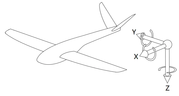
Appendix 3 Definition of Carrier’s Coordinate System
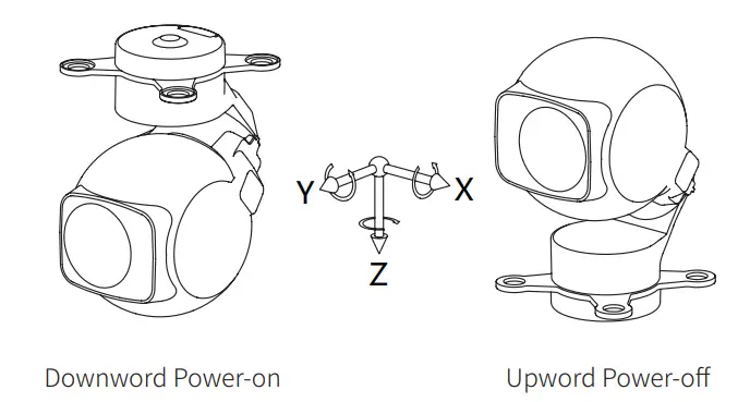
Appendix 4 Definition of Camera’s Coordinate System and Rotate Order
- Coordinate system definition
 The control port of the pod should point to negative X-ward of the carrier. The damping platform should be parallel to the XOY plane of the carrier. The pod should be mount as close as possible to the C.G. of the carrier.
 - Rotate order: Z → Y → X.
- Angles transformation:
- Define:
- CamPhi: Absolute roll angle of camera (Main data frame from GCU, byte 18~19)
- CamThe: Absolute pitch angle of camera (Main data frame from GCU, byte 20~21)
- CamPsi: Absolute yaw angle of camera (Main data frame from GCU, byte 22~23)
- AngleX: X-axis absolute angle of camera
- AngleY: Y-axis absolute angle of camera
- AngleZ: Z-axis absolute angle of camera
- The parameters above are transformed as below
- AngleZ += 90;
- WARP (AngleZ , 360);
- CamPhi = +AngleY;
- CamThe = -AngleX;
- CamPsi = +AngleZ;
- Define:
Appendix 5 Example Data Package
- Null command
A8 E5 48 00 02 00 00 00 00 00 00 00 00 00 00 00 00 00 00 00 00 00 00 00 00 00 00 00 00 00 01 00 00 00 00 00 00 00 00 00 00 00 00 00 00 00 00 00 00 00 00 00 00 00 00 00 00 00 00 00 00 00 00 00 00 00 00 00 00 00 FD 13 - Pitch control (keep current control mode, control value 100)
A8 E5 48 00 02 00 00 64 00 00 00 04 00 00 00 00 00 00 00 00 00 00 00 00 00 00 00 00 00 00 01 00 00 00 00 00 00 00 00 00 00 00 00 00 00 00 00 00 00 00 00 00 00 00 00 00 00 00 00 00 00 00 00 00 00 00 00 00 00 00 E7 9F - Pitch control (keep current control mode, control value -100)
A8 E5 48 00 02 00 00 9C FF 00 00 04 00 00 00 00 00 00 00 00 00 00 00 00 00 00 00 00 00 00 01 00 00 00 00 00 00 00 00 00 00 00 00 00 00 00 00 00 00 00 00 00 00 00 00 00 00 00 00 00 00 00 00 00 00 00 00 00 00 00 0F 0E - Yaw control (keep current control mode, control value 1000)
A8 E5 48 00 02 00 00 00 00 E8 03 04 00 00 00 00 00 00 00 00 00 00 00 00 00 00 00 00 00 00 01 00 00 00 00 00 00 00 00 00 00 00 00 00 00 00 00 00 00 00 00 00 00 00 00 00 00 00 00 00 00 00 00 00 00 00 00 00 00 00 DC 69 - Neutral
A8 E5 48 00 02 00 00 00 00 00 00 00 00 00 00 00 00 00 00 00 00 00 00 00 00 00 00 00 00 00 01 00 00 00 00 00 00 00 00 00 00 00 00 00 00 00 00 00 00 00 00 00 00 00 00 00 00 00 00 00 00 00 00 00 00 00 00 00 00 03 CD 70 - OSD displays carrier’s coordinate
A8 E5 49 00 02 00 00 00 00 00 00 00 00 00 00 00 00 00 00 00 00 00 00 00 00 00 00 00 00 00 01 00 00 00 00 00 00 00 00 00 00 00 00 00 00 00 00 00 00 00 00 00 00 00 00 00 00 00 00 00 00 00 00 00 00 00 00 00 00 06 00 E7 0D - OSD displays target’s coordinate
A8 E5 49 00 02 00 00 00 00 00 00 00 00 00 00 00 00 00 00 00 00 00 00 00 00 00 00 00 00 00 01 00 00 00 00 00 00 00 00 00 00 00 00 00 00 00 00 00 00 00 00 00 00 00 00 00 00 00 00 00 00 00 00 00 00 00 00 00 00 06 01 F7 2C - Image auto reverse on
A8 E5 49 00 02 00 00 00 00 00 00 00 00 00 00 00 00 00 00 00 00 00 00 00 00 00 00 00 00 00 01 00 00 00 00 00 00 00 00 00 00 00 00 00 00 00 00 00 00 00 00 00 00 00 00 00 00 00 00 00 00 00 00 00 00 00 00 00 00 07 00 D4 3C - Image auto reverse off
A8 E5 49 00 02 00 00 00 00 00 00 00 00 00 00 00 00 00 00 00 00 00 00 00 00 00 00 00 00 00 01 00 00 00 00 00 00 00 00 00 00 00 00 00 00 00 00 00 00 00 00 00 00 00 00 00 00 00 00 00 00 00 00 00 00 00 00 00 00 07 01 C4 1D - Time zone setting (UTC-2)
A8 E5 49 00 02 00 00 00 00 00 00 00 00 00 00 00 00 00 00 00 00 00 00 00 00 00 00 00 00 00 01 00 00 00 00 00 00 00 00 00 00 00 00 00 00 00 00 00 00 00 00 00 00 00 00 00 00 00 00 00 00 00 00 00 00 00 00 00 00 08 FE CA D3 - Angle control 1 (control values invalid)
A8 E5 48 00 02 00 00 00 00 00 00 00 00 00 00 00 00 00 00 00 00 00 00 00 00 00 00 00 00 00 00 00 00 00 00 00 00 00 00 00 00 00 00 00 00 00 00 00 00 00 00 00 00 00 00 00 00 00 00 00 00 00 00 00 00 00 00 00 00 10 01 86 - Angle control 1 (Euler angle: roll 0° , pitch 45° , yaw 60° )
A8 E5 48 00 02 00 00 94 11 70 17 04 00 00 00 00 00 00 00 00 00 00 00 00 00 00 00 00 00 00 00 00 00 00 00 00 00 00 00 00 00 00 00 00 00 00 00 00 00 00 00 00 00 00 00 00 00 00 00 00 00 00 00 00 00 00 00 00 00 10 4A 53 - Angle control 1 (Euler angle: roll 20° , pitch 0° , yaw 0° )
A8 E5 48 00 02 D0 07 00 00 00 00 04 00 00 00 00 00 00 00 00 00 00 00 00 00 00 00 00 00 00 00 00 00 00 00 00 00 00 00 00 00 00 00 00 00 00 00 00 00 00 00 00 00 00 00 00 00 00 00 00 00 00 00 00 00 00 00 00 00 10 05 F7 - Head lock (control values invalid)
A8 E5 48 00 02 00 00 00 00 00 00 00 00 00 00 00 00 00 00 00 00 00 00 00 00 00 00 00 00 00 01 00 00 00 00 00 00 00 00 00 00 00 00 00 00 00 00 - Head lock (relative angular velocity +10° /s)
A8 E5 48 00 02 00 00 00 00 E8 03 04 00 00 00 00 00 00 00 00 00 00 00 00 00 00 00 00 00 00 01 00 00 00 00 00 00 00 00 00 00 00 00 00 00 00 00 00 00 00 00 00 00 00 00 00 00 00 00 00 00 00 00 00 00 00 00 00 00 11 DE 79 - Head follow (control values invalid)
A8 E5 48 00 02 00 00 00 00 00 00 00 00 00 00 00 00 00 00 00 00 00 00 00 00 00 00 00 00 00 01 00 00 00 00 00 00 00 00 00 00 00 00 00 00 00 00 00 00 00 00 00 00 00 00 00 00 00 00 00 00 00 00 00 00 00 00 00 00 12 CF 60 - Orthoview (control values invalid)
A8 E5 48 00 02 00 00 00 00 00 00 00 00 00 00 00 00 00 00 00 00 00 00 00 00 00 00 00 00 00 01 00 00 00 00 00 00 00 00 00 00 00 00 00 00 00 00 00 00 00 00 00 00 00 00 00 00 00 00 00 00 00 00 00 00 00 00 00 00 13 DF 41 - Euler angle control (control values invalid)
A8 E5 48 00 02 00 00 00 00 00 00 00 00 00 00 00 00 00 00 00 00 00 00 00 00 00 00 00 00 00 00 00 00 00 00 00 00 00 00 00 00 00 00 00 00 00 00 00 00 00 00 00 00 00 00 00 00 00 00 00 00 00 00 00 00 00 00 00 00 14 41 02 - Euler angle control (Euler angle: roll 0° , pitch -45° , yaw 0° )
A8 E5 48 00 02 00 00 6C EE 00 00 04 00 00 00 00 00 00 00 00 00 00 00 00 00 00 00 00 00 00 00 00 00 00 00 00 00 00 00 00 00 00 00 00 00 00 00 00 00 00 00 00 00 00 00 00 00 00 00 00 00 00 00 00 00 00 00 00 00 14 A5 6A - Start tracking (X0=100, Y0=100, X1=105, Y1=105)
A8 E5 52 00 02 00 00 00 00 00 00 00 00 00 00 00 00 00 00 00 00 00 00 00 00 00 00 00 00 00 01 00 00 00 00 00 00 00 00 00 00 00 00 00 00 00 00 00 00 00 00 00 00 00 00 00 00 00 00 00 00 00 00 00 00 00 00 00 00 17 01 01 64 00 64 00 69 00 69 00 20 55 - Exit tracking
A8 E5 52 00 02 00 00 00 00 00 00 00 00 00 00 00 00 00 00 00 00 00 00 00 00 00 00 00 00 00 01 00 00 00 00 00 00 00 00 00 00 00 00 00 00 00 00 00 00 00 00 00 00 00 00 00 00 00 00 00 00 00 00 00 00 00 00 00 00 17 01 00 64 00 64 00 69 00 69 00 CB 76 - Click to aim (X=100, Y=100)
A8 E5 4D 00 02 00 00 00 00 00 00 00 00 00 00 00 00 00 00 00 00 00 00 00 00 00 00 00 00 00 01 00 00 00 00 00 00 00 00 00 00 00 00 00 00 00 00 00 00 00 00 00 00 00 00 00 00 00 00 00 00 00 00 00 00 00 00 00 00 1A 01 64 00 64 00 48 AF - Click to aim (X=5000, Y=5000)
A8 E5 4D 00 02 00 00 00 00 00 00 00 00 00 00 00 00 00 00 00 00 00 00 00 00 00 00 00 00 00 01 00 00 00 00 00 00 00 00 00 00 00 00 00 00 00 00 00 00 00 00 00 00 00 00 00 00 00 00 00 00 00 00 00 00 00 00 00 00 1A 01 88 13 88 13 EE C9 - Click to aim (X=10000, Y=10000)
A8 E5 4D 00 02 00 00 00 00 00 00 00 00 00 00 00 00 00 00 00 00 00 00 00 00 00 00 00 00 00 01 00 00 00 00 00 00 00 00 00 00 00 00 00 00 00 00 00 00 00 00 00 00 00 00 00 00 00 00 00 00 00 00 00 00 00 00 00 00 1A 01 10 27 10 27 53 65 - Click to aim (X=10000, Y=5000)
A8 E5 4D 00 02 00 00 00 00 00 00 00 00 00 00 00 00 00 00 00 00 00 00 00 00 00 00 00 00 00 01 00 00 00 00 00 00 00 00 00 00 00 00 00 00 00 00 00 00 00 00 00 00 00 00 00 00 00 00 00 00 00 00 00 00 00 00 00 00 1A 01 10 27 88 13 B4 F0 - External track (X=100, Y=20)
A8 E5 4E 00 02 00 00 00 00 00 00 00 00 00 00 00 00 00 00 00 00 00 00 00 00 00 00 00 00 00 01 00 00 00 00 00 00 00 00 00 00 00 00 00 00 00 00 00 00 00 00 00 00 00 00 00 00 00 00 00 00 00 00 00 00 00 00 00 00 1B 01 9C FF 14 00 02 53 0A - Angle control 2 (control values invalid)
A8 E5 48 00 02 00 00 00 00 00 00 00 00 00 00 00 00 00 00 00 00 00 00 00 00 00 00 00 00 00 01 00 00 00 00 00 00 00 00 00 00 00 00 00 00 00 00 00 00 00 00 00 00 00 00 00 00 00 00 00 00 00 00 00 00 00 00 00 00 1C 2E AE - Shutter
A8 E5 49 00 02 00 00 00 00 00 00 00 00 00 00 00 00 00 00 00 00 00 00 00 00 00 00 00 00 00 01 00 00 00 00 00 00 00 00 00 00 00 00 00 00 00 00 00 00 00 00 00 00 00 00 00 00 00 00 00 00 00 00 00 00 00 00 00 00 20 01 5B 6C - Start/stop recording
A8 E5 49 00 02 00 00 00 00 00 00 00 00 00 00 00 00 00 00 00 00 00 00 00 00 00 00 00 00 00 01 00 00 00 00 00 00 00 00 00 00 00 00 00 00 00 00 00 00 00 00 00 00 00 00 00 00 00 00 00 00 00 00 00 00 00 00 00 00 21 01 68 5D - Camera 1 continuously zooms in
A8 E5 49 00 02 00 00 00 00 00 00 00 00 00 00 00 00 00 00 00 00 00 00 00 00 00 00 00 00 00 01 00 00 00 00 00 00 00 00 00 00 00 00 00 00 00 00 00 00 00 00 00 00 00 00 00 00 00 00 00 00 00 00 00 00 00 00 00 00 22 01 3D 0E - Camera 1 continuously zooms out
A8 E5 49 00 02 00 00 00 00 00 00 00 00 00 00 00 00 00 00 00 00 00 00 00 00 00 00 00 00 00 01 00 00 00 00 00 00 00 00 00 00 00 00 00 00 00 00 00 00 00 00 00 00 00 00 00 00 00 00 00 00 00 00 00 00 00 00 00 00 23 01 0E 3F - Camera 1 stop zooming
A8 E5 49 00 02 00 00 00 00 00 00 00 00 00 00 00 00 00 00 00 00 00 00 00 00 00 00 00 00 00 01 00 00 00 00 00 00 00 00 00 00 00 00 00 00 00 00 00 00 00 00 00 00 00 00 00 00 00 00 00 00 00 00 00 00 00 00 00 00 24 01 97 A8 - Camera 1 zooms to specified rate (5000, corresponds to half of max rate)
A8 E5 4B 00 02 00 00 00 00 00 00 00 00 00 00 00 00 00 00 00 00 00 00 00 00 00 00 00 00 00 01 00 00 00 00 00 00 00 00 00 00 00 00 00 00 00 00 00 00 00 00 00 00 00 00 00 00 00 00 00 00 00 00 00 00 00 00 00 00 25 01 88 13 73 0C - All cameras zoom to specified rate (1.0x)
A8 E5 4B 00 02 00 00 00 00 00 00 00 00 00 00 00 00 00 00 00 00 00 00 00 00 00 00 00 00 00 00 00 00 00 00 00 00 00 00 00 00 00 00 00 00 00 00 00 00 00 00 00 00 00 00 00 00 00 00 00 00 00 00 00 00 00 00 00 00 25 FF F6 FF F6 21 - All cameras zoom to specified rate (5.5x)
A8 E5 4B 00 02 00 00 00 00 00 00 00 00 00 00 00 00 00 00 00 00 00 00 00 00 00 00 00 00 00 00 00 00 00 00 00 00 00 00 00 00 00 00 00 00 00 00 00 00 00 00 00 00 00 00 00 00 00 00 00 00 00 00 00 00 00 00 00 00 25 FF C9 FF E3 8A - Camera 1 zooms to specified rate (60.3x)
A8 E5 4B 00 02 00 00 00 00 00 00 00 00 00 00 00 00 00 00 00 00 00 00 00 00 00 00 00 00 00 00 00 00 00 00 00 00 00 00 00 00 00 00 00 00 00 00 00 00 00 00 00 00 00 00 00 00 00 00 00 00 00 00 00 00 00 00 00 00 25 01 A5 FD 75 DC - Focus
A8 E5 49 00 02 00 00 00 00 00 00 00 00 00 00 00 00 00 00 00 00 00 00 00 00 00 00 00 00 00 01 00 00 00 00 00 00 00 00 00 00 00 00 00 00 00 00 00 00 00 00 00 00 00 00 00 00 00 00 00 00 00 00 00 00 00 00 00 00 26 01 F1 CA - Next palette option
A8 E5 4A 00 02 00 00 00 00 00 00 00 00 00 00 00 00 00 00 00 00 00 00 00 00 00 00 00 00 00 01 00 00 00 00 00 00 00 00 00 00 00 00 00 00 00 00 00 00 00 00 00 00 00 00 00 00 00 00 00 00 00 00 00 00 00 00 00 00 2A 02 00 8B E6 - Palette mode 3
A8 E5 4A 00 02 00 00 00 00 00 00 00 00 00 00 00 00 00 00 00 00 00 00 00 00 00 00 00 00 00 01 00 00 00 00 00 00 00 00 00 00 00 00 00 00 00 00 00 00 00 00 00 00 00 00 00 00 00 00 00 00 00 00 00 00 00 00 00 00 2A 02 03 BB 85 - Night vision on
A8 E5 4A 00 02 00 00 00 00 00 00 00 00 00 00 00 00 00 00 00 00 00 00 00 00 00 00 00 00 00 01 00 00 00 00 00 00 00 00 00 00 00 00 00 00 00 00 00 00 00 00 00 00 00 00 00 00 00 00 00 00 00 00 00 00 00 00 00 00 2B 01 01 F9 A4 - Night vision off
A8 E5 4A 00 02 00 00 00 00 00 00 00 00 00 00 00 00 00 00 00 00 00 00 00 00 00 00 00 00 00 01 00 00 00 00 00 00 00 00 00 00 00 00 00 00 00 00 00 00 00 00 00 00 00 00 00 00 00 00 00 00 00 00 00 00 00 00 00 00 2B 01 00 E9 85 - Area temperature measurement on (X0=4000, Y0=4000, X1=6000, Y1=6000)
A8 E5 52 00 02 00 00 00 00 00 00 01 00 00 00 00 00 00 00 00 00 00 00 00 00 00 00 00 00 00 01 00 00 00 00 00 00 01 00 00 00 00 00 00 00 00 00 00 00 00 00 00 00 00 00 00 00 00 00 00 00 00 00 00 00 00 00 00 30 02 01 A0 0F A0 0F 70 17 70 17 BE 6D - Area temperature measurement off
A8 E5 52 00 02 00 00 00 00 00 00 01 00 00 00 00 00 00 00 00 00 00 00 00 00 00 00 00 00 00 01 00 00 00 00 00 00 01 00 00 00 00 00 00 00 00 00 00 00 00 00 00 00 00 00 00 00 00 00 00 00 00 00 00 00 00 00 00 00 30 02 00 00 00 00 00 00 00 00 00 33 96 - Temperature alert on (high alert temperature 30.2 ° C, low alert temperature 20.0° C)
A8 E5 4E 00 02 00 00 00 00 00 00 00 00 00 00 00 00 00 00 00 00 00 00 00 00 00 00 00 00 00 01 00 00 00 00 00 00 01 00 00 00 00 00 00 00 00 00 00 00 00 00 00 00 00 00 00 00 00 00 00 00 00 00 00 00 00 00 00 00 31 02 01 2E 01 C8 00 E8 93 - Temperature alert off
A8 E5 4E 00 02 00 00 00 00 00 00 00 00 00 00 00 00 00 00 00 00 00 00 00 00 00 00 00 00 00 01 00 00 00 00 00 00 01 00 00 00 00 00 00 00 00 00 00 00 00 00 00 00 00 00 00 00 00 00 00 00 00 00 00 00 00 00 00 00 31 02 00 2E 01 C8 00 42 C2 - Isotherm on (interval mode, 15.0° C~25.2° C)
A8 E5 4E 00 02 00 00 00 00 00 00 00 00 00 00 00 00 00 00 00 00 00 00 00 00 00 00 00 00 00 01 00 00 00 00 00 00 01 00 00 00 00 00 00 00 00 00 00 00 00 00 00 00 00 00 00 00 00 00 00 00 00 00 00 00 00 00 00 00 32 02 01 FC 00 96 00 6F FA - Isotherm off
A8 E5 4E 00 02 00 00 00 00 00 00 00 00 00 00 00 00 00 00 00 00 00 00 00 00 00 00 00 00 00 01 00 00 00 00 00 00 01 00 00 00 00 00 00 00 00 00 00 00 00 00 00 00 00 00 00 00 00 00 00 00 00 00 00 00 00 00 00 00 32 02 00 FC 00 96 00 C5 AB - Spot temperature measurement on (X=4000, Y=5000)
A8 E5 4E 00 02 00 00 00 00 00 00 00 00 00 00 00 00 00 00 00 00 00 00 00 00 00 00 00 00 00 01 00 00 00 00 00 00 01 00 00 00 00 00 00 00 00 00 00 00 00 00 00 00 00 00 00 00 00 00 00 00 00 00 00 00 00 00 00 00 33 02 01 A0 0F 88 13 C3 8D - Spot temperature measurement off
A8 E5 4E 00 02 00 00 00 00 00 00 00 00 00 00 00 00 00 00 00 00 00 00 00 00 00 00 00 00 00 01 00 00 00 00 00 00 01 00 00 00 00 00 00 00 00 00 00 00 00 00 00 00 00 00 00 00 00 00 00 00 00 00 00 00 00 00 00 00 33 02 00 00 00 88 13 AF 9B - OSD on
A8 E5 49 00 02 00 00 00 00 00 00 00 00 00 00 00 00 00 00 00 00 00 00 00 00 00 00 00 00 00 00 00 00 00 00 00 00 00 00 00 00 00 00 00 00 00 00 00 00 00 00 00 00 00 00 00 00 00 00 00 00 00 00 00 00 00 00 00 00 73 01 B8 60 - OSD off
A8 E5 49 00 02 00 00 00 00 00 00 00 00 00 00 00 00 00 00 00 00 00 00 00 00 00 00 00 00 00 00 00 00 00 00 00 00 00 00 00 00 00 00 00 00 00 00 00 00 00 00 00 00 00 00 00 00 00 00 00 00 00 00 00 00 00 00 00 00 73 00 A8 41 - Next pic-in-pic option
A8 E5 49 00 02 00 00 00 00 00 00 00 00 00 00 00 00 00 00 00 00 00 00 00 00 00 00 00 00 00 01 00 00 00 00 00 00 00 00 00 00 00 00 00 00 00 00 00 00 00 00 00 00 00 00 00 00 00 00 00 00 00 00 00 00 00 00 00 00 74 00 89 36 - Pic-in-pic mode 3
A8 E5 49 00 02 00 00 00 00 00 00 00 00 00 00 00 00 00 00 00 00 00 00 00 00 00 00 00 00 00 01 00 00 00 00 00 00 00 00 00 00 00 00 00 00 00 00 00 00 00 00 00 00 00 00 00 00 00 00 00 00 00 00 00 00 00 00 00 00 74 03 B9 55 - Target detection on
A8 E5 49 00 02 00 00 00 00 00 00 00 00 00 00 00 00 00 00 00 00 00 00 00 00 00 00 00 00 00 01 00 00 00 00 00 00 00 00 00 00 00 00 00 00 00 00 00 00 00 00 00 00 00 00 00 00 00 00 00 00 00 00 00 00 00 00 00 00 75 01 AA 26 - Target detection off
A8 E5 49 00 02 00 00 00 00 00 00 00 00 00 00 00 00 00 00 00 00 00 00 00 00 00 00 00 00 00 01 00 00 00 00 00 00 00 00 00 00 00 00 00 00 00 00 00 00 00 00 00 00 00 00 00 00 00 00 00 00 00 00 00 00 00 00 00 00 75 00 BA 07 - Zoom camera digital zoom on
A8 E5 49 00 02 00 00 00 00 00 00 00 00 00 00 00 00 00 00 00 00 00 00 00 00 00 00 00 00 00 01 00 00 00 00 00 00 00 00 00 00 00 00 00 00 00 00 00 00 00 00 00 00 00 00 00 00 00 00 00 00 00 00 00 00 00 00 00 00 76 01 FF 75 - Zoom camera digital zoom off
A8 E5 49 00 02 00 00 00 00 00 00 00 00 00 00 00 00 00 00 00 00 00 00 00 00 00 00 00 00 00 01 00 00 00 00 00 00 00 00 00 00 00 00 00 00 00 00 00 00 00 00 00 00 00 00 00 00 00 00 00 00 00 00 00 00 00 00 00 00 76 - 00 EF 54
- Lighting on (255)
A8 E5 49 00 02 00 00 00 00 00 00 00 00 00 00 00 00 00 00 00 00 00 00 00 00 00 00 00 00 00 01 00 00 00 00 00 00 00 00 00 00 00 00 00 00 00 00 00 00 00 00 00 00 00 00 00 00 00 00 00 00 00 00 00 00 00 00 00 00 80 FF 48 C3 - Lighting off
A8 E5 49 00 02 00 00 00 00 00 00 00 00 00 00 00 00 00 00 00 00 00 00 00 00 00 00 00 00 00 01 00 00 00 00 00 00 00 00 00 00 00 00 00 00 00 00 00 00 00 00 00 00 00 00 00 00 00 00 00 00 00 00 00 00 00 00 00 00 80 00 56 33 - Continuously ranging on
A8 E5 49 00 02 00 00 00 00 00 00 00 00 00 00 00 00 00 00 00 00 00 00 00 00 00 00 00 00 00 01 00 00 00 00 00 00 00 00 00 00 00 00 00 00 00 00 00 00 00 00 00 00 00 00 00 00 00 00 00 00 00 00 00 00 00 00 00 00 81 02 45 40 - Continuously ranging off
A8 E5 49 00 02 00 00 00 00 00 00 00 00 00 00 00 00 00 00 00 00 00 00 00 00 00 00 00 00 00 01 00 00 00 00 00 00 00 00 00 00 00 00 00 00 00 00 00 00 00 00 00 00 00 00 00 00 00 00 00 00 00 00 00 00 00 00 00 00 81 00 65 02
Appendix 6 GPS time & UTC conversion function (without leap second processing)
static const uint16_t gpst0[] = {1980, 1, 6, 0, 0, 0}; uint64_t epoch2time(const uint16_t *ep) { const uint16_t _day[] = {1, 32, 60, 91, 121, 152, 182, 213, 244, 274, 305, 335}; uint64_t seconds = 0; uint16_t days, year = ep[0], mon = ep[1], day = ep[2]; if (year < 1970 || 2099 < year || mon < 1 || 12 < mon) return seconds; /* leap year if year%4==0 in 1901-2099 */ days=(year-1970)*365+(year-1969)/4+_day[mon-1]+day-2+(year%4==0 && mon>=3?1:0); seconds = floor(ep[5]);seconds = (uint64_t)days * 86400 + ep[3] * 3600 + ep[4] * 60 + seconds; return seconds; } uint64_t gpst2time(int16_t week, uint32_t sec){ uint64_t t = epoch2time(gpst0); if (sec < -1E9 || 1E9 < sec) sec = 0.0; t += 86400 * 7 * week + sec; return t; } uint8_t time2gps(uint64_t time, int16_t *week, uint32_t *msec){ uint64_t t = epoch2time(gpst0); t = time – t; * week = t / 604800; // 604800=7*86400 * msec = (t % 604800) * 1000; return 1; }
Appendix 7 Pod Code
| Code | Model |
|---|---|
| 0 | Z-6A |
| 2 | Z-6C |
| 3 | M-2400G2 |
| 21 | Z-8TA |
| 22 | Z-8TB |
| 24 | Z-8RA |
| 25 | Z-8RB |
| 26 | Z-8RC |
| 27 | Z-8LA |
| 30 | Z-9A |
| 31 | Z-9B |
| 40 | D-80AI |
| 41 | D-90AI |
| 44 | D-80Pro |
| 45 | D-90Pro |
| 49 | Z-1PRO |
| 50 | Z-1MINI |
| 51 | Z-2PRO |
| 52 | Z-2MINI |
| 53 | D-125AI |
| 54 | D-150AI |
| 55 | D-90DE |
| 56 | D-115AI |
NANJING XIANFEI ROBOT TECHNOLOGY CO., LTD.
FAQ
Q: What is the purpose of the private protocol used by the GCU?
A: The private protocol ensures secure and efficient communication between the GCU and connected devices.
Q: How can I update the protocol version of the GCU?
A: To update the protocol version, refer to the product manual for specific instructions provided by the manufacturer.
Documents / Resources
 |
Robot XF(A5) V2.0.5 GCU Private Protocol [pdf] User Guide XF A5 V2.0.5, XF A5 V2.0.1, XF A5 V2.0.2, XF A5 V2.0.5 GCU Private Protocol, XF A5 V2.0.5, GCU Private Protocol, Private Protocol, Protocol |