![]()
![]()
![]()

FTI-CDP1: Vehicle Coverage and Preparation Notes
| Make | Model | Year | Install | CAN | Lights | IGN | Hood | I/O Changes |
| DL-CH7 | Park / Auto | Green White/Blue | ||||||
| Dodge | Dairage PTS | 2013-16 | Type 2 | CJB | Type A | BCM | BCM |
Firmware: Covered vehicles use either BLADE-AL(DL)-CH7, confirm application, flash module, and update the controllerfirmware before installing.
CAN:
Type 1 vehicles use CAN connections on the harness in OBD-II, the included CAN extension is not necessary for this type of installation.
Lights:
Type A parking lights use the 6-pin connector, make sure the unused 10-pin connector is properly secured for safety.
Ignition:
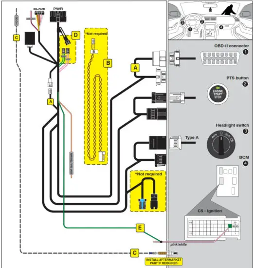
Common ignition provisions are listed on the BLADE diagram, ignition is also available at the vehicle BCM (C5/E connector, pink/white, pin #27). The hood status wire is available at the vehicle BCM, C1 connector, pin #11 (violet/blue).
FTI-CDP1 – Installation and Configuration Notes
B. CAN Type 2 extension cable is not used on covered vehicles, ensure all unused connections are properly insulated and secured for safety.
E. Ignition connection varies by vehicle, component locator illustrates common connection to BCM connector C5 (pin #27, pink/white), see notes on coverage page for location details and exceptions
 FEATURE COVERAGE
| IMMOBILIZER DATA | |
| PRIORITY UNLOCK | |
| DOOR LOCK | |
| DOOR UNLOCK | |
| ARM OEM ALARM | |
| DISARM OEM ALARM | |
| DOOR STATUS | |
| RAP SHUTDOWN | |
| BRAKE STATUS | |
| E-BRAKE STATUS | |
| TACH OUTPUT | |
| SECURE TAKEOVER | |
| PARKING LIGHTS |
- FT-DAS Required for manual transmission.
- BOTH Red & Red/White MUST be connected with high current application.
 CM900AS/900S Jumper
 FTI-CDP1 – DL-CH7 – Type 1
2013-16 Dodge Dart PTS
LED Programming Error Codes
Module LED flashes RED during programming
- 1x – CAN error, check CAN wiring and voltages
- 2x – Key code not learned, confirm unlock sent, check CAN
- 3x – No PTS signal, check button connection
- 4x – No immobilizer data, check wiring
- 4x – No immobilizer, confirm only one key in vehicle
- 5x – No ignition, check wiring
- 6x – VIN error, check CAN wiring
- 7x – PTS signal error, check button connection
- 8x – No PTS signal, check button connection
INSTALL GUIDE
COM-BLADE-AL(DL)-CH7-EN
20201117
CARTRIDGE INSTALLATION
- Slide cartridge into unit. Notice button under LED.

- Ready for Module Programming Procedure.
MODULE PROGRAMMING PROCEDURE – WITH KLON – 1 OF 2
- Close driver door
 Re-open driver door to wake up data bus
 - Press UNLOCKon keyfob 1.

- Wait, LED will flash BLUE once [1x].

- Remove valet key from keyfob 1.

- Remove batteries from keyfob 1.

- Push start button twice [2x] with keyfob 1 to ON position (No battery)

- Wait, LED will turn solid RED.

- Push start button once [1x] to OFF position.

- Push start button twice [2x] with keyfob 1 to ON position (No battery)

- Wait, LED flashes BLUE rapidly, proceed to step 11. If LED tums solid RED repeat steps 8 to 10.

- Push start button once [1x] to OFF position.

- Disconnect all connectors from remote starter except the power connector.

- Disconnect the power connector.
 MODULE PROGRAMMING PROCEDURE – WITH KLON – 2 OF 2
 - Remove remote starter from vehicle.

- Connect remote starter to computer.

- Proceed with extended programming.

- Connect remote starter to vehicle.

- Close driver door.
 Re-open driver door to wake up data bus.
 - Push start button twice [2x] with keyfob 1 to ON position. (No battery)

- Wait, LED will turn solid BLUE for 2 seconds.

- Push start button once [1x] to OFF position.
 Module Programming
Procedure completed - Insert battery in keyfob 1.

WARNING: READ BEFORE REMOTE STARTING THE VEHICLE
IMPORTANT
- All OEM keyfobs must be at least 10 feet away from the vehicle. All vehicle doors must be closed and locked prior to remote start sequence. Failure to comply will result in remote starter malfunction.
TAKE OVER PROCEDURE – TO THE VEHICLE OWNER
NOTE
- All vehicle doors must be closed and locked prior to remote start sequence.

- Press UNLOCK on after-market remote.

- TIME RESTRICTION
With in 45 SECONDS from previous step. Open vehicle door.
Enter vehicle.
Close vehicle door.
Press and release BRAKE pedal. - Take over procedure completed.
 Failure to follow procedure within time restriction will result in vehicle engine shutdown.
![]() WWW.IDATALINK.COM
WWW.IDATALINK.COM
Automotive Data Solutions Inc. © 2020
Documents / Resources
 |
idatalink FTI-CDP1-CH7 LED Programming Error Codes Module [pdf] Installation Guide FTI-CDP1-CH7, CM7000-7200, CM900AS-900S, FTI-CDP1-CH7 LED Programming Error Codes Module, FTI-CDP1-CH7, LED Programming Error Codes Module, Programming Error Codes Module, Error Codes Module, Codes Module, Module |
 |
idatalink FTI-CDP1-CH7 LED Programming Error Codes Module [pdf] Installation Guide FTI-CDP1-CH7 LED Programming Error Codes Module, FTI-CDP1-CH7, LED Programming Error Codes Module, Programming Error Codes Module, Error Codes Module, Codes Module, Module |