iS7 DeviceNet Option Board
“
Specifications
- Device: SV – iS7 DeviceNet Option Board
- Power Supply: Supplied from inverter power
source - Input Voltage: 11 ~ 25V DC
- Current Consumption: Max. 60mA
- Network Topology: Free, Bus Topology
- Communication Baud Rate: 125kbps, 250kbps,
500kbps - Maximum Number of Nodes: 64 nodes (including
Master), Max. 64 stations per each segment
Product Usage Instructions
Safety Precautions
Before using the iS7 DeviceNet Option Board, please read and
follow the safety precautions listed below:
- WARNING: Do not remove the cover while power
is applied or the unit is in operation to prevent electric
shock. - CAUTION: Be cautious when handling CMOS
elements on the option board to avoid static electricity
failure.
Installation and Setup
Follow these steps to install and set up the iS7 DeviceNet
Option Board:
- Ensure the inverter power source is within the input voltage
range of 11 ~ 25V DC. - Connect the inverter body to the option board connector
accurately and securely. - Select the appropriate communication baud rate based on your
network requirements.
Configuration and Parameter Setting
To configure and set parameters for the DeviceNet communication
card, follow these guidelines:
- Check the parameter unit when setting parameters to avoid
communication errors. - Ensure proper termination and network topology setup for
effective communication.
Frequently Asked Questions (FAQ)
Q: Can I run the inverter with the front cover removed?
A: No, running the inverter with the front
cover removed may result in electric shock due to high voltage
terminals exposure. Always keep the cover on during operation.
Q: What should I do if I encounter a communication error?
A: If you encounter a communication error, make
sure to check the connection between the inverter body and the
option board. Ensure they are accurately coincided and securely
connected.
“`
Safety Precaution
SV – iS7 DeviceNet Manual
First thank you for using our iS7 DeviceNet Option Board!
Please follow the following safety attentions since they are intended to prevent any possible accident and danger so that you can use this product safely and correctly.
Safety attentions may classify into `Warning’ and `Caution’ and their meaning is as following:
Symbol
Meaning
WARNING
This symbol indicates the possibility of death or serious injury.
CAUTION
This symbol indicates the possibility of injury or damage to property.
The meaning of each symbol in this manual and on your equipment is as follows.
Symbol
Meaning
This is the safety alert symbol. Read and follow instructions carefully to avoid dangerous situation.
This symbol alerts the user to the presence of
“dangerous voltage” inside the product that might cause harm or electric shock.
After reading this manual, keep it in the place that the user always can contact. This manual should be given to the person who actually uses the products and is responsible for their maintenance.
WARNING
Do not remove the cover while power is applied or the unit is in operation. Otherwise, electric shock could occur.
Do not run the inverter with the front cover removed. Otherwise, you may get an electric shock due to high voltage terminals or charged capacitor exposure.
Do not remove the cover except for periodic inspections or wiring, even if the input power is not applied.
1
I/O POINT MAP WARNING
Otherwise, you may access the charged circuits and get an electric shock. Wiring and periodic inspections should be performed at least 10
minutes after disconnecting the input power and after checking the DC link voltage is discharged with a meter (below DC 30V). Otherwise, you may get an electric shock. Operate the switches with dry hands. Otherwise, you may get an electric shock. Do not use the cable when its insulating tube is damaged. Otherwise, you may get an electric shock. Do not subject the cables to scratches, excessive stress, heavy loads or pinching. Otherwise, you may get an electric shock.
CAUTION Be cautious when handling CMOS elements on the option board.
It may cause a failure due to static electricity. When changing and connecting communication signal lines,
proceed the work while the inverter is turned off. It may cause a communication error or failure. Make sure to connect the inverter body to the option board connector accurately coincided each other. It may cause a communication error or failure. Make sure to check the parameter unit when setting parameters. It may cause a communication error.
2
SV – iS7 DeviceNet Manual
Table of Contests
1. Introduction ………………………………………………………………………………………………………………. 4 2. DeviceNet communication card specification ………………………………………………………………… 4 3. Communication Cable Specifications …………………………………………………………………………… 5 4. Installation ……………………………………………………………………………………………………………….. 6 5. LED…………………………………………………………………………………………………………………………. 8 6. EDS (Electronic Data Sheets) …………………………………………………………………………………… 12 7. Keypad Parameter associated with DeviceNet …………………………………………………………….. 13 8. Definition of Object Map …………………………………………………………………………………………… 18
8. 1 Class 0x01 (Identity Object) Instance 1 (Entire device, host and adapter) ……………….. 19 8. 2 Class 0x03 (DeviceNet Object) Instance 1 ………………………………………………………….. 20 8. 3 Class 0x04 (Assembly Object)…………………………………………………………………………… 21 8.4 Class 0x05 (DeviceNet Connection Object)………………………………………………………….. 28 8.5 Class 0x28 (Motor Data Object) Instance 1 ………………………………………………………….. 29 8.6 Class 0x29 (Control Supervisor Object) Instance 1 ……………………………………………….. 30 8.7 Class 0x2A (AC Drive Object) Instance 1 …………………………………………………………….. 33 8.8 Class 0x64 (Inverter Object) Manufacture Profile ……………………………………………….. 34
3
I/O POINT MAP
1. Introduction
SV-iS7 DeviceNet communication card connect the SV-iS7 inverter with DeviceNet network. DeviceNet communication card enables the control and monitoring of inverter to be controlled by sequence program of PLC or Master module selected optionally. As one or more inverters are connected and operated with a communication line, it can reduce the installation cost compared with when communication is not used. Furthermore, simple wiring enables to the reduction of installation period and easy maintenance as well. A variety of peripheral devices such as PLC, etc. can be used to control the inverter, and factory automation is made easy by its advantage of the fact that it can be operated linked with a variety of systems such as PC, etc.
2. DeviceNet communication card specification
Terminology
Description
DeviceNet
Power Supply
communication Supplied from inverter power source Exterior power Input Voltage : 11 ~25V DC
source
Current consumption: Max. 60mA
Network topology
Free, Bus Topology
Communication Baud rate 125kbps, 250kbps, 500kbps
64 nodes (including Master), Max. 64 stations per each segment
Max. number of node
In the event of a Master node is connected to network, max.
number of the nodes connected is 63 nodes (64-1).
Device type
AC Drive
Explicit Peer to Peer Messaging
Kind
of
support Faulted Node Recovery(Off-Line)
communication
Master/Scanner (Predefined M/S Connection)
Polling
Terminating resistor
120 ohm 1/4W Lead Type
4
3. Communication Cable Specifications
R
Terminating resistor
Trunk Cable
SV – iS7 DeviceNet Manual
R
Drop Cable
For DeviceNet communication, DeviceNet standard cable specified by ODVA should be used. There are Thick or Thin type cable as DeviceNet standard cable. For DeviceNet standard cable, refer to ODVA homepage (http://www.odva.org).
Either Thick or Thin cable can be used for Trunk cable, but please use Thick cable in general. In case of Drop cable, use Thin cable is strongly recommended.
Maximum length of cable as below is the performance when DeviceNet standard cable was used.
Baud Rate 125 kbps 250 kbps 500 kbps
Trunk Cable length Thick Cable Thin Cable 500 m (1640 ft.) 250 m (820 ft.) 100 m (328 ft.) 100 m (328 ft.)
Drop Length (Thin Cable)
Max. length
Total sum
156 m (512 ft.)
6 m (20 ft.)
78 m (256 ft.)
39m (128ft.)
5
I/O POINT MAP
4. Installation
When unpacking DeviceNet communication card box, the contents consist of SV-iS7 communication card 1ea, Pluggable 5-pin connector 1ea, Lead type terminal resistor 120 (1/4W) 1ea, bolt that fastens SV-iS7 DeviceNet communication card to SV-iS7 inverter, and this manual for SV-iS7 DeviceNet.
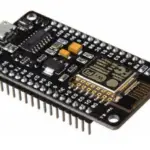
Layout of DeviceNet communication card is as below.
Zoom-in the connector
Installation figure is as below.
MS
LED
Not
NS
Not
using
LED
using
6
SV – iS7 DeviceNet Manual Instruction for installation) Don’t install or remove DeviceNet communication card with the power of inverter on. It may cause damages to both DeviceNet communication card and inverter. Be sure to install or remove communication card after the current of inverter’s condenser has been completely discharged. Don’t change the connection of communication signal line with the power of inverter on. Be sure to connect the inverter body and the option board connector exactly corresponded with each other. In the event of connecting of communication power source (24P, 24G), be sure to check they are V-(24G), V+(24P) silk of DeviceNet communication card before connecting them. When wiring is not connected correctly, it may cause the malfunction of communication. When configuring the Network, be sure to connect the terminal resistor to the device that is connected with the end part. Terminal resistor should be connected between CAN_L and CAN_H. The value of terminal resistor is 120 1/4W.
7
I/O POINT MAP
5. LED
DeviceNet communication card enclose 2 LEDs mounted; MS (Module status) LED and NS
(Network status) LED. Fundamental function of two LEDs is as below.
It is used to check whether the power source state of DeviceNet
MS LED (Module Status)
communication card is stable; whether CPU of DeviceNet communication card is regularly operating; whether the interface communication between DeviceNet communication card and inverter body is made in smooth manner. All the operations as above are normally made, MS LED will be lit in Solid
green.
NS LED
It is used to indicate the connection of DeviceNet communication card to
(Network communication on the network or the network power source status.
Status)
NS LED Status
LED
Status
Cause
Trouble shooting
5V power source is not Check whether the inverter power
supplied to DeviceNet source is supplied or 5V power
communication card. source is supplied to DeviceNet
Off-Line Off
(No Power)
communication card Checking of duplicated Wait for 5 seconds at LED Off status
Mac ID
while checking duplicated MAC ID
after initializing of Option board at
power On.
Communication
Normal operation prior to
environment is ready connecting.
Flashing On-Line
after checking
Green Not Connected
duplicated nodes but
any node is not
connected.
Solid Green
On-Line, Connected (Link OK)
Available to connect I/O Connection of one
communication (Poll) EMC or more is set up
Flashing Red
Connection TimeOut Critical Link Failure.
Time out occurred during Poll I/O communication
Inverter Reset Request the reset service to Identity Object and then re-connect I/O.
8
SV – iS7 DeviceNet Manual
LED
Status
Solid Red Abnormal condition
Green Self-diagnosis
Flashing Red
Red Communication Flashing Fault Green
Cause Duplicated MAC ID on Network Bus Off from Network configuration Network power source is not supplied from DeviceNet connector. Device under selfdiagnosis
In the event of Identity Communication Request Message is received at communication Fault status cased by failure of Network Access Passing.
Trouble shooting Change MAC ID set up.
Check the connection with signal cable and then do Comm Update. Check network cable and power supply.
Wait for a moment
Normal response
9
I/O POINT MAP
MS LED status
LED
Status
Off No Power
Solid Operational
Green
Solid Unrecoverable Red Fault
Green Self Test
Flashing Red
Cause DeviceNet communication card has no 5V power source.
Trouble shooting Checking whether inverter power On or not. Checking the power source of DeviceNet communication card (5V).
Normal operation
–
Interface communication between DeviceNet communication card and inverter is not made up.
Checking connection status between communication card and inverter.
DeviceNet
communication doing
–
self-testing.
LED Tip In the event that Reset occurs; MS (Module Status) LED flashes in Green Red at every 0.5 second at the beginning and the interface communication between DeviceNet communication card and inverter comes to normal state, it becomes solid Green. Then, NS (Network Status) LED flashes in Green Red at every 0.5 second. In the event there is no abnormality as a result of checking the redundant MAC ID, Network Status LED flashes in Green. It means this Device communication card is connected to the network in normal way, but communication is not made with any device. If it fails to run as above, please check any of following three cases. If it runs in normal way, you may disregard the following cases. If the interface communication between DeviceNet communication card and inverter doesn’t in normal way, MS (Module Status) LED becomes solid Red. Be sure to check the connection between inverter and DeviceNet communication card first, and then turn on the inverter.
10
SV – iS7 DeviceNet Manual In the event there is abnormality as a result of checking the redundant MAC ID, Network
Status LED becomes solid Red. In this case, please configure MAC ID at the other value using keypad. In the event that the option board is in communication with the other Device, NS (Network Status) LED becomes solid Green. In the event of EMC (Explicit Message Connection) by EMC Scanner (Master) Network Status LED becomes solid Green. If EMC setting is released here, it flashed in Green again after 10 seconds. Once EMC is achieved, I/O connection is available. In this case Network Status LED is still continued. In the event that no communication is made within the time I/O connection is set, Time Out occurs, Network Status LED flashed in Red. (This Status can be changed into flashing Green again depending on the time setting of EMC) In the event that EMC is connected but I/O connection is not connected, if wire came out, Green LED is still continued On status.
11
I/O POINT MAP
6. EDS (Electronic Data Sheets)
This file includes the information on the parameter of inverter. It is used when the user intends to control the parameters of SV-iS7 through the DeviceNet Manager program. In this case, it is necessary to install on PC the SV-iS7-use EDS file that we provide. EDS file can be downloaded from LS ELECTRIC website (http://www.lselectric.co.kr).
The name of EDS file: Lsis_iS7_AcDrive.EDS Revision: 2.01 The name of ICON: LSISInvDnet.ico Paste the file of Lsis_iS7_AcDrive.EDS on EDS file folder by Master Configuration program and ICON files save at ICON folder. Example) In case of SyCon program for XGT PLC series Paste the file of Lsis_iS7_AcDrive.EDS in DevNet folder and ICON files save in BMP folder. .
12
SV – iS7 DeviceNet Manual
7. Keypad Parameter associated with DeviceNet
Code
Name of Initial Value
Parameter
Range
CNF-30 Option-1 Type
–
–
DRV-6 DRV-7
Cmd Source Freq Ref Src
0. Keypad 1. Fx/Rx-1 2. Fx/Rx-2 1. Fx/Rx-1 3. Int 485 4. FieldBus 5. PLC 0. Keypad-1 1. Keypad-2 2. V1 3. I1 4. V2 0. Keypad-1 5. I2 6. Int 485 7. Encoder 8. FieldBus 9. PLC
COM-6 FBus S/W Ver
–
–
COM-7 FBus ID
COM-8
FBus BaudRate
COM-9 FBus Led
1 6. 125kbps
–
0~63 6. 125kbps 7 250kbps 8. 500kbps
–
Description When SV-iS7 DeviceNet communication card is installed, it indicates `DeviceNet’. To command inverter run with DeviceNet, it requires setting as 4. FieldBus.
To command Inverter frequency with DeviceNet, it requires setting as 8. FieldBus.
Indicates the version of DeviceNet communication card Requires setting at Baud Rate used in the network with which inverter is connected. –
13
I/O POINT MAP
Code
COM-29 COM-30
Name of Parameter
In Instance
ParaStatus Num
Initial Value Range
0. 70
0. 70 1. 71 2. 110 3. 111 4. 141 5. 142 6. 143 7. 144
–
–
COM-31 COM-32 COM-33 COM-34
Para Status-1 Para Status-2 Para Status-3 Para Status-4
COM-49 Out Instance
COM-50 Para Ctrl Num
–
0. 20
0~0xFFFF 0~0xFFFF 0~0xFFFF 0~0xFFFF 0. 20 1. 21 2. 100 3. 101 4. 121 5. 122 6. 123 7. 124
–
–
COM-51 Para Control-1 COM-52 Para Control-2 COM-53 Para Control-3 COM-54 Para Control-4 COM-94 Comm Update
14
–
0. No
0~0xFFFF 0~0xFFFF 0~0xFFFF 0~0xFFFF 0. No
1. Yes
Description
Set the value of input instance to be used in class 0x04 (Assembly Object). At this parameter value is set, the Data Type to be received (Master based) at the time of Poll I/O communication is decided. At the time of changing in Instance, DeviceNet communication card is automatically reset. It cannot be modified while the inverter runs.
When COM-29 In Instance is set at 141~144, the value of COM-30 ParaStauts Num is displayed automatically. This parameter value is changed depending on the value of COM29. It can be set/display in case of In Instance value between 141 ~ 144.
It set the value of Output Instance using at Class 0x04(Assembly Object). By setting of parameter value, Data type to transmit (Master-based) is decided in Poll I/O communication. In the event of changing Out Instance, DeviceNet communication card reset automatically. The parameter cannot be modified during run status.
When COM-49 Out Instance is set at 121~124, the value of COM-50 ParaStauts Ctrl Num is displayed automatically. This parameter value is changed depending on the value of COM-49. In event of the value of Out Instance between 121~124, it is displayed on Keypad and it can be set.
It is used when DeviceNet communication card is initialized. If COM-94 is set with Yes, it is initialized and then it indicates No automatically.
SV – iS7 DeviceNet Manual
Code
PRT-12
PRT-13 PRT-14
Name of Parameter
Lost Cmd Mode
Lost Cmd Time Lost Preset F
Initial Value Range
Description
0. None 1.0 sec 0.00 Hz
0. None
In case of DeviceNet communication, it
1. Free-Run
executes Lost Command of Communication
2. Dec
when Command of Polling Communication
3. Hold Input Data is lost.
4. Hold Output
5. Lost Preset
0.1~120.0 sec After I/O connection is disconnected, Lost
Command will be occurred after setting time.
Start Freq~ If run method (PRT-12 Lost Cmd Mode) is set
Max Freq
with No.5 Lost Preset when Speed Command
is lost, protective function is operated and it is
set the frequency to run continuously.
If you want to command for Run, Inverter Frequency by DeviceNet, DRV-06 Cmd Source, DRV-07 Freq Ref Src are set to FieldBus.
(1) FBus ID (COM-7) FBus ID falls under MAC ID (Media Access Control Identifier) that is called in DeviceNet. As this value is an indigenous value by which each Device is discriminated in DeviceNet network, it is not allowed for different Devices to have same values. This value is preset as 1 at the factory. In that event that interface communication is in trouble between DeviceNet communication card and inverter, change the MAC ID. In the event of modifying MAC ID during operation, DeviceNet communication card will be automatically reset. This is because it is essential to check if Device Using MAC ID value newly set is on the network. In the event the preset MAC ID value is the one that has already been used by other Device, NS (Network Status) LED will be changed to solid Red. Here, MAC ID can be changed into the other value using keypad again. After that, NS is flashing in green, it means its normal operation.
15
I/O POINT MAP
(2) FBus BaudRate (COM-8) In the event that the communication speed setting is not same as that used in the network, NS LED maintains Off state. In the event changing the Baud rate using keypad, in order for the changed Baud rate to influence the actual communication speed, it is necessary to send Reset service to the Identity Object of inverter through communication or reset the inverter. You may reset the inverter using COM-94 Comm Update.
In the event that Network’s Baud rate corresponds with Option card’s Baud rate and MAC ID is only one, NS LED flashes in green.
(3) FBus Led (COM-9) DeviceNet communication card has MS LED and NS LED only, but four LEDs are shown from COM-9 FBus LED using keypad. It displays the information of MS LED Red, MS LED Green, NS LED Red, NS LED Greed in the order of COM-09 LEDs (Left Right). If COM-9 is displayed as below, it indicates that currently MS LED RED and NS LED RED. Example of COM-09 Fbus LED status)
MS LED Red MS LED Green NS LED Red NS LED Green
ON
OFF
ON
OFF
(4) In Instance, Out Instance (COM-29, COM-49) In Instance, Out Instance is used in the Poll I/O data communication. Poll I/O connection is the Connection to communicate specific data between Scanner (Master) and Inverter. Type of data sent through Poll I/O is decided by the Assembly Instances (COM-29, COM49). In case of instance 20, 21, 100, 101, 70, 71, 110 and 111, the amount of data sent to by Poll I/O communication is 4 bytes in both directions, and the communication cycle default value is 0 (zero). In case of the other instances, the amount of data sent by Poll I/O communication is 8 bytes in both directions.
16
SV – iS7 DeviceNet Manual
Assembly Instance can be broadly divided into Output and Input based on Scanner. That is, Input Data means the amount of data stored in Scanner. It means the value for inverter to feed back to scanner. On the contrary, Output Data means the amount of data supplied from scanner, which is a new command value for inverter.
In the event of changing the value of In Instance or Out Instance, DeviceNet communication card is automatically reset.
Output Assembly
Scanner (Master)
Input Assembly
IS7 Inverter
Input Assembly Data
Output Assembly Data
From the viewpoint of scanner
Receiving data
Receiving data
From the viewpoint of scanner
Transmitting data
Transmitting data
In the event of setting COM-29 (In Instance) at 141 ~ 144, COM-30 ~ 38 are displayed. The using parameters are COM-30 ~ 34 from COM-30 ~ 38. In the event of setting the values other than 141 ~ 144, COM-30 ~ 38 are not displayed.
Followings are the value of COM-30 Para Status Num automatically set and valid Parameter Status with Poll I/O communication depending on the value of In Instance set.
In
COM- COM- COM- COM- COM- COM- COM- COM- COM-
141
1
×
×
×
×
×
×
×
142
2
×
×
×
×
×
×
143
3
×
×
×
×
×
144
4
×
×
×
×
17
I/O POINT MAP
Out Instance can be applied in the same way as explained for In Instance. In the event of setting COM-49 Out Instance at 121 ~ 124, COM-50 ~ 58 are displayed.
The using parameters are COM-50 ~ 54 from COM50 ~ 58. In the event of setting the value other than 121 ~ 124 to Out Instance, COM-50 ~ 58 are not displayed Followings are the value of COM-50 Para Ctrl Num automatically set and valid Parameter Control with communication depending on the value of Out Instance set.
Out 121 122 123 124
COM1 2 3 4
COM
COM×
COM× ×
COM× × ×
COM× × × ×
COM× × × ×
COM× × × ×
COM× × × ×
8. Definition of Object Map
DeviceNet communication consists of the assemblies of Objects.
Following terminologies are used to explain the Objet of DeviceNet.
Terminology
Definition
Class
Assembly of Objects having similar function
Instance
Concrete expression of Object
Attribute
Property of Object
Service
Function supported by Object or Class
Followings are the definition of Object used in SV-iS7 DeviceNet.
Class Code
Object Class Name
0x01
Identity Object
0x03
DeviceNet
0x04
Assembly
0x05
Connection
0x28
Motor Data
0x29
Control Supervisor
0x2A
AC/DC Drive
0x64
Inverter
18
SV – iS7 DeviceNet Manual
8. 1 Class 0x01 (Identity Object) Instance 1 (Entire device, host and adapter)
(1) Attribute
Attribute ID Access
Attribute Name
Data Attribute Value
Length
Vendor ID
1
Get
(LS ELECTRIC)
Word
259
2
Get
Device Type (AC Drive)
Word
2
3
Get
Product Code
Word
11 (note 1)
Revision
4
Get
Low Byte – Major Revision
Word
(note 2)
High Byte – Minor Revision
5
Get
Status
Word
(note 3)
6
Get
Serial Number
Double Word
7
Get
Product Name
13 Byte IS7 DeviceNet
(note1) Production Code 11 means SV-iS7 inverter.
(note2) Revision corresponds with the version DeviceNet communication card. High Byte means
Major Revision and Low Byte means Minor Revision. For example, 0x0102 means 2.01.
DeviceNet communication card version is displayed in Keypad COM-6 FBUS S/W
Version.
(note 3)
Bit Meaning
0 (Owned) 0: Device is not connected to
Master. 1: Device is connected to
Master.
8 (Recoverable Minor Fault) 0: Normal state of Inverter Interface
communication 1: Abnormal state of Inverter
Interface communication
Other Bits Not support
(2) Service Service Code 0x0E 0x05
Definition
Get Attribute Single Reset
Support for Class
No No
Support for Instance Yes Yes
19
I/O POINT MAP
8. 2 Class 0x03 (DeviceNet Object) Instance 1
(1) Attribute
Attribute Access
ID
Attribute Name
Data Initial Range
Length Value
Description
Address value of
Get/
1
MAC ID (note4)
Set
DeviceNet
Byte
1
0~63
communication
card
0
125kbps
2
Get Baud Rate (note 5)
Byte
0
1
250kbps
2
500kbps
Allocation
Bit 0 Explicit Message
Allocation Choice
–
Bit1
5
Get Information Byte
Word
Polled
(note6)
Master’s MAC ID
0~63 Changed with
–
255
Allocate only
(note4) MAC ID get/set its value in COM-07 FBus ID.
(note5) Bud Rate get/set the value of FBus Baudrate of COM-08.
(note6) It consists of 1 Word, Upper byte indicates MASTER ID connected and Lower byte
indicates the type of communication between Master and Slave. Here, Master means not
configuration, it means the device can communicate I/O communication, PLC etc. For
reference, in the event of Master is not connected, it indicates 0xFF00 of Default Master
ID. There is 2 type of communication type. In case of Explicit communication of non-
periodic communication is possible, first bit is 1 and Polled communication of periodic
communication is possible, second bit is 1. For example, PLC MASTER is 0 and if
communication Explicit and Polled are possible, Allocation Information becomes 0x0003.
If Master is not connected, it indicates 0xFF00.
(2) Service
Service Code
Definition
0x0E 0x10 0x4B 0x4C
Get Attribute Single Set Attribute Single Allocate Master/Slave Connection Set Release Group2 Identifier Set
Support for Class
Yes No No No
Support for Instance Yes Yes Yes Yes
20
8. 3 Class 0x04 (Assembly Object)
SV – iS7 DeviceNet Manual
In Instance 70/110
Instance Byte Bit7 Bit6 Bit5 Bit4 Bit3 Bit2 Bit1 Bit0
Running
0
–
–
–
–
–
– Faulted
Fwd
1
0x00
Speed actual (Low byte)
70/110
2
Instance 70 – RPM unit
Instance 110 – Hz unit
Speed actual (High byte)
3
Instance 70 – RPM unit
Instance 110 – Hz unit
Detailed description of Instance 70/110
Signal on the occurrence of inverter Trip
Bit0 Faulted 0: Inverter in normal condition
Byte 0 Bit2
Running Fwd
1: Occurrence of inverter Trip Indicates the information if inverter runs in forward direction 0: Not in forward direction. 1: In forward direction
Instance 70: Indicates the current information on inverter running
Byte 2
speed in [rpm].
Speed reference
Byte 3
Instance 110: Indicates the current information on inverter running
speed in [Hz].
21
I/O POINT MAP In Instance 71/111 Instance Byte 0 1
71/111
2
3
Bit7 Bit6 Bit5 Bit4 Bit3 Bit2 Bit1 Bit0
At Ref From Ctrl
Running Running
Ready
– Faulted
Ref.
Net From Net
Rev
Fwd
0x00
Speed actual (Low byte)
Instance 71 – RPM unit
Instance 111 – Hz unit
Speed actual (High byte)
Instance 71 – RPM unit
Instance 111 – Hz unit
Detailed description of Instance 70/110
Signal on the occurrence of inverter Trip
Bit0 Faulted 0 : Inverter in normal condition
1 : Occurrence of Inverter Trip
Indicates the information if Inverter runs in forward direction.
Running
Bit2
0 : Not in forward direction.
Fwd
1 : In forward direction
Indicates the information if Inverter runs in reverse direction.
Running
Bit3
0 : Not in reverse direction.
Rev
1 : In reverse direction
Byte 0
Indicates the status information if Inverter is ready to run
0 : Inverter is not ready to run Bit4 Ready
1 : Inverter is ready to run
When the power of inverter is ON, this value always becomes 1.
Indicates if the current run command source is communication.
0: In case inverter run is commanded from the other source than
Ctrl From communication
Bit5
Net
1: In the event inverter run command is from communication, this
value becomes 1 if the set value of DRV-06 Cmd Source is
FieldBus.
22
SV – iS7 DeviceNet Manual
Indicates if the current frequency command source is
communication.
0: In case inverter frequency command is from the other source
Ref From
Bit6
than communication
Net
1: In the event inverter frequency command is from
communication, this value becomes 1 if the set value of DRV-07
Freq Ref Source is FieldBus.
Indicates the current frequency reached the Reference
frequency. Bit7 At Ref
0 : Current frequency fails to reach Reference frequency.
1 : Current frequency reached Reference frequency
Instance 71 : Indicates the current information on inverter
Byte 2
running speed in [rpm].
Speed reference
Byte 3
Instance 111 : Indicates the current information on inverter
running speed in [Hz]
Table of other Attribute associated with In Instance (70, 71, 110, 111)
Name
Description
Related Attribute Class Instance Attribute
Faulted
Inverter error occurs in interface
0x29
1
10
communication or inverter Trip.
Running Fwd Motor is running in forward direction.
0x29
1
7
Running Rev Motor is running in reverse direction.
0x29
1
8
Ready
Motor is ready to run.
0x29
1
9
Ctrl From Net Run/Stop control Signal
1 : DeviceNet is the inverter run 0x29
1
15
command source.
Ref From Net Speed control command signal
1 : DeviceNet is the inverter run 0x2A
1
29
command source.
At Reference Checks if the current frequency
corresponds with the object frequency
0x2A
1
3
1 : Command frequency is same as the
current frequency
Drive State Current Motor State
0x29
1
6
Speed Actual Indication the current run frequency
0x2A
1
7
In
23
I/O POINT MAP
Instance 141/142/143/144 When In Instance is set at 141, 142, 143 and 144, Receive (Master-based) Poll I/O data information is not fixed, and the address of the data that the user intends to use in COM-31~34 is configured, allowing the user flexibility. When In Instance 141, 142, 143 and 144, DeviceNet communication card sends Master each data in 2 Bytes, 4 Bytes, 6 Bytes, 8 Bytes. The Byte of the data to be sent is fixed depending on the set value of In Instance. For example, If In Instance is set at 141, it transmits the data in 2 Bytes. But In Instance is set at 143, it transmits the data in 6 Bytes.
Instance 141 142 143 144
Byte 0 1 2 3 4 5 6 7
Bit7 Bit6 Bit5 Bit4 Bit3 Bit2 Bit1 Bit0 Low Byte of the Address set at COM-31 Para State-1 High Byte of the Address set at COM-31 Para State-1 Low Byte of the Address set at COM-32 Para State-2 High Byte of the Address set at COM-32 Para State-2 Low Byte of the Address set at COM-33 Para State-3 High Byte of the Address set at COM-33 Para State-3 Low Byte of the Address set at COM-34 Para State-4 High Byte of the Address set at COM-34 Para State-4
24
SV – iS7 DeviceNet Manual
Output Instance 20/100
Instance Byte Bit7 Bit6 Bit5 Bit4 Bit3 Bit2 Bit1 Bit0
Fault
Run
0
–
–
–
–
–
–
Reset
Fwd
1
–
Speed reference (Low byte)
20/100 2
Instance 20 – RPM unit
Instance 100 – Hz unit
Speed reference (High byte)
3
Instance 20 – RPM unit
Instance 100 – Hz unit
Detailed description of Instance 20/100
Commands Forward Direction Run.
Bit0 Run Fwd 0 : Stop forward direction run
1 : Forward direction run command
Byte 0 Bit2
Fault Reset
Resets when error occurs. It happens only when inverter trip occurs. 0: It doesn’t adversely affect the inverter. (You may not be concerned about it)
1: performs Trip Reset.
Byte 2
Instance 20: Commands the inverter speed in [rpm]
Speed reference
Byte 3
Instance 100: Commands the inverter speed in [Hz].
25
I/O POINT MAP
Output Instance 21/101
Instance Byte Bit7 Bit6 Bit5 Bit4 Bit3 Bit2 Bit1 Bit0
Fault Run Run
0
–
–
–
–
–
Reset Rev Fwd
1
–
Speed reference (Low byte)
21/101 2
Instance 21 – RPM unit
Instance 101 – Hz unit
Speed reference (High byte)
3
Instance 21 – RPM unit
Instance 101 – Hz unit
Detailed description of Instance 21/101
Command forward direction run.
Bit0 Run Fwd 0 : Stop forward direction run
1 : Forward direction run command
Commands reverse direction run.
Bit1 Run Rev 0 : Stop reverse direction run
Byte 0
1 : Reverse direction run command
Reset when error occurs. It happens only when inverter Trip
occurs.
Fault
Bit2
0 : It doesn’t affect the inverter. (You may not be concerned
Reset
about it.
1 : Performs Trip reset
Byte 2
Instance 21 : Commands the inverter speed in [rpm].
Speed reference
Byte 3
Instance 101 : Commands the inverter speed in [Hz].
26
SV – iS7 DeviceNet Manual
Table of other Attribute associated with In Instance (20, 21, 100, 101)
Name
Run Fwd (note6) Run Rev (note6) Fault reset (note6) Speed reference
Description
Forward Run Command Reverse Run Command Fault Reset Command
Speed Command
Class 0x29 0x29 0x29 0x2A
Related Attribute
Instance Attribute ID
1
3
1
4
1
12
1
8
note6) Refer to Drive Run and Fault of 6.6 Class 0x29 (Control Supervisor Object).
Out Instance 121/122/123/124 When Out Instance is set at 121, 122, 123 and 124, Send (Master-based) Poll I/O Data Information is not fixed, but the address of the data that the user intends to for COM-51~54 is set, giving the user flexibility. At the time of using Out Instance 121, 122, 123 and 124, DeviceNet communication card receives from Master the data of 2Bytes, 4Bytes, 6Bytes and 8Bytes. However, the number of information received is decided depending on the set value of Out Instance. For example, if Out Instance is set at 122, the DeviceNet communication card receives the data value of 4Bytes.
Instance 121 122 123 124
Byte 0 1 2 3 4 5 6 7
Bit7 Bit6 Bit5 Bit4 Bit3 Bit2 Bit1
Bit0
Low Byte of the Address set at COM-51 Para State-1
High Byte of the Address set at COM-51 Para Control1
Low Byte of the Address set at COM-52 Para Control-2
High Byte of the Address set at COM-52 Para Control-2
Low Byte of the Address set at COM-53 Para Control-3
High Byte of the Address set at COM-53 Para Control-3
Low Byte of the Address set at COM-54 Para Control-4
High Byte of the Address set at COM-54 Para Control-4
27
I/O POINT MAP
8.4 Class 0x05 (DeviceNet Connection Object)
(1) Instance
Instance 1 2
6, 7, 8, 9, 10
Instance Name Predefined EMC
Poll I/O Dynamic EMC
(2 ) Attribute
Attribute ID
1 2 3 4 5 6 7 8 9 12 13 14 15 16 17
Access
Established/ Timed Out
Established/ Deffered delete
Get
Get
Get
Get
Get
Get
Get/Set
Get
Get/Set
Get
Get
Get
Get
Get
Get
Get
Get/Set
Get/Set
Get/Set
Get/Set
Get
Get
Get
Get
Get
Get
Get
Get
Get/Set
Get
Attribute Name
State Instance type Transport Trigger Class Produced Connection ID Consumed Connection ID Initial Comm Characteristics Produced Connection Size Consumed Connection Size Expected Packet Rate Watchdog Timeout Action Produced Connection Path Length Produced Connection Path Consumed Connection Path Length Consumed Connection Path Production Inhibit Time
(3) Service Service Code 0x0E 0x05 0x10
Definition
Get Attribute Single Reset Set Attribute Single
Support for Class
No No No
Support for Instance Yes Yes Yes
28
SV – iS7 DeviceNet Manual
8.5 Class 0x28 (Motor Data Object) Instance 1
(1) Attribute
Attribute Access Attribute Name
ID
3
Get Motor Type
Motor
6
Get/Set
Rated Curr
Motor Rated
7
Get/Set
Volt
Range
Definition
7 0~0xFFFF 0~0xFFFF
Squirrel-cage induction motor (Fixed Value) [Get] Reads the value of BAS-13 Rated Curr [Set] Set value is reflected to BAS-13 Rated Curr Scale 0.1 [Get] Reads the value of BAS-15 Rated Volt. [Set] Set value is reflected to BAS-15 Rated Volt. Scale 1
(2) Service Service Code 0x0E 0x10
Definition
Get Attribute Single Set Attribute Single
Support for Class
No No
Support for Instance Yes Yes
29
I/O POINT MAP
8.6 Class 0x29 (Control Supervisor Object) Instance 1
(1) Attribute
Attribute ID 3
4
Access Attribute Name
Get / Set Get / Set
Forward Run Cmd. Reverse Run Cmd.
5
Get Net Control
6
Get Drive State
7
Get Running Forward
8
Get Running Reverse
9
Get Drive Ready
10
Get Drive Fault
Get /
12
Drive Fault Reset
Set
13
Get Drive Fault Code
Control From Net.
14
Get (DRV-06
Cmd
Source)
Initial value
0 0 0
3
0 0 1 0 0 0 0
Range
Definition
0
Stop
1
Forward Direction Run
0
Stop
1
Reverse Direction Run
Run Command with the Source
0
other
than
DeviceNet
communication
1
Run Command with DeviceNet communication Source
0
Vendor Specific
1
Startup
2
Not Ready (State of resetting)
3
Ready (State of Stopping)
4
Enabled (Acceleration, Constant Speed)
5
Stopping (State of Stopping)
6
Fault Stop
7
Faulted (Trip Occurred)
0
State of Stopping
1
State of running in forward direction
0
State of Stopping
1
State of running in reverse direction
0
State of resetting or Trip occurred.
1
Normal condition where inverter can run
0
State that Trip doesn’t occur at present
1
State that Trip occurred at present. Falls under the case of Latch Trip
0
–
1
Trip Reset to release trip after the occurrence of Trip
Refer to the Table of Drive Fault
Code as below
Run Command with the Source
0
other
than
DeviceNet
communication
1
Run Command with DeviceNet communication Source
30
SV – iS7 DeviceNet Manual Inverter Operation with Forward Run Cmd. and Reverse Run Cmd.
Run1 0
0 -> 1 0
0 -> 1 1
1->0 1
Run2 0 0
0->1 0->1
1 1 1->0
Trigger Event Stop Run Run
No Action No Action
Run Run
Run Type NA
Run 1 Run 2
NA NA Run2 Run1
In the above table, Run1 indicates Forward Run Cmd. And Run 2 indicates Reverse Run Cmd. That is, Option board will be command to inverter at the moment that the status is changed from 0 (FALSE) to 1 (TRUE). The value of Forward Run Cmd. indicates the value of option board Run Command not current status of inverter run.
Drive Fault Drive Fault becomes TRUE when Inverter has a Trip. Drive Fault Codes are as follows.
Drive Fault Reset Inverter commands TRIP RESET when Drive Fault Reset is becomes 0 -> 1; that is FALSE -> TRUE. In the event of 1 (TRUE) command is repeated at 1 (TRUE) status, TRIP RESET command is not valid to inverter Trip. TRIP RESET command can be valid to command 0 (FAULT) at 1 (TRUE) status and then command 1 (TRUE).
31
I/O POINT MAP Drive Fault Code
Fault Code Number 0x0000
0x1000
0x2200 0x2310 0x2330 0x2340 0x3210 0x3220 0x2330 0x4000 0x4200 0x5000 0x7000 0x7120 0x7300 0x8401 0x8402 0x9000
None Ethermal InPhaseOpen ParaWriteTrip OptionTrip1 LostCommand OverLoad OverCurrent1 GFT OverCurrent2 OverVoltage LowVoltage GroundTrip NTCOpen OverHeat FuseOpen FanTrip No Motor Trip EncorderTrip SpeedDevTrip OverSpeed ExternalTrip
Description
Out Phase Open ThermalTrip IOBoardTrip OptionTrip2 UNDEFINED
InverterOLT UnderLoad PrePIDFail OptionTrip3 LostKeypad
HWDiag BX
(2) Service Service Code 0x0E 0x10
Definition
Get Attribute Single Set Attribute Single
Support for Class
No No
Support for Instance Yes Yes
32
SV – iS7 DeviceNet Manual
8.7 Class 0x2A (AC Drive Object) Instance 1
(1) Attribute
Attribut Access Attribute Name
e ID
3
Get At Reference
4
Get Net Reference
Range
0 1 0 1
Definition
Frequency command is not set by Keypad. Frequency command is set by Keypad. Frequency command is not set by Fieldbus. Frequency command is set by Fieldbus.
0
Vendor Specific Mode
1
Open Loop Speed (Frequency)
6
Get Drive Mode (note7)
2
Closed Loop Speed Control
3
Torque Control
4
Process Control (e.g.PI)
7
Get SpeedActual
Get /
8
SpeedRef
Set
0~24000 0~24000
Indicates current output frequency in [rpm] unit.
Commands the target frequency in [rpm] unit. It can be applied with the setting 8.FieldBus of DRV-07 Freq Ref Src. Range Error will be occurred when speed command is set larger than MAX. Frequency of inverter.
0~111.0
9
Get Actual Current
Monitor the present current by 0.1 A unit.
A
Ref.From
29
Get
Network
0
Frequency command source is not DeviceNet communication.
1
Frequency command source is DeviceNet communication.
100
Get Actual Hz
0~400.00 Monitor the current frequency (Hz unit).
Hz
Get /
101
Reference Hz
Set
0~400.00 Hz
Command frequency can be set by communication when DRV-07 Freq Ref Src is set 8.FieldBus. Range Error will be occurred when speed command is set larger than MAX. Frequency of inverter.
102
Get / Set
Acceleration Time 0~6000.0 Set/Monitor the inverter acceleration
(note8)
sec
time.
103
Get Deceleration Time 0~6000.0 Set/Monitor the inverter deceleration
/Set (note9)
sec
time.
33
I/O POINT MAP
(note7) It related with DRV-10 Torque Control, APP-01 App Mode. If DRV-10 Torque Control is set to Yes, Drive Mode becomes “Torque Control”. If APP-01 App Mode is set to Proc PID, MMC, Drive Mode becomes “Process Control (e.g.PI)”. (note8) It is related with DRV-03 Acc Time. (note9) It is related with DRV-04 Dec Time.
(2) Service Service Code 0x0E 0x10
Definition
Get Attribute Single Set Attribute Single
Support for Class
Yes No
Support for Instance Yes Yes
8.8 Class 0x64 (Inverter Object) Manufacture Profile
(1) Attribute
Instance
Access Attribute Number Attribute Name
2 (DRV Group)
3 (BAS Group)
4 (ADV Group)
5 (CON Group)
6 (IN Group) 7 (OUT Group) 8 (COM Group) 9 (APP Group)
Get/Set
Identical with iS7 Manual Code
iS7 Keypad Title (Refer to iS7 Manual)
10 (AUT Group)
11 (APO Group)
12 (PRT Group)
13 (M2 Group)
Attribute Value
Setting range of iS7 Parameter (Refer to iS7
Manual)
(2) Service
Service Code
Definition
Support Support for for Class Instance
0x0E
Get Attribute Single
Yes
Yes
0x10
Set Attribute Single
No
Yes
Read Only which is the parameter attribute of inverter is not support the Set Service.
34
Product Warranty
SV – iS7 DeviceNet Manual
Warranty Period
The warranty period for the purchased product is 24 months from the date of manufacture.
Warranty Coverage
1. The initial fault diagnosis should be conducted by the customer as a general principle.
However, upon request, we or our service network can carry out this task for a fee. If the fault is found to be our responsibility, the service will be free of charge.
2.The warranty applies only when our products are used under normal conditions as specified in the handling
instructions, user manual, catalog, and caution labels.
3. Even within the warranty period, the following cases will be subject to chargeable repairs: 1) Replacement of consumables or lifespan parts (relays, fuses, electrolytic capacitors, batteries, fans, etc.) 2) Failures or damage due to improper storage, handling, negligence, or accidents by the customer 3) Failures due to the hardware or software design of the customer 4) Failures due to modifications of the product without our consent
(repairs or modifications recognized as done by others will also be refused, even if paid)
5) Failures that could have been avoided if the customer’s device, which incorporates our product, had been
equipped with safety devices required by legal regulations or common industry practices.
6) Failures that could have been prevented through proper maintenance and regular replacement of
consumable parts as per the handling instructions and user manual
7) Failures and damage caused by the use of inappropriate consumables or connected equipment 8) Failures due to external factors, such as fire, abnormal voltage, and natural disasters like earthquakes,
lightning, salt damage, and typhoons
9) Failures due to reasons that could not have been foreseen with the scientific and technological standards at the
time of our product shipment
10) Other cases where the responsibility for failure, damage, or defect is acknowledged to lie with the customer
35
DeviceNet .
iS7 DeviceNet Manual
.
`’ `’ `’ `’ .
.
.
.
.
SV-iS7 .
CMOS .
. .
. .
. unit .
.
1
I/O POINT MAP
1. ………………………………………………………………………………………………………………………… 3 2. DeviceNet ………………………………………………………………………………………………. 3 3. Cable ………………………………………………………………………………………………………….. 4 4. …………………………………………………………………………………………………………………………. 4 5. LED ………………………………………………………………………………………………………………………….. 6 6. EDS(Electronic Data Sheets) ……………………………………………………………………………………………. 9 7. DeviceNet Keypad Parameter ……………………………………………………………………………………10 8. Object Map ………………………………………………………………………………………………………….15
8. 1 Class 0x01 (Identity Object) Instance 1 (Entire device, host and adapter) ……………………………..16 8. 2 Class 0x03 (DeviceNet Object) Instance 1 ……………………………………………………………………17 8. 3 Class 0x04 (Assembly Object) ………………………………………………………………………………….18 8. 4 Class 0x05 (DeviceNet Connection Object) ………………………………………………………………….23 8. 5 Class 0x28 (Motor Data Object) Instance 1…………………………………………………………………..25 8. 6 Class 0x29 (Control Supervisor Object) Instatnce 1 ………………………………………………………..26 8. 7 Class 0x2A (AC Drive Object) Instance 1 ……………………………………………………………………..29 8. 8 Class 0x64 (Inverter Object) Manufacture Profile………………………………………………………….30
2
iS7 DeviceNet Manual
1. iS7 DeviceNet SV-iS7 DeviceNet . DeviceNet PLC Master Module
. .
. PLC PC
.
2. DeviceNet
DeviceNet
Input Voltage : 11 ~25V DC : 60mA
Network Topology
Free, Bus Topology
Baud rate
125kbps, 250kbps, 500kbps
Node
64 (Master ), 64 Master 1 Network Node 63 (64-1).
Device Type
AC Drive
Explicit Peer to Peer Messaging
Faulted Node Recovery(Off-Line)
Master/Scanner (Predefined M/S Connection)
Polling
120 ohm 1/4W Lead Type
3
I/O POINT MAP
3. Cable
Trunk Cable
R
R
Drop Cable
DeviceNet Cable ODVA DeviceNet Cable . DeviceNet Cable Thick Thin Type . DeviceNet Cable ODVA (www.odva.org) .
Truck Cable Thick Cable Thin Cable Thick Cable . Drop Cable Thin Cable .
Cable DeviceNet Cable .
Baud Rate
Trunk Cable
Thick Cable
Thin Cable
Drop Length (Thin Cable)
125 kbps 500 m (1640 ft.)
156 m (512 ft.)
250 kbps
250 m (820 ft.)
100 m (328 ft.)
6 m (20 ft.)
78 m (256 ft.)
500 kbps
100 m (328 ft.)
39m (128ft.)
4. DeviceNet iS7 DeviceNet 1, Pluggable 5 1, Lead Type 120 ohm, 1/4W 1, iS7 DeviceNet iS7 1, iS7 DeviceNet .
4
DeviceNet Layout .
iS7 DeviceNet Manual
.
MS
LED
NS
LED
) DeviceNet . DeviceNet . DeviceNet .
5
I/O POINT MAP
. .
(24P, 24G) DeviceNet V-(24G), V+(24P) Silk . . Network Device . CAN_L CAN_H 120 ohm 1/4W.
5. LED
DeviceNet 2 LED . MS(Module Status) LED NS(Network Status)LED
.
LED .
DeviceNet DeviceNet CPU
MS LED
DeviceNet Interface
(Module Status) .
MS LED . (Solid Green)
NS LED
Network DeviceNet Network
(Network Status) .
NS LED LED
Off-Line (No Power)
On-Line
Not Connected
On-Line, Connected
(Link OK)
DeviceNet 5V
DeviceNet 5V
.
.
Mac ID
.
MAC ID
5 .
. node .
I/O(Poll) EMC .
6
iS7 DeviceNet Manual
Connection Time-Out
Critical Link Failure.
->
->
Communication Fault
Poll I/O timed out ..
Reset Identity Object Reset Service. I/O .
Network MAC ID MAC ID .
.
Network Bus
Off .
Comm Update .
DeviceNet Network
Network Network .
.
device .
.
Network Access . Communication Fault Identity Communication Faulted Request Message .
MS LED LED
No Power
Operational
Unrecoverable
Fault
-> Self Test
DeviceNet 5V
.
DeviceNet 5V
.
.
DeviceNet DeviceNet
Interface .
.
DeviceNet
.
7
I/O POINT MAP
LED Tip Reset . MS(Module Status) LED 0.5 DeviceNet Interface . NS(Network Status) LED 0.5 . MAC ID Network Status LED . Device . Device .
. .
DeviceNet Interface MS(Module Status) LED . DeviceNet .
MAC ID Network Status LED . Keypad MAC ID .
Device NS(Network Status) LED .
Scanner(Master) EMC(Explicit Message Connection) Network Status LED . EMC 10 . EMC I/O Connection . Network Status LED . I/O Connection Time Out Network Status LED . (EMC Status ) EMC I/O Connection Green LED ON .
8
iS7 DeviceNet Manual
6. EDS(Electronic Data Sheets) . DeviceNet Manager SV-iS7
. LS ELECTRIC iS7 EDS PC . EDS file LS ELECTRIC (www.lselectric.co.kr) . EDS : Lsis_iS7_AcDrive.EDS Revision : 2.01 ICON : LSISInvDnet.ico Lsis_iS7_AcDrive.EDS Master Configration EDS ICON
ICON . ) XGT Sycon DevNet EDS Lsis_iS7_AcDrive.EDS BMP ICON .
9
I/O POINT MAP
7. DeviceNet Keypad Parameter
Code
CNF-30 Option-1 Type –
Range –
iS7 DeviceNet “DeviceNet” .
DRV-6
DRV-7
COM-6 COM-7 COM-8 COM-9
Cmd Source
Freq Ref Src
FBus S/W Ver FBus ID
FBus BaudRate FBus Led
1. Fx/Rx-1
0. Keypad-1
1 6. 125kbps –
0. Keypad 1. Fx/Rx-1 2. Fx/Rx-2 3. Int 485 4. FieldBus 5. PLC 0. Keypad-1 1. Keypad-2 2. V1 3. I1 4. V2 5. I2 6. Int 485 7. Encoder 8. FieldBus 9. PLC 0~63 6. 125kbps 7 250kbps 8. 500kbps –
DeviceNet 4. FieldBus .
DeviceNet 8. FieldBus .
DeviceNet . Network Baud rate .
10
COM-29
In Instance
COM-30 ParaStatus Num
0. 70 –
0. 70 1. 71 2. 110 3. 111 4. 141 5. 142 6. 143 7. 144 –
COM-31 COM-32 COM-33 COM-34
Para Status-1 Para Status-2 Para Status-3 Para Status-4
COM-49 Out Instance
COM-50 Para Ctrl Num
–
0. 20
–
0~0xFFFF 0~0xFFFF 0~0xFFFF 0~0xFFFF 0. 20 1. 21 2. 100 3. 101 4. 121 5. 122 6. 123 7. 124 –
COM-51 Para Control-1 COM-52 Para Control-2 COM-53 Para Control-3 COM-54 Para Control-4 COM-94 Comm Update
0. No
0~0xFFFF 0~0xFFFF 0~0xFFFF 0~0xFFFF 0. No
1. Yes
iS7 DeviceNet Manual
Class 0x04(Assembly Object) Input Instance . Parameter Poll I/O (Master ) Data Type . In Instance DeviceNet Reset . . COM-29 In Instance 141~144 COM-30 ParaStauts Num Parameter COM-29 . In Instance 141~144 Keypad .
Class 0x04(Assembly Object) Output Instance . Parameter Poll I/O (Master ) Data Type . Out Instance DeviceNet Reset . COM-49 Out Instance 121~124 COM-50 Para Ctrl Num Parameter COM-49 . Out Instance 121~124 Keypad .
DeviceNet . COM-94 Yes No .
11
I/O POINT MAP
PRT-12 Lost Cmd Mode
0. None
0. None 1. Free-Run
DeviceNet Polling Data .
2. Dec
3. Hold Input
4. Hold Output
5. Lost Preset
PRT-13 Lost Cmd Time
1.0 sec
0.1~120.0 sec
I/O Connect Lost Command .
PRT-14 Lost Preeset F
0.00 Hz
Start Freq~ Max (PRT-12 Lost Cmd
Freq
Mode) 5 Lost Preset
.
DeviceNet , DRV-06 Cmd Source, DRV-07 Freq Ref Src FieldBus .
(1) FBus ID (COM-7) FBus ID DeviceNet MAC ID(Media Access Control Identifier) . DeviceNet Network Device Device . 1 DeviceNet Interface MAC ID . MAC ID DeviceNet Reset. MAC ID Device network . MAC ID Device NS(Network Status) LED . Keypad MAC ID . NS .
(2) FBus BaudRate (COM-8) Network NS LED Off . Keypad Baud Rate Baud Rate Identity Object Reset Service Reset . COM-94 Comm Update Reset .
Network Baud Rate Baud Rate MAC ID NS LED .
12
iS7 DeviceNet Manual
(3) FBus Led (COM-9) DeviceNet 2 MS Led, NS Led Keypad COM-9 FBus Led 4 Led . COM-09 Led ( -> ) MS Led Red, MS Led Green, NS Led Red, NS Led Green . COM-9 MS Led Red NS Led Red . COM-09 Fbus Led )
MS Led Red ON
MS Led Green OFF
NS Led Red ON
NS Led Green OFF
(4) In Instance, Out Instance (COM-29, COM-49) In Instance, Out Instance Poll I/O . Poll I/O Connection Scanner(Master) Connection. Poll I/O data Type Assembly Instance (COM-29, COM-49) .
Instance 20, 21, 100, 101, 70, 71, 110, 111 Poll I/O 4Bytes , default 0(zero).
Instance Poll I/O 8Bytes .
Assembly Instance Output Input . Input, Out Scanner . Input Data Scanner data . Scanner Feedback . Output Data Scanner Data .
In Instance Out Instance DeviceNet Reset .
Output Assembly
Scanner (Master)
Input Assembly
IS7 Inverter
13
I/O POINT MAP
Input Assembly Data Output Assembly Data
Scanner data data
data data
COM-29 In Instance 141~144 COM-30~38 . COM-30~38 COM-30~34. In Instance 141~144 COM-30~38 .
In Instance COM-30 ParaStatus Num Poll I/O Para Status .
In Instance COM-30 COM-31 COM-32 COM-33 COM-34 COM-35 COM-36 COM-37 COM-38
141
1
×
×
×
×
×
×
×
142
2
×
×
×
×
×
×
143
3
×
×
×
×
×
144
4
×
×
×
×
In Instance Out Instance . COM-49 Out Instance 121~124 COM-50~58 . COM-50~58
COM-50~54. Out Instance 121~124 COM-50~58 . Out Instance COM-50 Para Ctrl Num
Para Control .
Out Instance COM-50 COM-51 COM-52 COM-53 COM-54 COM-55 COM-56 COM-57 COM-58
121
1
×
×
×
×
×
×
×
122
2
×
×
×
×
×
×
123
3
×
×
×
×
×
124
4
×
×
×
×
14
8. Object Map DeviceNet Object .
DeviceNet Object .
Class
Object .
Instance
Object .
Attribute
Object .
Service
Object Class Function.
iS7 DeviceNet Object .
Class Code
Object Class Name
0x01
Identity Object
0x03
DeviceNet
0x04
Assembly
0x05
Connection
0x28
Motor Data
0x29
Control Supervisor
0x2A
AC/DC Drive
0x64
Inverter
iS7 DeviceNet Manual
15
I/O POINT MAP
8. 1 Class 0x01 (Identity Object) Instance 1 (Entire device, host and adapter) (1) Attribute
Attribute ID
Access
Attribute Name
1
Get
Vendor ID (LS ELECTRIC)
2
Get
Device Type (AC Drive)
3
Get
Product Code
Revision
4
Get
Low Byte – Major Revision
High Byte – Minor Revision
5
Get
Status
6
Get
Serial Number
7
Get
Product Name
Data Length Word Word Word
Word
Word Double Word 13 Byte
Attribute Value 259 2
11 (1) (2) (3)
IS7 DeviceNet
(1) Product Code 11 iS7 . (2) Revision DeviceNet Version . Byte Major Revision, Byte Minor Revision . 0x0102 2.01 . DeviceNet Keypad COM-6 FBus S/W Ver . (3)
Bit
0 (Owned)
8(Recoverable Minor Fault)
Other Bits
0 : Master Device 1 : Master Device
0: Interface 1: Interface
Not support
(2) Service
Service Code
Definition
0x0E 0x05
Get Attribute Single Reset
Support for Class No No
Support for Instance Yes Yes
16
iS7 DeviceNet Manual
8. 2 Class 0x03 (DeviceNet Object) Instance 1
(1) Attribute
Attribute ID
Access
Attribute Name
1
Get/Set MAC ID(4)
Data Length
Byte
2
Get
Baud Rate(5)
Byte
Allocation Choice
Allocation
Byte
5
Get
Informatio
Word
n(*)
Master’s MAC ID
(4) MAC ID COM-07 Fbus ID Get/Set. (5) Baud Rate COM-08 Fbus BaudRate Get/Set .
Initial Value
1
0
–
Range
0~63
0 1 2 Bit 0 Bit1 0~63 255
Description
DeviceNet Address Value 125kbps 250kbps 500kbps
Explicit Message Polled
Changed with Allocate only
(2) Service
Service Code
0x0E 0x10 0x4B 0x4C
Definition
Get Attribute Single Set Attribute Single Allocate Master/Slave Connection Set Release Group2 Identifier Set
Support for Class Yes No No No
Support for Instance Yes Yes Yes Yes
(*) 1WORD ID , . PLC IO . Default Master ID 0xFF00 . 2 . Explicit 1 , Polled 1 . PLC MASTER 0 Explicit Polled Allocation Information 0x0003 . 0xFF00 .
17
I/O POINT MAP
8. 3 Class 0x04 (Assembly Object)
In Instance 70/110
nstance Byte
Bit7
Bit6
0
–
–
1
70/110
2
3
Bit5
Bit4
Bit3
Bit2
Bit1
–
–
–
Running Fwd
–
0x00
Speed actual (Low byte) Instance 70 – RPM Instance 110 – Hz
Speed actual (High byte) Instance 70 – RPM Instance 110 – Hz
Bit0 Faulted
Instance 70/110
Trip
Bit0
Faulted 0 :
Byte 0
1 : Trip .
Bit2
Running Fwd
0 : .
1 :
Byte 2 Byte 3
Speed reference
Instance 70 : [rpm] . Instance 110 : [Hz]
In Instance 71/111
Instance Byte
Bit7
0
At Ref.
1
71/111
2
3
Bit6
Ref From Net
Bit5
Bit4
Bit3
Bit2
Bit1
Ctrl From Net
Ready
Running Running
Rev
Fwd
–
0x00
Speed actual (Low byte) Instance 71 – RPM Instance 111 – Hz
Speed actual (High byte) Instance 71 – RPM Instance 111 – Hz
Bit0 Faulted
18
iS7 DeviceNet Manual
Instance 70/110
Bit0
Faulted
Bit2 Running Fwd
Bit3 Running Rev
Bit4 Byte 0
Ready
Ctrl From Bit5
Net
Ref From Bit6
Net
Bit7
At Ref
Byte 2 Byte 3
Speed reference
Trip 0 : 1 : Trip . 0 : . 1 : . 0 : . 1 : . 0 : 1 : Power ON 1 . Source . 0 : Source 1 : DRV-06 Cmd Source FieldBus 1 . Source . 0 : Source 1 : DRV-07 Freq Ref Source FieldBus 1 . Referecne . 0 : Reference 1 : Reference Instance 71 : [rpm] . Instance 111 : [Hz]
19
I/O POINT MAP
In Instance (70, 71, 110, 111) Attribute
Name Faulted Running Fwd Running Rev Ready Ctrl From Net
Ref From Net
At Reference
Drive State Speed Actual
Description
Interface Error Trip Run/Stop control Signal 1 : DeviceNet Source Speed control 1 : DeviceNet Source 1 : Current Motor State
Related Attribute
Class Instance Attribute
0x29
1
10
0x29
1
7
0x29
1
8
0x29
1
9
0x29
1
15
0x2A
1
29
0x2A
1
3
0x29
1
6
0x2A
1
7
In Instance 141/142/143/144
In Instance 141, 142, 143, 144 (Master) Poll I/O
COM-31~34 Address Flexibility .
In Instance 141, 142, 143, 144 DeviceNet Master 2Byte, 4Byte, 6Byte, 8Byte
. In Instance Data Byte . In Instance 141
2Byte . In Instance 143 6Byte
.
Instance 141
Byte 0 1
Bit7 Bit6 Bit5 Bit4 Bit3 Bit2 Bit1 Bit0 COM-31 Para State-1 Address Low Byte COM-31 Para State-1 Address High Byte
2 142
3
COM-32 Para State-2 Address Low Byte COM-32 Para State-2 Address High Byte
4 143
5
COM-33 Para State-3 Address Low Byte COM-33 Para State-3 Address High Byte
6 144
7
COM-34 Para State-4 Address Low Byte COM-34 Para State-4 Address High Byte
20
iS7 DeviceNet Manual
Output Instance 20/100
Instance Byte
Bit7
Bit6
Bit5
Bit4
Bit3
Bit2
Bit1
Bit0
Fault
Run
0
–
–
–
–
–
–
Reset
Fwd
1
–
20/100
2
Speed reference (Low byte) Instance 20 – RPM Instance 100 – Hz
Speed reference (High byte)
3
Instance 20 – RPM
Instance 100 – Hz
Instance 20/100
.
Bit0
Run Fwd 0 :
Byte 0
1 : Error Reset . Trip .
Bit2 Fault Reset 0 : . ()
1 : Trip Reset .
Byte 2 Byte 3
Speed reference
Instance 20 : [rpm] . Instance 100 : [Hz] .
Output Instance 21/101
Instance Byte
Bit7
Bit6
Bit5
Bit4
Bit3
Bit2
Bit1
Bit0
Fault
Run
Run
0
–
–
–
–
–
Reset
Rev
Fwd
1
–
21/101
2
Speed reference (Low byte) Instance 21 – RPM Instance 101 – Hz
Speed reference (High byte)
3
Instance 21 – RPM
Instance 101 – Hz
21
I/O POINT MAP
Instance 21/101
.
Bit0
Run Fwd 0 :
1 :
.
Byte 0
Bit1
Run Rev 0 :
1 :
Error Reset . Trip .
Bit2 Fault Reset 0 : . ()
1 : Trip Reset .
Byte 2 Byte 3
Speed reference
Instance 21 : [rpm] . Instance 101 : [Hz] .
In Instance (20, 21, 100, 101) Attribute
Name
Run Fwd(6) Run Rev(6) Fault reset(6) Speed reference
Description
Forward Run Command Reverse Run Command Fault Reset Command
Speed Command
Class 0x29 0x29 0x29 0x2A
Related Attribute
Instance Attribute ID
1
3
1
4
1
12
1
8
(6) 6.6 Class 0x29 (Control Supervisor Object) Drive Run Fault .
22
iS7 DeviceNet Manual
Out Instance 121/122/123/124 Out Instance 121, 122, 123, 124 (Master) Poll I/O COM-51~54 Address Flexibility . Out Instance 121, 122, 123, 124 DeviceNet Master 2Byte, 4Byte, 6Byte, 8Byte . Out Instance . Out Instance 122 DeviceNet 4Byte .
Instance 121
Byte 0 1
Bit7 Bit6 Bit5 Bit4 Bit3 Bit2 Bit1 Bit0 COM-51 Para State-1 Address Low Byte COM-51 Para Control1 Address High Byte
2 122
3
COM-52 Para Control-2 Address Low Byte COM-52 Para Control-2 Address High Byte
4 123
5
COM-53 Para Control-3 Address Low Byte COM-53 Para Control-3 Address High Byte
6 124
7
COM-54 Para Control-4 Address Low Byte COM-54 Para Control-4 Address High Byte
8. 4 Class 0x05 (DeviceNet Connection Object) (1) Instance
Instance 1 2
6, 7, 8, 9, 10
Instance Name Predefined EMC
Poll I/O Dynamic EMC
23
I/O POINT MAP
(2 ) Attribute
Attribute ID
1 2 3 4 5 6 7 8 9 12 13 14 15 16 17
Access
Established/
Established/
Attribute Name
Timed Out
Deffered delete
Get
Get
State
Get
Get
Instance type
Get
Get
Transport Trigger Class
Get/Set
Get
Produced Connection ID
Get/Set
Get
Consumed Connection ID
Get
Get
Initial Comm Characteristics
Get
Get
Produced Connection Size
Get
Get
Consumed Connection Size
Get/Set
Get/Set
Expected Packet Rate
Get/Set
Get/Set
Watchdog Timeout Action
Get
Get
Produced Connection Path Length
Get
Get
Produced Connection Path
Get
Get
Consumed Connection Path Length
Get
Get
Consumed Connection Path
Get/Set
Get
Production Inhibit Time
(3) Service
Service Code
Definition
0x0E 0x05 0x10
Get Attribute Single Reset Set Attribute Single
Support for Class No No No
Support for Instance Yes Yes Yes
24
iS7 DeviceNet Manual
8. 5 Class 0x28 (Motor Data Object) Instance 1 (1) Attribute
Attribute ID Access
Attribute Name
3
Get
Motor Type
6
Get/Set Motor Rated Curr
7
Get/Set Motor Rated Volt
Range
Definition
7 0~0xFFFF
0~0xFFFF
Squirrel-cage induction motor ( ) [Get] BAS-13 Rated Curr . [Set] Set BAS-13 Rated Curr . Scale 0.1 [Get] BAS-15 Rated Voltage . [Set] Set BAS-15 Rated Voltage . Scale 1
(2) Service
Service Code
Definition
0x0E 0x10
Get Attribute Single Set Attribute Single
Support for Class No No
Support for Instance Yes Yes
25
I/O POINT MAP
8. 6 Class 0x29 (Control Supervisor Object) Instatnce 1 (1) Attribute
Attribute ID
Access
Attribute Name
3
Get / Set Forward Run Cmd.
4
Get / Set Reverse Run Cmd.
5
Get
Net Control
6
Get
Drive State
7
Get
Running Forward
8
Get
Running Reverse
9
Get
Drive Ready
10
Get
Drive Fault
12 13 14 26
Get / Set Drive Fault Reset
Get
Drive Fault Code
Control From Net. Get
(DRV-06 Cmd Source)
0 0 0
3
0 0 1 0 0 0 0
Range
Definition
0
1
0
1
DeviceNet Source 0
1
DeviceNet Source
0
Vendor Specific
1
Startup
2
Not Ready (reset )
3
Ready ( )
4
Enabled (, )
5
Stopping ()
6
Fault Stop
7
Faulted (Trip )
0
1
0
1
0
Reset Trip
1
0
Trip
Trip . 1
Latch Trip .
0
Trip Trip Trip 1
Reset
Drive Fault Code
DeviceNet Source 0
1
DeviceNet Source
Forward Run Cmd. Reverse Run Cmd.
iS7 DeviceNet Manual
Run1 Forward Run Cmd. Run 2 Reverse Run Cmd. . 0(FALSE)->1(TRUE) . Forward Run Cmd. .
Drive Fault Trip Drive Fault TRUE . Drive Fault Code .
Drive Fault Reset Drive Fault Reset 0->1 FALSE->TRUE TRIP RESET .. 1(TRUE) 1(TRUE) TRIP RESET . 1(TRUE) 0(FAULT) 1(TRUE) RESET .
27
I/O POINT MAP
Drive Fault Code
Fault Code Number
0x0000
0x1000
0x2200 0x2310 0x2330 0x2340 0x3210 0x3220 0x2330 0x4000 0x4200 0x5000 0x7000 0x7120 0x7300 0x8401 0x8402 0x9000
None Ethermal InPhaseOpen ParaWriteTrip OptionTrip1 LostCommand OverLoad OverCurrent1 GFT OverCurrent2 OverVoltage LowVoltage GroundTrip NTCOpen OverHeat FuseOpen FanTrip No Motor Trip EncorderTrip SpeedDevTrip OverSpeed ExternalTrip
(2) Service
Service Code
Definition
0x0E 0x10
Get Attribute Single Set Attribute Single
Description
Out Phase Open ThermalTrip IOBoardTrip OptionTrip2 UNDEFINED
InverterOLT UnderLoad PrePIDFail OptionTrip3 LostKeypad
HWDiag
BX
Support for Class No No
Support for Instance Yes Yes
28
8. 7 Class 0x2A (AC Drive Object) Instance 1
(1) Attribute
Attribute ID
Access
Attribute Name
3
Get
At Reference
4
Get
Net Reference
Drive Mode
6
Get
(7)
7
Get
SpeedActual
8
Get / Set SpeedRef
9
Get
Actual Current
29
Get
Ref.From Network
100
Get
Actual Hz
101
Get / Set Reference Hz
Acceleration Time
102
Get / Set
(8)
Deceleration Time
103
Get /Set
(9)
iS7 DeviceNet Manual
Range
Definition
0 1 0 1 0 1 2 3 4 0~24000
0~24000
0~111.0 A 0 1
0~400.00 Hz
0~400.00 Hz
0~6000.0 sec
0~6000.0 sec
Keypad . Keypad . Fieldbus . Fieldbus . Vendor Specific Mode Open Loop Speed(Frequency) Closed Loop Speed Control Torque Control Process Control(e.g.PI) [rpm] . [rpm] . DRV-07 Freq Ref Src 8.FieldBus . Inverter MAX Frequency Range Error . 0.1 A . Source DeviceNet . Source DeviceNet . (Hz) . DRV-07 Freq Ref Src 8.FieldBus . Inverter MAX Frequency Range Error .
/ .
/ .
29
I/O POINT MAP
(7) DRV-10 Torque Control, APP-01 App Mode . DRV-10 Torque Control Yes Drive Mode “Torque Control” APP-01 App Mode Proc PID, MMC Drive Mode “Process Control(e.g.PI)” . (8) DRV-03 Acc Time . (9) DRV-04 Dec Time .
(2) Service
Service Code
Definition
0x0E 0x10
Get Attribute Single Set Attribute Single
Support for Class Yes No
Support for Instance Yes Yes
8. 8 Class 0x64 (Inverter Object) Manufacture Profile
(1) Attribute
Instance
Access
Attribute Number
2 (DRV Group)
iS7 Manual Code
3 (BAS Group)
iS7 Manual Code
4 (ADV Group)
iS7 Manual Code
5 (CON Group)
iS7 Manual Code
6 (IN Group)
iS7 Manual Code
7 (OUT Group) 8 (COM Group)
Get/Set
iS7 Manual Code iS7 Manual Code
9 (APP Group)
iS7 Manual Code
10 (AUT Group)
iS7 Manual Code
11 (APO Group)
iS7 Manual Code
12 (PRT Group)
iS7 Manual Code
13 (M2 Group)
iS7 Manual Code
Attribute Name
Attribute Value
iS7 Keypad Title (iS7 Manual )
iS7 Parameter
(iS7 Manual )
(2) Service
Service Code
Definition
0x0E 0x10
Get Attribute Single Set Attribute Single
Support for Class Yes No
Support for Instance Yes Yes
Parameter Read Only Set Service .
30
iS7 DeviceNet Manual
24.
1. 1 .
. , . 2. , , , , , . 3. .
1) , (, , CAP, , FAN ) 2) , , / 3) 4)
( , ) 5) ,
/ 6) , / 7) 8) , , , , 9) 10) ,
31
Documents / Resources
 |
GOTO iS7 DeviceNet Option Board [pdf] Owner's Manual iS7 DeviceNet Option Board, iS7, DeviceNet Option Board, Option Board, Board |