AUTEL V2 Robotics Remote Control Smart Controller Instruction Manual
Tip
- After the aircraft is paired with the remote controller, the frequency bands between them will be automatically controlled by the Autel Enterprise App based on the geographical information of the aircraft. This is to ensure compliance with local regulations regarding frequency bands.
- Users can also manually select a legal video transmission frequency band. For detailed instructions, see “6.5.4 Image Transmission Settings” in Chapter 6.
- Before flight, please ensure that the aircraft receives a strong GNSS signal after powering on. This allows the Autel Enterprise App to receive the proper communication frequency band.
- When users adopt visual positioning mode (such as in scenarios without GNSS signals), the wireless communication frequency band between the aircraft and remote controller will default to the band used in the previous flight. In this case, it is advisable to power on the aircraft in an area with a strong GNSS signal, then start flight in the actual operational area.
Table 4-4 Global Certified Frequency Bands (Image Trans
| Operating Frequency | Details | Certified Countries & Regions |
| 2.4G |
|
|
| 5.8G |
|
|
| 5.7G |
|
|
| 900M |
|
|
Table 4-5 Global Certified Frequency Bands (Wi:
| Operating Frequency | Details | Certified Countries & Regions |
| 2.4G (2400 – 2483.5 MHz) | 802.11b/g/n | Chinese Mainland Taiwan, China USA Canada EU UK Australia Korea Japan |
| 5.8G (5725 – 5250 MHz) |
802.11a/n/ac | Chinese Mainland Taiwan, China USA Canada EU UK Australia Korea |
| 5.2G (5150 – 5250 MHz) |
802.11a/n/ac | Japan |
Installing the Remote Controller Lanyard
Tip
- The remote controller lanyard is an optional accessory. You can choose whether to install it as required.
- When holding the remote controller for a long time during flight operations, we recommend that you install the remote controller lanyard to effectively reduce the pressure on your hands.
Steps
- Clip the two metal clips on the lanyard to the narrow positions on both sides of the metal handle at the back of the controller.
- Open the metal button of the lanyard, bypass the lower hook at the bottom of the back of the controller, and then fasten the metal button.
- Wear the lanyard around your neck, as shown in the figure below, and adjust it to a suitable length.

Fig 4-4 Install the Remote Controller Lanyard (As Required)
Installing/Storing Command Sticks
The Autel Smart Controller V3 features removable command sticks, which effectively reduce storage space and enable easy carrying and transportation.
Installing command sticks
There is a command stick storage slot above the mental handle at the back of the controller. Rotate counterclockwise to remove the two command sticks and then rotate them clockwise to install them separately on the remote controller..

Fig 4-5 Installing command sticks
Storing Command sticks
Simply follow the reverse steps of the above operation.
Tip
When the command sticks are not in use (such as during transportation and temporary aircraft standby), we recommend that you remove and store them on the metal handle.
This can prevent you from accidentally touching the command sticks, causing damage to the sticks or unintended startup of the aircraft.
Turning the Remote Controller On/Off
Turning the Remote Controller On
Press and hold the power button at the top of the remote controller for 3 seconds until the controller emits a “beep” sound to turn it on.

Fig 4-6 Turning the Remote Controller On
Tip
When using a brand-new remote controller for the first time, please follow the on-screen instructions to complete the relevant setup.
Turning the Remote Controller Off
When the remote controller is on, press and hold the power button at the top of the remote controller until the “Off” or “Restart” icon appears at the top of the controller’s screen. Clicking the “Off” icon will turn off the remote controller. Clicking the “Restart” icon will restart the remote controller.

Fig 4-7 Turning the Remote Controller Off
Tip
When the remote controller is on, you can press and hold the power button at the top of the remote controller for 6 seconds to forcibly turn it off.
Checking the Battery Level of the Remote Controller
When the remote controller is off, short press the power button of the remote controller for 1 second, and the battery level indicator will display the battery level of the remote controller.

Fig 4-8 Checking the Battery Level of the Remote Controller
Table 4-6 Battery Remaining
| Power Display | Definition |
 |
1 light always on: 0%-25% power |
 |
3 lights always on: 50%-75% power |
 |
2 lights always on: 25%-50% power |
 |
4 lights always on: 75%- 100% power |
Tip
When the remote controller is on, you can check the current battery level of the remote controller in the following ways:
- Check it on the top status bar of the Autel Enterprise App.
- Check it on the system status notification bar of the remote controller. In this case, you need to enable “Battery Percentage” in the “Battery” of the system settings in advance.
- Go to the system settings of the remote controller and check the current battery level of the controller in “Battery”.
Charging the Remote Controller
Connect the output end of the official remote controller charger to the USB-C interface of the remote controller by using a USB-C to USB-A (USB-C to USB-C) data cable and connect the plug of the charger to an AC power supply (100-240 V~ 50/60 Hz).

Fig 4-9 Use the remote controller charger to charge the remote controller
![]() Warning
Warning
- Please use the official charger provided by Autel Robotics to charge the remote controller. Using third-party chargers may damage the battery of the remote controller.
- After charging is complete, please disconnect the remote controller from the charging device promptly.
Note
- |t is recommended to fully charge the remote controller battery before the aircraft takes off.
- Generally, it takes about 120 minutes to fully charge the aircraft battery, but the charging time is related to the remaining battery level.
Adjusting the Antenna Position of the Remote Controller
During flight, please extend the antenna of the remote controller and adjust it to an appropriate position. The strength of the signal received by the antenna varies depending on its position. When the angle between the antenna and the back of the remote controller is 180° or 270°, and the plane of the antenna faces the aircraft, the signal quality between the remote controller and the aircraft can reach its best state.
Important
- When you operate the aircraft, make sure that the aircraft is in the place for the best communications.
- Do not use other communication devices of the same frequency band at the same time to prevent interference with the signals of the remote controller.
- During flight, if there is a poor image transmission signal between the aircraft and the remote controller, the remote controller will provide a prompt. Please adjust the antenna orientation according to the prompt to ensure that the aircraft is in the optimal data transmission range.
- Please make sure that the antenna of the remote controller is securely fastened. If the antenna becomes loose, please rotate the antenna clockwise until it is firmly fastened.

Fig4-10 Extend the antenna
Remote Controller System Interfaces
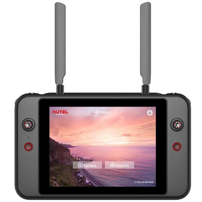
Remote Controller Main Interface
After the remote controller is turned on, it enters the main interface of the Autel Enterprise App by default.
In the main interface of the Autel Enterprise App, slide down from the top of the touch screen or slide up from the bottom of the touch screen to display the system status notification bar and navigation keys, and click the “Home” button or the “Back” button to enter the “Remote Controller Main Interface”. Swipe left and right on the “Remote Controller Main Interface” to switch between different screens, and enter other applications as needed.

Fig 4-11 Remote Controller Main Interface
Table 4-7 Remote Controller Main Interface Details
| No. | Name | Description |
| 1 | Time | Indicates the current system time. |
| 2 | Battery Status | Indicates the current battery status of the remote controller. |
| 3 | Wi-Fi Status | Indicates that Wi-Fi is currently connected. If not connected, the icon is not displayed. You can quickly turn on or off the connection to Wi-Fi by sliding down from anywhere on the “Remote Controller Interface” to enter the “Shortcut Menu”. |
| 4 | Location Info | Indicates that location information is currently enabled. If not enabled, the icon is not displayed. You can click “Settings” to enter the “Location Information” interface to quickly turn on or off location information. |
| 5 | Back Button | Click the button to return to the previous page. |
| 6 | Home Button | Click the button to jump to the “Remote Controller Main Interface”. |
| 7 | “Recent apps” Button | Click the button to view all background programs currently running and take screenshots. |
| Press and hold the application to be closed and slide up to close the application. Select the interface where you want to take a screenshot, and click the “Screenshot” button to print, transfer via Bluetooth, or edit the screenshot. | ||
| 8 | Files | The app is installed in the system by default. Click it to manage 8 Files the files saved in the current system. |
| 9 | Gallery | The app is installed in the system by default. Click it to view the images saved by the current system. |
| 10 | Autel Enterprise | Flight software. The Autel Enterprise App starts by default Enterprise when the remote controller is turned on. For more information, see “Chapter 6 Autel Enterprise App”. |
| 11 | Chrome | Google Chrome. The app is installed in the system by default. When the remote controller is connected to the Internet, you can use it to browse web pages and access Internet resources. |
| 12 | Settings | The system settings app of the remote controller. Click it to enter the settings function, and you can set the network, Bluetooth, applications and notifications, battery, display, sound, storage, location information, security, language, gestures, date and time, device Name, etc. |
| 13 | Maxitools | The app is installed in the system by default. It supports the log function and can restore factory settings. |
Tip
- The remote controller supports the installation of third-party Android apps, but you need to obtain the installation packages on your own.
- The remote controller has a screen aspect ratio of 4:3, and some third-party app interfaces may encounter compatibility issues.
Table 4-8 List of Pre-installed Apps on the Remote Controller
| No | Pre installed App | Device Compatibility | Software version | Operating System Version |
| 1 | Files | 11 | Android 11 | |
| 2 | Gallery | 1.1.40030 | Android 11 | |
| 3 | Autel Enterprise | 1.218 | Android 11 | |
| 4 | Chrome | 68.0.3440.70 | Android 11 | |
| 5 | Settings | 11 | Android 11 | |
| 6 | Maxitools | 2.45 | Android 11 | |
| 7 | Google Pinyio Input | 4,5.2.193126728-arm64-v8a | Android 11 | |
| 8 | Android keyboard (ADSP) | 11 | Android 11 | |
| / | / | / | / | / |
Tip
Please be aware that the factory version of the Autel Enterprise App may vary depending on subsequent function upgrades.
Slide down from anywhere on the “Remote Controller Interface”, or slide down from the top of the screen in any app to display the system status notification bar, and then slide down again to bring up the “Shortcut Menu”.
In the “Shortcut Menu”, you can quickly set Wi-Fi, Bluetooth, screenshot, screen recording, airplane mode, screen brightness, and remote controller sound.

Fig 4-12 Shortcut Menu
Table 4-9 Shortcut Menu Details
| No | Name | Description |
| 1 | Notification Center | Displays system or app notifications. |
| 2 | Time and Date | Displays the current system time, date, and week of the remote controller. |
| 3 | Wi-Fi | click the “ |
| Screenshot | Click the ’ |
|
| Screen Recor Start | After clicking on the |
|
| Airplane mode | Click the |
|
| 4 | Screen brightness Adjustment | Drag the slider to adjust the screen brightness. |
| 5 | Volume Adjustment | Drag the slider to adjust the media volume. |
Frequency Pairing With the Remote Controller
Using the Autel Enterprise App
Only after the remote controller and the aircraft are paired can you operate the aircraft using the remote controller.
Table 4-10 Frequency Pairing Process in the Autel Enterprise App
| Step | Description | Diagram |
| 1 | Turn on the remote controller and the aircraft. After entering the main interface of the Autel Enterprise App, click 88″ in the upper-right corner, click ” |
 |
| 2 | After a dialog box pops up, double- T, ST click on the smart battery power 2button on the aircraft to complete the frequency pairing process with the remote controller. |  |
Note
- The aircraft included in the aircraft kit is paired with the remote controller provided in thekit at the factory. No pairing is required after the aircraft is powered on. Normally, after completing the aircraft activation process, you can directly use the remote controller to operate the aircraft.
- If the aircraft and the remote controller become unpaired due to other reasons, please follow the above steps to pair the aircraft with the remote controller again.
Important
When pairing, please keep the remote controller and the aircraft close together, at most 50 cm apart.
Using Combination Keys (For Forced Frequency Pairing)
If the remote controller is turned off, you can perform forced frequency pairing. The process is as follows:
- Press and hold the power button and the take-off/return-to-home button of the remote controller at the same time until the battery level indicators of the remote controller blink quickly, which indicates that the remote controller has entered the forced frequency pairing state.
- Make sure that the aircraft is turned on. Double-click on the power button of the aircraft, and the front and rear arm lights of the aircraft will turn green and blink quickly.
- When the front and rear arm lights of the aircraft and the battery level indicator of the remote controller stop blinking, it indicates that the frequency pairing is successfully done.
Selecting Stick Mode
Stick Modes
When using the remote controller to operate the aircraft, you need to know the current stick mode of the remote controller and fly with caution.
Three stick modes are available, that is, Mode 1, Mode 2 (default), and Mode 3.
Mode 1

Fig4-13 Mode 1
Table 4-11 Mode 1 Details
| Stick | Move up/Down | Move left/Right |
| Left command stick | Controls the forward and backward movement of the aircraft | Controls the heading of the aircraft |
| Right stick | Controls the ascent and descent of the aircraft | Controls the left or right movement of the aircraft |
Mode 2

Fig 4-14 Mode 2
Table 4-12 Mode 2 Details
| Stick | Move up/Down | Move left/Right |
| Left command stick | Controls the ascent and descent of the aircraft | Controls the heading of the aircraft |
| Right stick | Controls the forward and backward movement of the aircraft | Controls the left or right movement of the aircraft |
Mode 3

Fig 415 Mode 3
Table 4-13 Mode 3 Details
| Stick | Move up/Down | Move left/Right |
| Left command stick | Controls the forward and backward movement of the aircraft | Controls the left or right movement of the aircraft |
| Right stick | Controls the ascent and descent of the aircraft | Controls the heading of the aircraft |
![]() Warning
Warning
- Do not hand over the remote controller to persons who have not learned how to use the remote controller.
- If you are operating the aircraft for the first time, please keep the force gentle when moving the command sticks until you are familiar with the operation.
- The flight speed of the aircraft is proportional to the degree of the command stick movement. When there are people or obstacles near the aircraft, please do not move the stick excessively.
Setting Stick Mode
You can set the stick mode according to your preference. For detailed setting instructions, see * 6.5.3 RC Settings” in Chapter 6. The default stick mode of the remote controller is “Mode 2”.
Table 4-14 Default Control Mode (Mode 2)
| Mode 2 | Aircraft flight status | Control Method |
| Left command stick Move up or Down.
|
 |
|
| Left command stick Move left or right
|
 |
|
| Right Stick | ||
| Move up or Down
|
 |
|
| Right Stick Move Left or Right
|
 |
|


Note
When controlling the aircraft for landing, pull the throttle stick down to its lowest position. In this case, the aircraft will descend to an altitude of 1.2 meter above the ground, and then it will perform an assisted landing and automatically descend slowly.
Starting/Stopping the Aircraft Motor
Table 4-15 Start/Stop the Aircraft Motor
| Process | Stick | Description |
| Start the aircraft motor when the aircraft is powered on |   |
Power on the aircraft, and the aircraft will & automatically perform a self-check (for about 30 seconds). Then simultaneously move the left and right sticks inward or P / \ outward for 2 seconds, as shown in the ) & figure, to start the aircraft motor. |
 |
When the aircraft is in landing state, pull the l throttle stick down to its lowest position, as shown in the figure, and wait for the aircraft to land until the motor stops. | |
| Stop the aircraft motor when the aircraft is landing | |
When the aircraft is in landing state, simultaneously move the left and right sticks inward or outward, as shown in the figure, ) I\ until the motor stops. |
![]() Warning
Warning
- When taking off and landing the aircraft, stay away from people, vehicles, and other moving objects.
- The aircraft will initiate a forced landing in case of sensor anomalies or critically low battery levels.
Remote Controller Keys
Custom Keys C1and C2
You can customize the functions of the C1 and C2 custom keys according to your preferences. For detailed setting instructions, see “6.5.3 RC Settings” in Chapter 6.

Fig 4-16 Custom Keys C1 and C2
Table 4-16 C1 and C2 Customizable Settings
| No. | Function | Description |
| 1 | Visual Obstacle Avoidance On/Off | Press to trigger: turn on/off the visual sensing system. When this function is enabled, the aircraft will automatically hover when it detects obstacles in the field of view. |
| 2 | Gimbal Pitch Recenter/45”/Down | Press to trigger: switch the gimbal angle.
|
| 3 | Map/image Transmission | Press to trigger: switch the map/image transmission view. |
| 4 | Speed mode | Press to trigger: switch the flight mode of the aircraft. For more information, see “3.8.2 Flight Modes”” in Chapter 3. |
![]() Warning
Warning
When the speed mode of the aircraft is switched to “Ludicrous”, the visual obstacle avoidance system will be turned off.
Documents / Resources
 |
AUTEL V2 Robotics Remote Control Smart Controller [pdf] Instruction Manual MDM240958A, 2AGNTMDM240958A, V2 Robotics Remote Control Smart Controller, V2, Robotics Remote Control Smart Controller, Remote Control Smart Controller, Control Smart Controller, Smart Controller, Controller |


