Labkotec LC442-12 Labcom 442 Communication Unit

Background
The Labcom 442 communication unit is designed for the remote monitoring of measurements in industrial, domestic and environmental maintenance applications. Typical applications include oil separator alarms, tank surface level measurements, monitoring pumping stations and real estate, and surface and groundwater measurements.
LabkoNet® service is Available on your computer, tablet and mobile phone.
Text Messages Measurement data and alarms sent directly to your mobile phone. Control and setup the device.
Figure 1: Labcom 442’s connections to various systems
The device sends alarms and measurement results as text messages either directly to your mobile phone or to the LabkoNet service to be stored and distributed to other interested parties. You can easily modify the device settings with your mobile phone or by using LabkoNet service.
The Labcom 442 communication unit is available in two versions with different supply voltages. For continuous measurements, and generally when a permanent power supply is available, the natural choice for the supply voltage is 230 VAC. The device is also available with a battery backup in case of power outages.
The other version operates on a 12 VDC supply voltage and is designed for applications including surface and groundwater measurements, where the operating voltage comes from a battery. The device can be put into a mode that consumes extremely little electricity, allowing even a small battery to last as long as a year. Power consumption depends on the set measurement and transmission intervals. Labkotec offers also Labcom 442 Solar for solar powered service. This installation and user’s guide includes instructions for the installation, start-up and use of the 12 VDC version.
General information about the manual
This manual is an integral part of the product.
- Please read the manual before using the product.
- Keep the manual available for the entire duration of the product’s life span.
- Provide the manual to the next owner or user of the product.
- Please report any errors or discrepancies related to this manual before commissioning the device.
Conformity of the product
- The EU declaration of conformity and the product’s technical specifications are integral parts of this document.
- All of our products have been designed and manufactured with due consideration to the essential European standards, statutes and regulations.
- Labkotec Oy has a certified ISO 9001 quality management system and ISO 14001 environmental management system.
Used Symbols
- Safety related Signs and Symbols

- Informative Symbols

Limitation of liability
- Due to continuous product development, we reserve the right to change these operating instructions.
- The manufacturer cannot be held liable for direct or indirect damage caused by neglecting the instructions provided in this manual or directives, standards, laws and regulations regarding the installation location.
- The copyrights to this manual are owned by Labkotec Oy.
Safety and the environment
General safety instructions
- The plant owner is responsible for the planning, installation, commissioning, operation, maintenance and disassembly at the location.
- Installation and commissioning of the device may be performed by a trained professional only.
- Protection of operating personnel and the system is not ensured if the product is not used in accordance with its intended purpose.
- Laws and regulations applicable to the usage or the intended purpose must be observed. The device has been approved for the intended purpose of use only. Neglecting these instructions will void any warranty and absolve the manufacturer from any liability.
- All installation work must be carried out without voltage.
- Appropriate tools and protective equipment must be used during installation.
- Other risks at the installation site must be taken into account as appropriate.
Federal Communication Commission Interference Statement
This device complies with Part 15 of the FCC Rules. Operation is subject to the following two conditions: (1) This device may not cause harmful interference, and (2) this device must accept any interference received, including interference that may cause undesired operation. This equipment has been tested and found to comply with the limits for a Class B digital device, pursuant to Part 15 of the FCC Rules. These limits are designed to provide reasonable protection against harmful interference in a residential installation. This equipment generates, uses and can radiate radio frequency energy and, if not installed and used in accordance with the instructions, may cause harmful interference to radio communications. However, there is no guarantee that interference will not occur in a particular installation. If this equipment does cause harmful interference to radio or television reception, which can be determined by turning the equipment off and on, the user is encouraged to try to correct the interference by one of the following measures:
- Reorient or relocate the receiving antenna.
- Increase the separation between the equipment and receiver.
- Connect the equipment into an outlet on a circuit different from that to which the receiver is connected.
- Consult the dealer or an experienced radio/TV technician for help.
FCC Caution:
- Any changes or modifications not expressly approved by the party responsible for compliance could void the user’s authority to operate this equipment.
- This transmitter must not be co-located or operating in conjunction with any other antenna or transmitter.
ISED statement:
This product meets the applicable Innovation, Science and Economic Development Canada technical specifications.
Maintenance
The device must not be cleaned with caustic fluids. The device is maintenance-free. However, to quarantee perfect operation of the complete alarm system, check the operation at least once a year.
Transport and storage
- Check the packaging and its content for any possible damage.
- Ensure that you have received all the ordered products and that they are as intended.
- Keep the original package. Always store and transport the device in the original packaging.
- Store the device in a clean and dry space. Observe the permitted storage temperatures. If the storage temperatures have not been presented separately, the products must be stored in conditions that are within the operating temperature range.
Installation in connection with intrinsically safe circuits
Installation of the intrincically safe power circuits of the devices is permitted in potentially explosive zones, whereby, in particular, safe separation from all non-intrinsically safe power circuits must be guaranteed. The intrinsically safe current circuits must be installed according to valid setup regulations. Fot the interconnection of the instrinsically safe field devices and the intrinsically safe power circuits of the associated devices, the respective maximum values of the field device and the associated device with regard to explosion protection must be observed (proof of intrinsic safety). EN 60079-14/IEC 60079-14 must be observed.
Repair
The device may not be repaired or modified without the manufacturer’s permission. If the device exhibits a fault, it must be delivered to the manufacturer and replaced with a new device or one repaired by the manufacturer.
Decommissioning and disposal
The device must be decommissioned and disposed of in compliance with local laws and regulations.
Installation
Structure and Installation of the Device Enclosure
- Labcom 442 device enclosure is wall-mounted. Its mounting holes are located on its back plate underneath the cover’s mounting holes.
- Power feed and relay connectors are located under a protective cover, which must be removed for the duration of the connection work and reinstalled after all cables have been connected. The terminals for external connections are separated by partitions, which must not be removed.
- The cover of the enclosure should be tightened so that its edges come into contact with the back plate. The enclosure’s protection class is IP65. Any extra through holes must be plugged before the device is taken into use.
- The device includes a radio transmitter.
- A minimum separation distance of 0.5 cm must be maintained between the user’s body and the device, including the antenna during body-worn operation to comply with the RF exposure requirements in Europe.

- SUPPLY VOLTAGE 12 VDC
Connects to the + and -terminals of the device. - FUSE 1 AT
- RELAY 1
- 5 = change-over contact
- 6 = normally-open contact
- 7 = normally-closed contact
- RELAY 2
- 8 = change-over contact
- 9 = normally-open contact
- 10 = normally-closed
- DIGITAL INPUTS, x4 terminals 11..18
- ANALOG INPUTS, x4 terminals 19..30
- TEMPERA TURE MEASUREMENT SELECTION
The temperature measurement is selected by jumper S300, which is set to ‘2-3’. Connect temperature measurement to analog input 4. - Solar panel connector
- Digital input 3
- Active sensor
- Temperature measurement
- Charge controller for solar panel (optional) Installation dimensions 160 mm x 110 mm
Connecting the Sensors
Figure 3: Connecting the sensors
Labcom 442 has four 4 to 20 mA analog inputs. A supply voltage of around 24 VDC (+Us) is available from the device for passive two-wire transmitters (pass. 2W). The input impedance of channels 1 to 3 is 130 to 180 Ω and of channel 4 150 to 200 Ω.
Connecting the Supply Voltage
The nominal supply voltage of the device is 12 VDC (9…14 VDC). The maximum current is 850mA. The voltage is supplied to the line connector marked Supply 9…14VDC (cf. figure Kuva:581/Labcom 442 – Rakenne ja liitynnät). The device has a 1 AT distribution fuse (5 x 20 mm, glass tube).
- Battery Backup
The device is also available with a battery backup in case of power outages. The battery is connected to the connector in the top of the device circuit board. We recommend fastening the battery using a two-sided sticker (Figure 4).
Figure 4: Conncting the battery backup to Labcom 442.
Labcom 442 constantly charges the battery at a low current, always keeping the battery operational. Should a power outage occur, Labcom 442 will send an alarm message “Power Failure” to the set phone numbers and continue working for one to around four hours, depending on, for example, the number of measurements connected to it and the temperature of the environment.- 1 channel: 3 h
- 2 channels: 2,5 h
- 3 channels: 1,5 h
- 4 channels: 1,0 h
Table 1: Battery life with different measurements
The battery life indicated in 1 has been measured using a constant 20 mA current in the measurements. This means that in reality, battery life is often longer than indicated here. The values in the table are worst-case values. Once supply voltage is restored, the device will send the message “Power OK”. After a power outage, the battery will be recharged to its full capacity in a couple of days. Use only batteries supplied by Labkotec Oy.
Connecting Temperature Measurements
- You can connect one temperature measurement to the device to the analog input 4. An NTC thermistor is used as the temperature sensor, connected to connectors 28 and 30 as per Kuva:581/Labcom 442 – Rakenne ja liitynnät. Jumper S300 must be set to position ‘2-3’.
- Temperature can be measured only using analog input 4.
- The measurement accuracy is +\- 1°C in temperatures from -20 °C to +50 °C and +\- 2 °C in temperatures from -25 °C to +70 °C.
- Use only temperature sensors supplied by Labkotec Oy.
- See also temperature measurement settings in section : 4 .
Connecting Digital Inputs
Labcom 442 features four digital inputs of the current sinking type. The device provides them with a 24 VDC supply voltage with the current limited to around 200 mA. The power supply and current limit are shared by all digital and analog inputs. The device can calculate the pull times and pulses of digital inputs. The maximum frequency of the pulses is about 100 Hz.
Connecting Relay Controls
Labcom 442 features two relay outputs equipped with changeover contacts that can be used for various control applications (cf. Figure Kuva:581/Labcom 442 – Rakenne ja liitynnät). The relays can be controlled by text messages or by using LabkoNet. The Labcom 442 also has internal functions for the use of relays.
Cabling
In order to maintain a sufficient level of protection against interference, we recommend using screened instrumentation cabling and, for the analog inputs, double-jacket cabling. The device should be installed as far as possible from units containing relay controls, and other cabling. You should avoid routing input cabling closer than 20 cm from other cabling. Input and relay cabling must be kept separate from measurement and communications cabling. We recommend using single-point earthing.
Installing the SIM Card
- Labcom 442 works on most common 2G, LTE, LTE-M and Nb-IoT connections.
- LabkoNet devices come with a pre-installed Micro-SIM card, which cannot be replaced.
- If you want to use SMS messaging, you need to make sure that your subscription supports SMS messaging.
- Install the Micro-SIM(3FF) card you acquired for the Labcom 442 communication unit in your own mobile phone and make sure that sending and receiving text messages works.
- Deactivate the PIN code query from the SIM card.
- Insert the SIM card into holder as shown in Figure 5. Check the correct position of the SIM card from the guide picture of printed circuit board and push the SIM card in this position to the bottom of holder.

Connecting an external antenna
By default, the device uses an internal antenna. But it is also possible to connect an external antenna. The type of antenna connector on the PCB is MMCX female, so the external antenna connector must be of type MMCX male.
Operation of LED lights
The LED indicator lights of the device are marked on the circuit board in square frames. There is also identifier text next to them.
| Circuit board identifier | Explanation of the LED identifier |
Functional description of the LED |
|
PWR |
PoWeR – green 230VAC version voltage status |
LED lights up when the voltage is 230VAC. |
| MPWR | Radio Module PoWeR – green Radio module voltage state | Lights up when the modem voltage is on. |
|
AIE |
Analog Input Error – red Analogue input current error light | AIE blinks if input current in any analog input A1…A4 is > 20.5 mA, otherwise AIE is off. |
|
REG |
REGistered in network – yellow
Modem network registration status |
REG off – Modem is not registered in network.
REG blinks – Modem is registered but signal strength is < 10 or signal strength not yet received. REG glows continuously – registered and signal strength is > 10 |
|
RUN |
Data RUN – green Activity of the modem | RUN blinks at interval of 1s – normal state RUN blinks approx. interval of 0.5 s – modem data transmission or reception is active. |
|
BAT |
BATtery Status – yellow Status of the backup battery | BAT blinks – battery charger is on
BAT glows – Backup battery is charged full. BAT is off – no backup battery installed. |
|
NETW |
NETWork – yellow Operator’s network type |
Operator network type, indicator state depends on radiotechnology as follows:
LTE /NB-Iot home – glows continuously. 2G home – blinks once in 2 s period. LTE/NB-Iot roaming – blinks once in 1s period. 2G roaming – blinks twice in 2s period. |
| IOPWR | Input-Output-PoWeR – green Analog output voltage status | Glows when analog input field voltage supply is on |
| R1 | Relay1 – orange Status light of relay 1 | Glows when relay R1 is energized. |
| R2 | Relay2 – orange Status light of relay 2 | Glows when relay R2 is energized. |
OPERATING PRINCIPLE
Operation
- Labcom 442 sends alarms and measurement results as text messages, either directly to your mobile phone, or to the LabkoNet® server.
- You can define the time interval at which measurement results are sent to the desired phone numbers. You can also query measurement results with a text message.
- In addition to the aforementioned sending interval setting, the device will take readings from connected sensors at set intervals, and send an alarm, if a reading is not within the set upper and lower limits. A status change in digital inputs also causes an alarm text message to be sent.
- You can modify the device settings and control the relays with text messages.
Setup
You can setup the Labcom 200 fully via text messages. Setup a new device as follows:
- Set the operator phone numbers
- Set the end-user phone numbers
- Set the device’s name and the parameters for the measurements and digital inputs
- Set the alarm message texts
- Set the time
Labcom 442 and Mobile Phones
The figure below describes the messages sent between the user and the Labcom 442 communication unit. The messages are sent as text messages, described in more detail later in this document.
You can store two kinds of phone numbers on the device:
- End-user phone numbers, to which measurement and alarm information is sent. These numbers can query for measurement results and control the relays.
- Operator phone numbers, which can be used to modify the device settings. Neither measurement nor alarm information is sent to these numbers, but they can query for measurement results and control the relays.
NB! If you wish to receive measurement and alarm information to the same phone number from which you wish to modify device settings, you must set the number in question as both an end-user and an operator phone number.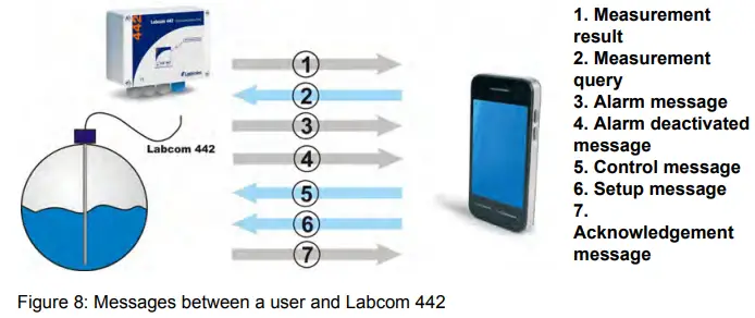
Labcom 442 and LabkoNet®
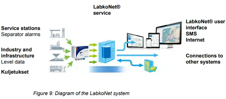
- Labcom 442 can be connected to the Internet-based LabkoNet® monitoring system. The LabkoNet® system’s benefits when compared to a mobile phone connection include continuous monitoring of the connection and the storing and visual representation of measurement and alarm information.
- Alarm and measurement information received from a measurement point is transmitted via the communication unit to the LabkoNet® service over the mobile phone network. The service receives the information sent by the communication unit and stores it in a database, from which it can later be read, e.g. for reporting purposes.
- The service also checks the data from each measurement channel sent by the device, converts it to the desired format and checks for values not inside the set alarm limits. When alarm conditions are fulfilled, the service will send the alarms to predefined e-mail addresses as an e-mail and phone numbers as a text message.
- The measurement data can be viewed over the Internet at www.labkonet.com using the end-user’s personal user ID, both numerically and graphically with a regular Internet browser.
- LabkoNet also has a wide range of application-specific logic that can be used with the Labcom 442 product.
COMMANDS AND DEVICE REPLIES
Phone Numbers
- End-user and Operator Phone Numbers
The setting message for end-user and operator phone numbers contains the following fields, separated by spaces.Fiels Description TEL or OPTEL
TEL = Message code for an end-user phone number setting message OPTEL = Message code for an operator phone number setting message
<number>
Phone number in an international format You can send all phone numbers accepted by the device in one message (assuming they fit in one text message = 160 characters).
You can set ten (10) end-user phone numbers. You can set five (5) operator phone numbers.
The device will store the numbers in order in the first available memory
slots. If the message contains more than ten phone numbers or the memory slots are already full, any extra phone numbers will not be stored.
The sample message
TEL +35840111111 +35840222222 +35840333333
adds three end-user phone numbers to the device. The device’s reply to this message (with one previously set end-user phone number already stored in the memory) is:
<device name> TEL 1:+3584099999 2:+35840111111 3:+35840222222 4:+35840333333
i.e. the device’s reply is of the following format:
<device name> TEL <memory_slot_number>:<number>
The message will contain as many memory slot/number pairs as there are numbers stored in the memory.
You can query the end-user phone numbers set for the device with the following command:
TEL
You can query the operator phone numbers with the following command:
OPTEL - Delete End-user and Operator Phone Numbers
You can delete phone numbers set on the device with end-user and operator phone number deletion messages. The message contains the following fields, separated by spaces.Field Description DELTEL = Message code for an end-user phone number deletion DELTEL or message DELOPTEL DELOPTEL = Message code for an operator phone number deletion message <memory_slot_
The memory slot of a phone number stored on the device. You can find nouumt btheerm> emory slots with TEL and OPTEL queries. If you enter more than one memory slot number, you must separate them by spaces. The sample message
DELTEL 1 2
deletes the end-user phone numbers stored in the device’s memory slots 1 and 2. The third end-user phone number stored in the memory remains in its old slot.
The device’s reply to the previous message recounts the remaining numbers.
<device name> TEL 3:+3584099999
Basic Settings During Commissioning
- Device or Site Name
You can use the device name message to set the device’s name, displayed henceforth in the beginning of all messages. The message contains the following fields, separated by spaces.Field Description NAME Message code for a Device Name message. <device name> Device or site name. Maximum length 20 characters. The sample message
NAME Labcom442
will be acknowledged by the device with the following message
Labcom442 NAME Labcom442
i.e. the device’s reply is of the following format:
<device name> NAME <device name>
NB! The Device Name setting may also include spaces, e.g.
NAME Kangasala Labkotie1
You can query the name of the device with the following command:
NAME - Transmission Interval and Time of Measurement Message
You can set the transmission interval and times for the measurement messages sent by the device with this command. The message contains the following fields, separated by spaces.Field Description TXD Message code for a transmission interval and time message. <interval> The interval between measurement message transmissions in days. <time>
The transmission times for measurement messages in hh:mm format, where hh = hours (NB: 24-hour clock) mm = minutes
You can set a maximum of six (6) transmission times per day in the
device. They must be separated by spaces in the setup message.
The sample message
TXD 1 8:15 16:15
will set the device to send its measurement messages every day at 8:15 and 16:15. The device’s reply to this message would be:
Labcom442 TXD 1 8:15 16:15
i.e. the device’s reply is of the following format:
<device name> TXD <interval> <time>
You may query the device for the transmission interval with the following command:
TXD
You can delete transmission times by setting the time to 25:00. - Deleting the transmission times of measurement messages
This command can be used to clear the transmission times of measurement messages completely from memory.Field Description DELTXD Measurement message transmission deleting identifier. The device’s reply to this message would be:
TXD 0
- Time
You can set the time of the device’s internal clock with a time setup message. The message contains the following fields, separated by spaces.Kenttä Kuvaus CLOCK Message code for a time setup message. <date>
Enter the date in dd.mm.yyyy format ,where dd = day mm = month
yyyy = year
<time>
Enter the time in hh:mm format, where hh = hours (NB: 24-hour clock) mm = minutes
The sample message
CLOCK 27.6.2023 8:00
would set the device’s internal clock to 27.6.2023 8:00:00 The device will reply to the time setup message as follows:
<device name> 27.6.2023 8:00
You can query the device’s time by sending the following command:
CLOCK - Automatic local time update from the operator network
The device will automatically update the time from the operator’s network when it is connected to the network. The default time zone is UTC. If you want the time to be updated to local time, this can be activated as follows:Field Description AUTOTIME Set the time message tag text. <state> 0 = time zome is UTC.1 = time zome is local time. The sample message
AUTOTIME 1
to set the device to update to local time. The device responds to the time setting with a message
<device name> AUTOTIME 1
The setting takes effect after restarting the device or modem. - Signal Strength Query
You can query the signal strength of the modem with the following command:
CSQ
The device’s reply is of the following format:
<laitenimi> CSQ 25
Signal strength may vary between 0 and 31. If the value is below 11, the connection may not be sufficient for transmitting messages. Signal strength 99 means that signal strength has not yet been received from the modem.
Measurement Settings
- Measurement Setup
You can set up names, scaling, units, and alarm limits and delays of measurements connected to the analog inputs of the device with a measurement setup message. The message contains the following fields, separated by spaces.Field Description AI<n>
Message code for a measurement setup message. The code indicates a physical measurement input for the device. The possible values are AI1, AI2, AI3 and AI4.
<AIn txt>
Freeform text defined as the name of a measurement. The name of the measurement is used as the measurement identifier in measurement and alarm messages. Cf. for example Measurement Message. <4mA> The measurement value provided by the device when the sensor current is 4 mA. (scaling) <20mA> The measurement value provided by the device when the sensor current is 20 mA. (scaling) <unit> The unit of measurement (after scaling). <lower limit> The value for the lower limit alarm (according to the scaling performed above). Cf. also the setting of the lower limit alarm message in section 6 <upper limit> The value for the upper limit alarm (according to the scaling performed above). Cf. also the setting of the upper limit alarm message in section 6 <delay>
The alarm delay for the measurement in seconds. For the alarm to be activated, the measurement must remain above or below the alarm limit for the duration of the entire delay. The longest possible delay is 34464 seconds (~9 h 30 min). The sample message
AI1 Well level 20 100 cm 30 80 60
sets up a measurement connected to analog input 1 as follows:- The name of the measurement is Well_level
- The value 20 (cm) corresponds with the sensor value 20 mA
- The value 100 (cm) corresponds with the sensor value 20 mA
- The measurement unit is cm
- The lower limit alarm is sent when the well level is below 30 (cm)
- The upper limit alarm is sent when the well level is above 80 (cm)
- The alarm delay is 60 s
- Temperature Measurement Setup
You can connect an NTC-type temperature sensor to analog input 4. You can enable temperature measurement with the following command:
AI4MODE 2 0.8
Additionally, the jumper S300 next to channel 4 must be put into the correct position.The measurement scaling described in the previous section does not affect the temperature measurement settings apart from measurement unit and the alarm limits. The AI4 command can, therefore, be used to set the unit as C or degC and 0 °C and 30 °C as the alarm limits as follows (delay 60 seconds):
AI4 Temperature 1 1 C 0 30 60 - Measurement Filtering
A measurement value from a single point in time will not be representative of the real value in situations when it is to be expected that the surface level will fluctuate quickly. Filtering from analog inputs is advisable in such cases. A measurement situation described above could happen, for example, in the measurement of a lake’s surface level, where the result will fluctuate several centimeters over a few seconds due to waves.Field Description AI<n>MODE
Message code for the measurement filtering message, where <n> = 1… 4. The code indicates a physical measurement input of the device.
The possible values areAI1MODE, AI2MODE, AI3MODE and AI4MODE
<mode>
Filtering mode. 0 = So-called digital RC filtering is enabled for the analog channel, i.e., the measurement results are modified with filtering factor <par>, which evens the difference between consecutive results.
<par>
The filtering factor. See below. If mode is 0, <par> is the filter factor between 0.01 and 1.0. Maximum filtering is achieved with a value 0.01. No filtering is performed when
<par> is 1.0.
You can define filtering separately for each analog input.
You can define filtering for each analog input with the following command:
AI<n>MODE <mode> <par>
For example, the command
AI1MODE 0 0.8
sets the filtering factor 0.8 for measurement input 1, which evens the difference between consecutive results.
You can query the filtering mode and parameter for each analog input with the following command:
AI<n>MODE
where <n> is the number of the input in question.
The device’s reply is of the following format:
<device name> TXD AI<n>MODE <mode> <par>
NB! If no AI<n>MODE setting has been made for the channel, the default setting will be mode 0 (digital RC filter) with a factor of 0.8. - Hysteresis Setting for Analog Inputs
If you desire, you can set a hysteresis error value for an analog input. The hysteresis error limit is the same for both the lower and upper limits. At the upper limit, alarm is deactivated when the input value has dropped at least the hysteresis value below the alarm limit. The operation at the lower limit is naturally the opposite. You can set the hysteresis error limit with the following message:
AI<n>HYST <hysteresis error limit>
where <n> is the number of the analog input.
Sample message
AI1HYST 0.1
The unit of measurement for the hysteresis error limit is the unit defined for the limit in question. - Setting the Number of Decimals
You can change the number of decimals in decimal numbers in measurement and alarm messages with the following command:
AI<n>DEC <number of decimals 0…9>
For example, you can set the number of decimals for analog input 1 to three with the following message:
AI1DEC 3
The device will acknowledge the setting with the following message:
<device name> AI1DEC 3
Digital Input Settings
- Digital Input Setup
You can set up the digital inputs of the device with a digital input setup message. The message contains the following fields, separated by spaces.Field Description DI<n>
Message code for a digital input setup message. The code indicates a physical digital input of the device. The possible values are DI1, DI2, DI3 and DI4.
<DIn txt>
Freeform text defined as the name of a digital input. The name of the digital input is used as the input identifier in measurement and alarm messages. Cf. for example Measurement Message: 3 <open> The text corresponding to the digital input’s open state. <closed> The text corresponding to the digital input’s closed state. <operating mode>
The operating mode of the digital input 0 = alarm activated upon open status 1 = alarm activated upon closed status
<delay>
Alarm delay in seconds. The longest possible delay is 34464 seconds (~9 h 30 min). NOTE! When the delay of digital input is set to 600 seconds or more and the alarm is activated, delay for alarm de-activation is not the same as for activation. In this case, alarm is de-activated in 2 sec-onds after the input has returned to the inactive state. This makes e.g. supervision of maximum running time of pumps possible.
The sample message
DI1 Door switch open closed 0 20
sets up the device’s digital input 1 as follows:- The device will send an alarm message after 20 seconds from the opening of the door switch connected to digital input 1. The alarm message is in the following format:
<device name> <alarm text> Door switch open - Once the alarm is deactivated, the message is in the following format:
<device name> <alarm deactivated text> Door switch closed
- The device will send an alarm message after 20 seconds from the opening of the door switch connected to digital input 1. The alarm message is in the following format:
- Pulse Counting Settings
You can set up pulse counting for the device’s digital inputs. Set the following parameters to enable counting:Field Description PC<n> Message code for a Pulse Counting message (PC1, PC2, PC3 or PC4).
<pulse counter text> The pulse counter’s name in the device’s reply message.
<unit text> The unit of measurement, for example ‘times’. <divisor> You can set the counter to increase, for example, every 10th or 100th pulse. Set the desired integer between 1 and 65534 as the divisor. <filtering delay> The time the digital input must remain active before a pulse is registered in the counter. The unit of time used is ms, and the delay can be set between 1 and 254 ms. Sample message for enabling pulse counting:
PC3 Pump3_on times 1 100
The device’s reply to this message would be:
<device name> PC3 Pump3_on times 1 100
Sample measurement message from pulse counting:
<device name> Pump3_on 4005 times
You can clear the pulse counter with the following message:
PC<n>CLEAR
for example
PC3CLEAR
You can clear all pulse counters simultaneously with the following message:
PCALLCLEAR - Setting On-time Counters for Digital Inputs
You can set up a counter for digital inputs to count their on-time. The counter will increase every second the digital input is in the “closed” state. The message is of the following format:Field Description OT<n> On-time counter identifier, where <n> is the number of the digital input. <on-time counter text> The name of the counter in a measurement message.
<unit> The unit of measurement in the reply message. <divisor> Divisor used to divide the number in the reply message. sample message in which the divisor of digital input 2 counter is set to one and ‘seconds’ as the unit, and the name of the counter is set to ‘Pump2’:
OT2 Pump2 seconds 1
Note that the unit is only a text field and cannot be used for unit conversion. The divisor is for this purpose.
You can disable the desired counter with the following message:
OT<n>CLEAR
You can disable all counters at once with the following message:
OTALLCLEAR
Relay Output Settings
- Relay Control
You can control the device relays with a relay control message. The message contains the following fields, separated by spaces.Field Description R Message code for a relay control message. R<n>
Relay identifier. Possible values are R1 and R2.
<state>
The desired state of the relay 0 = relay output to “open” state l. “off” 1 = relay output to “closed” state l. “on” 2 = impulse to the relay output
<impulse>
Impulse length in seconds. This setting is meaningful only if the previous setting is 2. However, this field must be included in the message even if no impulse is desired. In such cases, we recommend entering 0 (zero) as the field value.
The sample message
R R1 0 0 R2 1 0 R2 2 20
would set up the device’s relay outputs as follows:- Relay output 1 to the “off” state
- Relay output 2 first to the “on” state and then to the “off” state for 20 seconds
The device will reply to the relay control message as follows:
<device name> R<n> <state> <impulse>
NB! In this case, the reply format differs from replies to other commands.
- Relay control feedback monitoring alarm
A relay conflict alarm can be used to monitor whether the circuits controlled by relays R1 and R2 are active. The control is based on the use of digital inputs, so that when the relay is active the status of the digital input controlling it must be ‘1’, and when the relay is released it must be ‘0’. The control is connected to the digital inputs so that the control feedback for R1 is read from input DI1 and the feedback for relay R2 is read from input DI2.Field Description RFBACK Identifier of the relay feedback message <ch> Relay channel identifier The possible values are 1 (R1/DI1) or 2 (R2/DI2)
<on_off> Conflict alarm selection 0 = Conflict alarm off 1 = Conflict alarm on
<delay> Alarm delay in seconds. The alarm is activated if the status of the digital input controlling the relay is not ‘1’ after a delay. The maximum delay can be 300 s.
Sample message:
RFBACK 1 1 10
switches on the monitoring of the relay output R1 of the device with an alarm delay of 10s.
The status of both relays can also be set at the same time:
RFBACK 1 1 10 2 1 15 , the order of the channels in the message is irrelevant.
The device always returns the setting values for both channels in the setup message:
RFBACK 1 1 10 2 1 15
The monitoring alarm can be disabled by setting the on/off mode to zero, e.g.
RFBACK 1 0 10 - Connecting the relay control to the analogue input
The relays can also be controlled according to the levels of analogue inputs AI1 and AI2. The control is hard-wired to the inputs, with R1 being controlled by analogue input AI1 and relay 2 by input AI2. The relay pulls when the measurement signal is above the upper limit setting for the upper limit delay and releases when the measurement signal falls below the lower limit and remains there continuously for the lower limit delay. The control requires that the channels are set to a scaled measurement range in the ‘Set measurement’ section 3. The lower and upper limit measurement of the relay control follows the scaled range. Rel ay control is not active if surface control is active and 2 pumps are in use. If there is one pump, relay 2 can be used. The structure of the control command is shown below, the parameters should be separated by spaces.Field Description RAI Message code for relay control to the analogue input setup message. <ch> Relay channel identifier Possible values are 1 (R1/AI1) or 2 (R2/AI2)
<lower limit> The measurement signal below the level which the relay will release after the lower limit delay. <lower limit delay> Lower limit delay in seconds. The counter is 32-bit <upper limit> The measurement signal above the level which the relay pulls out after the upper limit delay. <upper limit delay> Upper limit delay in seconds. The counter is 32-bit Sample setup message:
RAI 1 100 4 200 3
relay 1 is set to pull when the value of the measurement signal exceeds 200 for three seconds. The relay releases when the signal has fallen below 100 and has remained there for at least 4 seconds.
Similarly, relay 2 can be set with the message
RAI 2 100 4 200 3
Both relays can also be set with a single message:
RAI 1 2 100 4 200 3 2 100 4 200
This function can be disabled by entering the command
USE AI<ch> , in which case the function of the analogue input changes to like in 4 .
Modem configuration settings
The following modem configuration settings will only take effect after the modem has been reset. The reset does not need to be done after each command, it is sufficient to do it at the end of the configuration. After the radio technology setting the modem is automatically reset, for other commands it is sufficient to reset the modem at the end of the configuration. See paragraph 5
- Choosing radio technology
The radio technologies used by the modem can be configured with a single message.Field Description RADIO Message code for radio technology setup. <technology> RADIO 7 8 9 Sets LTE as the primary network, Nb-IoT second and 2G last. The device responds to a message
RADIO 7,8,9
Setting is active after modem restart.
The current setting can be read with a setting message without parameters.
RADIO
If the use of a radio technology is to be prevented, the corresponding numerical code is omitted from the command. For example, with the command
RADIO 7 9
the modem can be prevented from connecting to the Nb-Iot network, allowing the modem to connect only to the LTE/LTE-M or 2G network.
The following technologies are allowed:
- 7: LTE
- 8: Nb-IoT
- 9: 2G
LTE (7) and 2G (9) are selected by default.
- Operator profile selection
A message can be used to set the modem to a specific operator profileField Description MNOPROF Message code for operator profile setup. <profile number> Profile number of the operator The allowed profile choices are:
- 1: SIM ICCID/IMSI
- 19: Vodafone
- 31: Deutsche Telekom
- 46: Orange France
- 90: Global (tehdas asetus)
- 100: Standard Europe
Example setup message:
MNOPROF 100
The device’s reply wuold be:
MNOPROF 100
Setting is ac tive after modem restart.
The current setting is read with a message without parameters.
MNOPROF
- LTE frequency bands for your modem
The frequency bands of the modem’s LTE network can be set according to the operator’s network.Field Description BANDS LTE Message code for LTE frequency bands setup. <LTE frequency selection> LTE frequency band numbers The supported frequency bands are:
- 1 (2100 MHz)
- 2 (1900 MHz)
- 3 (1800 MHz)
- 4 (1700 MHz)
- 5 (850 MHz)
- 8 (900 MHz)
- 12 (700 MHz )
- 13 (750 MHz)
- 20 (800 MHz)
- 25 (1900 MHz )
- 26 (850 MHz)
- 28 (700 MHz)
- 66 (1700 MHz )
- 85 (700 MHz)
The frequency bands to be used are set in using the command with spaces
BANDS LTE 1 2 3 4 5 8 12 13 20 25 26 28 66
The device responds to the setup message:
LTE 1 2 3 4 5 8 12 13 20 25 26 28 66
Setting is active after modem restart.
NOTE! If the band settings are incorrect, the program will ignore them and select only the supported frequencies from the message.
The current setting is read with a setting message without parameters.
BANDS LTE
- Nb-IoT frequency bands of the modem
The frequency bands of the Nb-IoT network can be configured like those of the LTE network.Field Description BANDS NB Message code for Nb-IoT frequency bands setup. <Nb-IoT frequency selection> Nb-IoT frequency band numbers. The supported frequency bands are the same as for the LTE network and the setup is the same as for the LTE network:
BANDS NB 1 2 3 4 5 8 20
The device would respond:
NB 1 2 3 4 5 8 20
Setting is active af ter modem restart.
The current setting is read with a setting message without parameters.
BANDS NB - Reading the modem’s basic radio settings
Field Description BANDS Message code for modem’s basic radio settings. The message allows you to read the basic settings in one go, in response to which the selected radio technologies, operator name, current network, LTE and Nb-IoT bands used, operator profile and LAC and CI codes indicating the location of the modem at the cellular level are printed.
RADIO 7 8 9 OPERATOR “Te lia FI” LTE
LTE 1 2 3 4 5 8 12 13 20 25 26 28 66
NB 1 2 3 4 5 8 20
MNOPROF 90
LAC 02F4 C I 02456 - Name of the network operator and reading the type of radio network
Field Description OPERATOR Message code for name of the network operator and the type of radio network. The device responds with a message containing the network name used by the operator, the radio technology used
LTE/ NB/ 2G and the type of network HOME or ROAMING.
OPERATOR “Telia FI” LTE HOME - Resetting the modem
The modem needs to be restarted after settings such as radio bands, radio technology and operator profile.Field Description MODEMRST Message code for resetting the modem. The device responds:
RESTARTING MODEM…
Alarms
- Alarm Texts
You can define alarm texts that the device includes at the beginning of the messages sent when an alarm is activated and deactivated with an alarm text setup message. Both cases have their own text. The message contains the following fields, separated by spaces.Field Description ALTXT Message code for an alarm text setup message. <alarm on>. Text sent when an alarm is activated, followed by a period. <alarm off> Text sent when an alarm is deactivated. The alarm text (either <alarm on> or <alarm off>)>) is inserted in the alarm messages between the device name and the cause of the alarm. See more information in section Alarm Message 8.
Sample alarm text setup message:
ALTXT ALARM. ALARM DEACTIVATED
The device’s reply to this message would be:
<device name> ALTXT ALARM. ALARM DEACTIVATED
The corresponding alarm message would then be:
Labcom442 ALARM <measurement name> … - Measurement Upper and Lower Limit Alarm Texts
You can set up the text indicating the cause of an alarm and alarm deactivated messages with this command. For example, when a measurement value is lower than the lower limit alarm value, the device will send the corresponding lower limit alarm text in the alarm message. The message contains the following fields, separated by spaces.Field Description AIALTXT Message code for the measurement limit alarm text setup message. <lower limit txt>. The text sent when a lower limit alarm is activated or deactivated, followed by a period. The default value of this field is Low Limit. <upper limit txt> The text sent when an upper limit alarm is activated or deactivated. The default value of this field is High Limit. The measurement upper and lower limit alarm texts are inserted in the alarm message after the name of the measurement or digital input that caused the alarm. See more information in section Alarm Message 8
Sample setup message:
AIALTXT Lower limit. Upper limit
The device’s reply to this message would be:
<device name> AIALTXT Lower limit. Upper limit
The corresponding alarm message would then be:
Labcom442 ALARM Measurement1 Upper limit 80 cm - Alarm Message Recipients
You can define which messages are sent to whom with this command. As a default, all messages are sent to all users. The message contains the following fields, separated by spaces.Field Description ALMSG Message code for the alarm message recipient’s message. <memory slot> The memory slot of a phone number stored on the device (you can check the slots with a TEL query). <messages>
Which messages are sent, coded as follows: 1 = only alarms and measurements 2 = only deactivated alarms and measurements
3 = alarms, deactivated alarms and measurements 4 = only measurements, no alarm messages
8 = neither alarm messages nor measurements
The sample message
ALMSG 2 1
would set the messages sent to the end-user phone number stored in memory slot 2 as alarms and measurements.
The device’s reply to the sample message would be as follows (containing the phone number stored in memory slot 2):
Labcom442 ALMSG +3584099999 1
i.e. the device’s reply is of the following format:
<device name> ALMSG <phone number stored in memory slot> <messages>
You can query the alarm recipient information for all end-user phone numbers with the following command:
ALMSG
Other Settings
- Enable Channel
You can enable measurement channels with an enable channel message. Note, that measurement channels set up with a Measurement Setup or Digital Input Setup message are automatically enabled.
Including the message code, the message may include the following fields separated by spaces.Field Description USE Message code for an enable channel message. AI<n>
The number of the analog channel to be enabled. One message may include all analog channels. The possible values are AI1, AI2, AI3 and AI4
DI<n>
The number of the digital input to be enabled. One message may include all digital inputs. The possible values are DI1, DI2, DI3 and DI4
The device will reply to the setup message and a query (just USE) by sending the new settings in the same format as the setup message, adding the device name to the beginning.
You can enable the device’s measurement channels 1 and 2 and digital inputs 1 and 2 with the following sample message:
USE AI1 AI2 DI1 DI2 - Disable Channel
You can disable measurement channels already defined and set up with a disable channel message. Including the message code, the message may include the following fields separated by spaces.Field Description DEL Message code for a disable channel message. AI<n>
The number of the analog channel to be disabled. One message may include all analog channels. The possible values are AI1, AI2, AI3 and AI4
DI<n>
The number of the digital input to be disabled. One message may include all digital inputs. The possible values are DI1, DI2, DI3 and DI4
The device will reply to the setup message by sending the identifiers of all channels in use, adding the device name to the beginning.
You can disable the device’s measurement channels 3 and 4 and digital inputs 1 and 2 with the following sample message:
DEL AI3 AI4 DI1 DI2
The device will reply with the enabled channels, for example
<device name> USE AI1 AI2 DI3 DI4
The device will also reply to just the DEL command by reporting the enabled channels. - Low Operating Voltage Alarm Value
The device monitors its operating voltage. The 12 VDC version monitors the operating voltage directly from the source, e.g. a battery; the 230 VAC version monitors the voltage after the transformer. The low operating voltage alarm value sets the voltage level below which the device sends an alarm. The message contains the following fields, separated by spaces.Field Description VLIM Message code for a Low Operating Voltage Alarm Value message. <voltage> The desired voltage, accurate to one decimal point. Use a period as the decimal separator. The device’s reply is in the following format:
<device named> VLIM <voltage>
For example, when you set up the operating voltage alarm as follows:
VLIM 10.5
the device will send an alarm, if the operating voltage drops below 10.5 V.
The alarm message is of the following format:
<device name> Low battery 10.5
You can query the low operating voltage alarm setting with the following command:
VLIM - Setting the voltage of the mains-powered device backup battery
The mains voltage device monitors the mains voltage level and when the voltage drops below a certain value, this is interpreted as a loss of mains voltage and the device sends a mains voltage alarm. This setting allows to set the voltage level at which the mains voltage is interpreted as having been removed. The default value is 10.0V.
The message contains the following fields, separated by a space.Field Description VBACKUP Backup battery voltage setting message. <voltage> The desired voltage value in volts to one decimal place. The separator between the integer and decimal parts is a dot. Laitteen vastaus viestiin on muotoa
<device name> VBACKUP <voltage>
For example, when setting
VBACKUP 9.5
then the device interprets the mains voltage as having been removed when the voltage in the operating voltage measurement falls below 9.5V. To query a setting, use the command
VBACKUP
NOTE! The setting value should always be slightly higher than the maximum possible voltage of the backup battery (e.g. + 0.2…0.5V). This is because the device compares the set value with the operating voltage value and, if it falls below the VBACKUP setting, interprets that the operating voltage has been removed. If the value is equal to the voltage of the backup battery, a mains voltage alarm is generated. - Battery Voltage Query
You can query the battery voltage with the following command:
BATVOLT
The device’s reply is of the following format:
<device name> BATVOLT <value> V - Software Version
You can query the software version of the device with the following command:
VER
The device’s reply to this message would be:
<device name> LC442 v<version> <date>
For example
Device1 LC442 v1.00 Jun 20 2023 - Clearing Text Fields
You can clear text fields defined with messages by setting their value as the ‘?’ character. For example, you can clear a device name with the following message:
NAME ? - Resetting Labcom 442 device
Kenttä Kuvaus SYSTEMRST Command for Resetting Labcom 442 device
MESSAGES SENT TO END-USERS BY THE DEVICE
This section describes the messages sent by the standard software version of the Labcom 442 communication unit. If other, customer-specific messages have been defined, they are described in separate documents.
- Measurement Query
You can query the device for measurement values and states of the digital inputs with the following command:
M
The device’s reply message will include the values of all enabled channels. - Measurement Result Message
Measurement Result Messages are sent to end-user phone numbers either timed, based on the Transmission Interval setting 2 or as a reply to a Measurement Query text message 7 . The measurement result message contains the following fields separated by spaces. Only the information of channels enabled on the device is shown. A comma is used as a separator between all measurement results and digital input states (except the last one).
| Field | Description | |
| <device name> | If a name has been defined for the device, it is inserted at the beginning of the message. | |
| <AIn txt> <value>
<unit>, |
The name of the measurement channel, the result, and the unit for each result. The data from different measurement channels are separated by commas. | |
| <AIn name> | The name defined for measurement n. | |
| <value> | The result of measurement n. | |
| <unit> | The unit for measurement n. | |
| <DIn name> <state>, | The name and state of each digital input. The data for different digital inputs are separated by commas. | |
| <DIn name> | The name defined for a digital input. | |
| <state> | The state of the digital input. | |
|
<pulse counter name> <number of pulses> <unit> |
If the pulse counter for a digital input has been enabled, its value is displayed in this field. The data for different counters are separated by commas. | |
| <pulse counter name> | The name of the counter. | |
| <number of pulses> | The number of pulses divided by the divisor. | |
| <unit> | The unit of measurement. | |
|
<on-time counter name> <time> <unit> |
If the on-time counter for a digital input has been enabled, its value is displayed in this field. The data for different counters are separated by commas. | |
| <on-line counter name> | The name of the counter. | |
| <time> | The on-time of the digital input | |
| <unit> | The unit of measurement. | |
The sample message
Labcom442 Well level 20 cm, Weighing 10 kg, Door switch closed, Door buzzer silent
indicates that a device named Labcom442 has measured the following:
- Well_level (e.g. Ai1) was measured as 20 cm
- Weighing (e.g. Ai2) was measured as 10 kg
- Door_switch (e.g. Di1) is in the closed state
- Door_buzzer (e.g. Di2) is in the silent state
Note! If no device name, measurement name and/or unit has been defined, nothing will be printed in their place in the measurement message.
- Comma Settings in Measurement Messages
If you wish, you can remove commas from end user messages (mainly measurement messages) sent by the device. You can use the following messages to make these settings.
Commas not in use:
USECOMMA 0
Commas in use (normal setting):
USECOMMA 1
Alarm Message
Alarm messages are sent to end-user phone numbers but not to operator phone numbers. An alarm message includes the following, separated by spaces.
| Field | Description |
| <device name> | If a name has been defined for the device with the NAME command, it is inserted at the beginning of the message. |
| <alarm on> | The alarm text defined with the ALTXT command. e.g. HÄLYTYS. |
| <AIn name>
or <DIn name> |
The name of the measurement or digital input that caused the alarm. |
| <cause> | The cause of the alarm (lower or upper limit alarm) or the state text of the digital input. |
| <measurement value>
and <unit> |
If the alarm was caused by a measurement, the measurement value and unit will be included in the alarm message. This field is not included in alarm messages caused by a digital input. |
Sample message 1:
ALARM Well level lower limit 10 cm
indicates the following:
- The well level has been measured to be below the lower limit.
- The measurement result was 10 cm.
Sample message 2 (Labcom442 defined as the device name):
Labcom442 ALARM Door switch open
indicates that the alarm was caused by the opening of the door switch.
Note! If no device name, alarm text, name for the alarm or digital input and/or unit has been defined, nothing will be printed in their place in the alarm message. It is therefore possible that the device will send a measurement alarm message containing only the measurement value, or a digital input alarm message containing nothing.
Alarm Deactivated Message
Alarm Deactivated messages are sent to end-user phone numbers but not to operator phone numbers.
An alarm deactivated message includes the following, separated by spaces.
| Field | Description |
| <device name> | If a name has been defined for the device with the NAME command, it is inserted at the beginning of the message. |
| <alarm off> | The Alarm Deactivated text defined with the ALTXT command. e.g.
ALARM DEACTIVATED. |
| <AIn name> tai <DIn name> |
The name of the measurement or digital input that caused the alarm. |
| <cause> | The cause of the alarm (lower or upper limit alarm) or the state text of the digital input. |
| <measurement value> | If the alarm was caused by a measurement, the measurement value and unit will be included in the Alarm Deactivated message. This field is not included in alarm messages caused by a digital input. |
The sample message:
ALARM DEACTIVATED Well level lower limit 30 cm
indicates the following:
- The lower limit alarm for the well level measurement has been deactivated.
- The measurement result is now 30 cm.
Sample message 2 (Alarm defined as the device name)
Alarm ALARM DEACTITATED Door switch closed
indicates that the door switch is now closed, i.e. the alarm caused by its opening has been deactivated.
SERVICE AND MAINTENANCE
With proper care, the distribution fuse (marked F4 200 mAT) of a device disconnected from the power supply may be replaced with another, IEC 127 compliant, 5×20 mm / 200 mAT glass tube fuse.
Other Problem Situations
Other service and maintenance may be performed on the device only by a person qualified in electronics and authorized by Labkotec Oy. In problem situations, please contact Labkotec Oy’s service.
APPENDICES
Appendix Technical Specifications
| Labcom 442 (12 VDC) | |
| Dimensions | 175 mm x 125 mm x 75 mm (l x k x s) |
| Enclosure | IP 65, manufactured from polycarbonate |
| Cable bushings | 5 pcs M16 for cable diameter 5-10 mm |
| Operating environment | Operating temperature : -30 ºC…+50 ºC Max. elevation above sea level 2,000 m Relative humidity RH 100%
Suitable for indoor and outdoor use (protected from direct rain) |
| Supply voltage | 9…14 VDC
Power consumption in power saving mode approx. 70 μA. Average approx. 100 μA if measurement and transmission is done once a week. |
| Fuse | 1 AT, IEC 127 5×20 mm |
| Power consumption | max. 10 W |
| Analog inputs | 4 x 4…20 mA active or passive,
A1…A3 resolution 13-bit. Input A4, 10-bit. 24 VDC supply, max 25 mA per input. |
| Digital inputs | 4 inputs, 24 VDC |
| Relay outputs | 2 x SPDT, 250VAC/5A/500VA or
24VDC/5A/100VA |
| Data transfer | Built-in 2G, LTE, LTE-M, NB-IoT -modem |
| Measurement and data transmission intervals | Freely settable by the user |
| EMC | EN IEC 61000-6-3 (emissions)
EN IEC 61000-6-2 (immunity) |
| RED | EN 301 511
EN 301 908-1
EN 301 908-2 |
EU DECLARATION OF CONFORMITY


FCC Statement
- This device complies with Part 15 of the FCC Rules. Operation is subject to the following two conditions:
- This device may not cause harmful interference.
- This device must accept any interference received, including interference that may cause undesired operation.
- Changes or modifications not expressly approved by the party responsible for compliance could void the user’s authority to operate the equipment.
NOTE: This equipment has been tested and found to comply with the limits for a Class B digital device, under Part 15 of the FCC Rules. These limits are designed to provide reasonable protection against harmful interference in a residential installation. This equipment generates uses and can radiate radio frequency energy and, if not installed and used by the instructions, may cause harmful interference to radio communications. However, there is no guarantee that interference will not occur in a particular installation. If this equipment does cause harmful interference to radio or television reception, which can be determined by turning the equipment off and on, the user is encouraged to try to correct the interference by one or more of the following measures:
- Reorient or relocate the receiving antenna.
- Increase the separation between the equipment and receiver.
- Connect the equipment into an outlet on a circuit different from that to which the receiver is connected.
- Consult the dealer or an experienced radio/TV technician for help.
To comply with RF exposure requirements, a minimum separation distance of 20 cm must be maintained between the user’s body and the device, including the antenna.
Documents / Resources
 |
Labkotec LC442-12 Labcom 442 Communication Unit [pdf] User Manual LC442-12 Labcom 442 Communication Unit, LC442-12, Labcom 442 Communication Unit, 442 Communication Unit, Communication Unit |


