Danfoss EKC 202A Controller For Temperature Control
Introduction
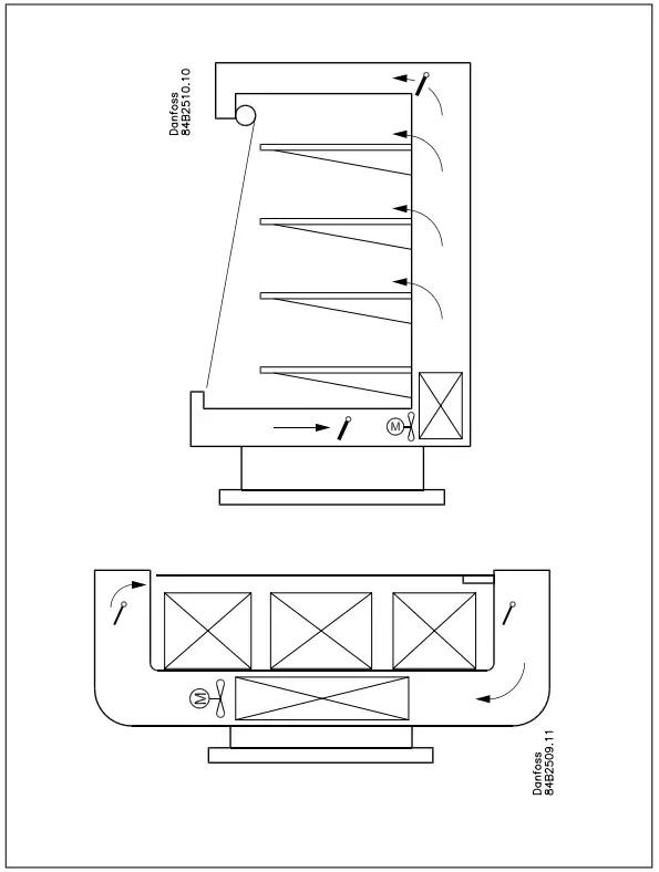
Application
- The controller is used for temperature control of refrigeration appliances and cold rooms in supermarkets
- Control of defrost, fans, alarm and light
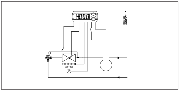
Principle
The controller contains a temperature control where the signal can be received from one temperature sensor. The sensor is placed in the cold air flow after the evaporator or in the warm air flow just before the evaporator. The controller controls the defrost with either natural defrost or electric defrost. Renewed cutting after defrost can be accomplished based on time or temperature. A measurement of the defrost temperature can be obtained directly through the use of a defrost sensor. Two to four relays will cut the required functions in and out – the application determines which:
- Refrigeration (compressor or solenoid valve)
- Defrost
- Fan
- Alarm
- Light
The different applications are described on the next page.
Advantages
- Integrated refrigeration-technical functions
- Defrost on demand in 1:1 systems
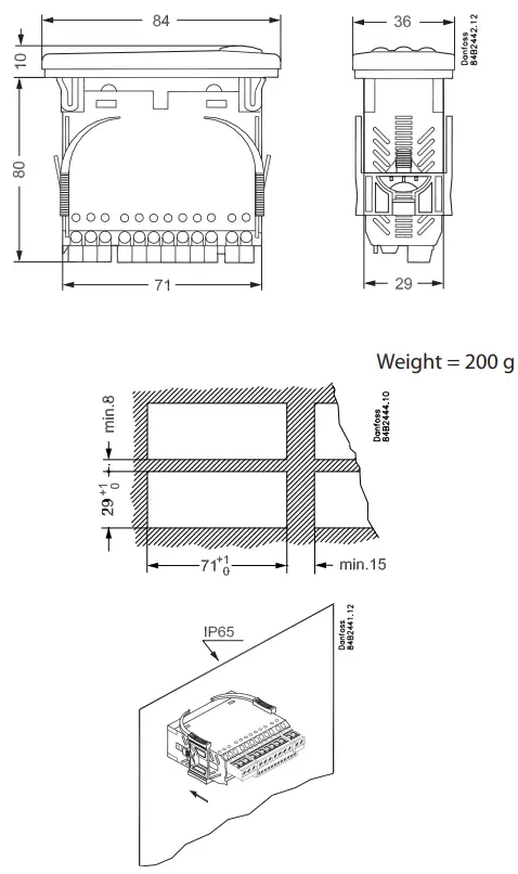
- Buttons and seal are embedded in the front
- IP65 enclosure on the front panel
- Digital input for either:
- Door contact function with alarm
- Defrost start
- Start/stop of regulation
- Night operation
- Changeover between two temperature references
- Case cleaning function
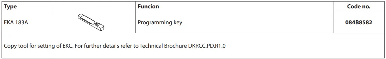
- Instant programming via programming key
- HACCP Factory calibration that will guarantee better measurement accuracy than stated in the standard EN ISO 23953-2 without subsequent calibration (Pt 1000 ohm sensor)
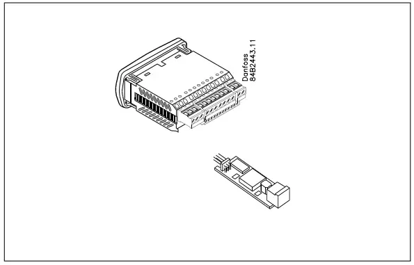
Extra module
- The controller can afterwards be fitted with an insertion module if the application requires it. The controller has been prepared with plug, so the module simply has to be pushed in.
EKC 202A
Controller with two relay outputs, two temperature sensors, and a digital input. Temperature control at the start/stop of the compressor/solenoid valve
Defrost sensor
Electrical defrost / gas defrost
Alarm function
If an alarm function is required, relay number two may be used for it. Defrost is performed here with a circulation of the air as the fans are operating continuously.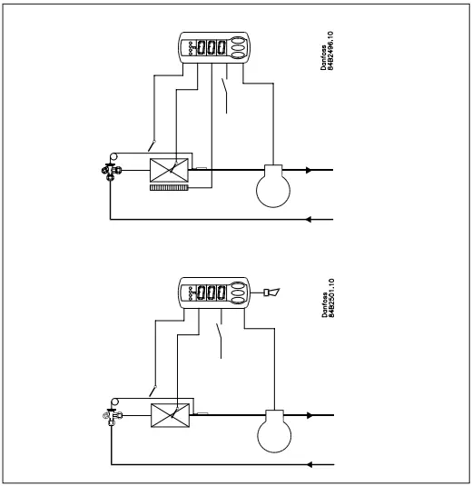
EKC 202B
Controller with three relay outputs, two temperature sensors, and a digital input. Temperature control at start/stop of compressor/solenoid valve, Defrost sensor, Electrical defrost / gas defrost Relay output 3 is used for control of fan.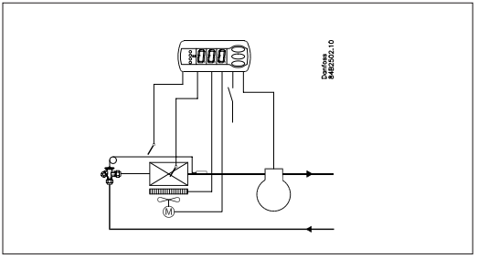
EKC 202C
Controller with four relay outputs, two temperature sensors, and a digital input. Temperature control at start/stop of compressor/solenoid valve, Defrost sens, or Electrical defrost / gas defrost. Control of fan Relay output 4 can be used for an alarm function or for a light function.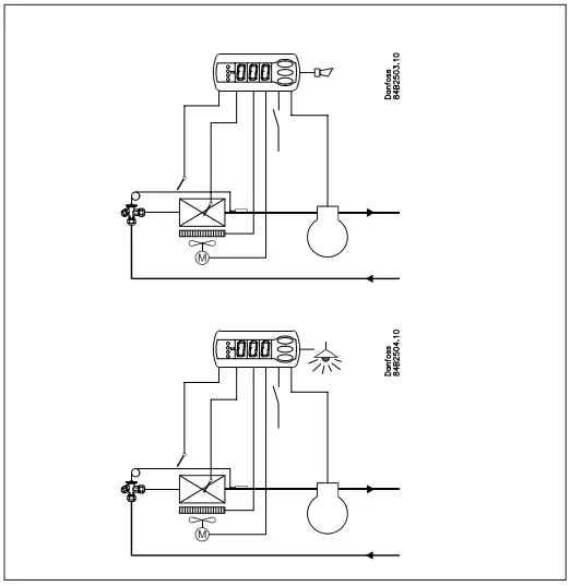
Start of defrost
A defrost can be started in different ways
Interval: Defrost is started at fixed time intervals, say, every eight hours
- Refrigeration time: Defrost is started at fixed refrigeration time intervals. In other words, a low need for refrigeration will ”postpone” the coming defrost
- Contact Defrost is started here with a pulse signal on a digital input.
- Manual: An extra defrost can be activated from the controller’s lowest button
- S5-temp. In 1:1 systems, the efficiency of the evaporator can be followed. Icing up will start a defrost.
- Schedule Defrost here can be started at fixed times of the day and night. But max. six defrosts
- Network A defrost can be started via data communication
All the mentioned methods can be used at random – if just one of them is activated, a defrost will be started. When the defrost starts, the defrost timers are set at zero.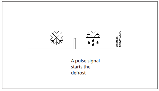
If you need coordinated defrost, this must be done via data communication.
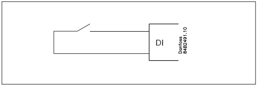
Digital input
The digital input can be used for the following functions:
- Door contact function with alarm if the door has been open for too long.
- Defrost start
- Start/stop of regulation
- Change-over to night operation
- Case cleaning
- Change to another temperature reference
- Inject on/off
Case cleaning function
This function makes it easy to steer the refrigeration appliance through a cleaning phase. Via three pushes on a switch, you change from one phase to the next phase. The first push stops the refrigeration – the fans keep working.”Later”: The next push stops the fans.”Still later,”: The next push restarts refrigeration The different situations can be followed on the display. There is no temperature monitoring during case cleaning. On the network, a cleaning alarm is transmitted to the system unit. This alarm can be ”logged” so that proof of the sequence of events is provided.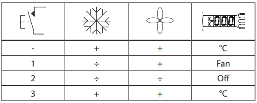
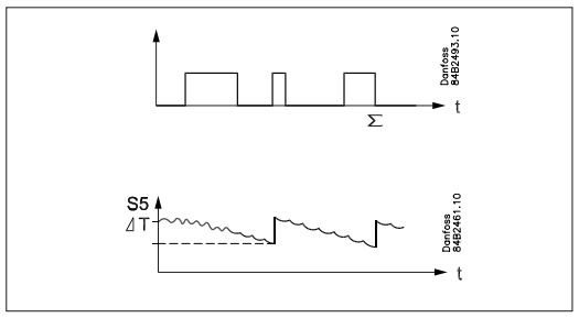
Defrost on demand
- Based on refrigeration time, when the aggregate refrigeration time has passed a fixed time, a defrost will be started.
- Based on temperature, the controller will constantly follow the temperature at S5. Between two defrosts, the S5 temperature will become lower the more the evaporator ices up (the compressor operates for a longer time and pulls the S5 temperature further down). When the temperature passes a set allowed variation, the defrost will be started.
This function can only be used in 1:1 systems
Operation
Display
The values will be shown with three digits, and with a setting you can determine whether the temperature are to be shown in °C or in °F.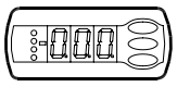
Light-emitting diodes (LED) on the front panel
There are leds on the front panel which will light up when the belonging relay is activated.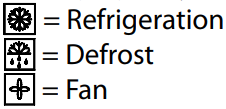
The light-emitting diodes will flash when there is an alarm. In this situation, you can download the error code to the display and cancel/sign for the alarm by giving the top button a brief push.
Defrost
During defrost a–d– is shown in the display. This view will continue up to 15 min. after the cooling has resumed. However, the view of –d– will be discontinued if:
- The temperature is suitable within the 15 minutes
- The regulation is stopped with the “Main Switch”
- A high temperature alarm appears
The buttons
When you want to change a setting, the upper and lower buttons will give you a higher or lower value, depending on the button you are pushing. But before you change the value, you must have access to the menu. You obtain this by pushing the upper button for a couple of seconds – you will then enter the column with parameter codes. Find the parameter code you want to change and push the middle buttons until the value for the parameter is shown. When you have changed the value, save the new value by once more pushing the middle button.
Examples
Set menu
- Push the upper button until a parameter r01 is shown
- Push the upper or the lower button and find the parameter you want to change
- Push the middle button until the parameter value is shown
- Push the upper or the lower button and select the new value
- Push the middle button again to enter the value. Cutout alar,m relay / receipt alarm/see alarm code
- Push briefly the upper button
- If there are several alarm codes, they are found in a rolling stack. Push the uppermost or lowermost button to scan the rolling stack.
Set temperature
- Push the middle button until the temperature value is shown
- Push the upper or the lower button and select the new value
- Push the middle button to select the setting
Manuel starts or stop the defrost
- Push the lower button for four seconds. See the temperature at the defrost sensor
- Push briefly the lower button. If no sensor has been mounted, ”non” will appear.
100% tight
The buttons and the seal are imbedded in the front. A special moulding technique unites the hard front plastic, the softer buttons and the seal, so that they become an integral part of the front panel. There are no openings that can receive moisture or dirt.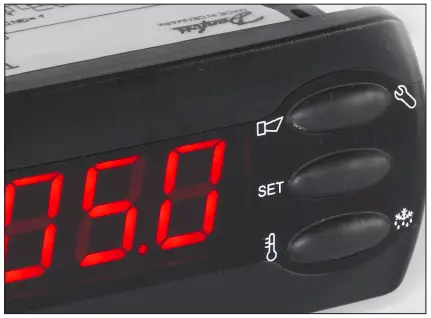
| Parameters | Controller | Min.- value | Max.- value | Factory setting | Actual setting | |||
| Function | Codes | EKC
202A |
EKC
202B |
EKC
202C |
||||
| Normal operation | ||||||||
| Temperature (set point) | — | -50°C | 50°C | 2°C | ||||
| Thermostat | ||||||||
| Differential | r01 | 0,1 K | 20 K | 2 K | ||||
| Max. limitation of set point setting | r02 | -49°C | 50°C | 50°C | ||||
| Min. limitation of set point setting | r03 | -50°C | 49°C | -50°C | ||||
| Adjustment of temperature indication | r04 | -20 K | 20 K | 0.0 K | ||||
| Temperature unit (°C/°F) | r05 | °C | °F | °C | ||||
| Correction of the signal from Sair | r09 | -10 K | 10 K | 0 K | ||||
| Manual service(-1), stop regulation(0), start regulation (1) | r12 | -1 | 1 | 1 | ||||
| Displacement of reference during night operation | r13 | -10 K | 10 K | 0 K | ||||
| Activation of reference displacement r40 | r39 | OFF | on | OFF | ||||
| Value of reference displacement (activation by r39 or DI) | r40 | -50 K | 50 K | 0 K | ||||
| Alarm | ||||||||
| Delay for temperature alarm | A03 | 0 min | 240 min | 30 min | ||||
| Delay for door alarm | A04 | 0 min | 240 min | 60 min | ||||
| Delay for temperature alarm after defrost | A12 | 0 min | 240 min | 90 min | ||||
| High alarm limit | A13 | -50°C | 50°C | 8°C | ||||
| Low alarm limit | A14 | -50°C | 50°C | -30°C | ||||
| Alarm delay DI1 | A27 | 0 min | 240 min | 30 min | ||||
| High alarm limit for condenser temperature (o70) | A37 | 0°C | 99°C | 50°C | ||||
| Compressor | ||||||||
| Min. ON-time | c01 | 0 min | 30 min | 0 min | ||||
| Min. OFF-time | c02 | 0 min | 30 min | 0 min | ||||
| Compressor relay must cutin and out inversely (NC-function) | c30 | 0 / OFF | 1 / on | 0 / OFF | ||||
| Defrost | ||||||||
| Defrost method (none/EL/gas) | d01 | no | gas | EL | ||||
| Defrost stop temperature | d02 | 0°C | 25°C | 6°C | ||||
| Interval between defrost starts | d03 | 0 hours | 48 hours | 8 hours | ||||
| Max. defrost duration | d04 | 0 min | 180 min | 45 min | ||||
| Displacement of time on cutin of defrost at start-up | d05 | 0 min | 240 min | 0 min | ||||
| Drip off time | d06 | 0 min | 60 min | 0 min | ||||
| Delay for fan start after defrost | d07 | 0 min | 60 min | 0 min | ||||
| Fan start temperature | d08 | -15°C | 0°C | -5°C | ||||
| Fan cutin during defrost
0: Stopped 1: Running during the whole phase 2: Running during the heating phase only |
d09 | 0 | 2 | 1 | ||||
| Defrost sensor (0=time, 1=S5, 2=Sair) | d10 | 0 | 2 | 0 | ||||
| Max. aggregate refrigeration time between two defrosts | d18 | 0 hours | 48 hours | 0 hours | ||||
| Defrost on demand – S5 temperature’s permitted variation during frost build-up. On
central plant choose 20 K (=off) |
d19 | 0 K | 20 K | 20 K | ||||
| Fans | ||||||||
| Fan stop at cutout compressor | F01 | no | yes | no | ||||
| Delay of fan stop | F02 | 0 min | 30 min | 0 min | ||||
| Fan stop temperature (S5) | F04 | -50°C | 50°C | 50°C | ||||
| Real time clock | ||||||||
| Six start times for defrost. Setting of hours.
0=OFF |
t01-t06 | 0 hours | 23 hours | 0 hours | ||||
| Six start times for defrost. Setting of minutes.
0=OFF |
t11-t16 | 0 min | 59 min | 0 min | ||||
| Clock – Setting of hours | t07 | 0 hours | 23 hours | 0 hours | ||||
| Clock – Setting of minute | t08 | 0 min | 59 min | 0 min | ||||
| Clock – Setting of date | t45 | 1 | 31 | 1 | ||||
| Clock – Setting of month | t46 | 1 | 12 | 1 | ||||
| Clock – Setting of year | t47 | 0 | 99 | 0 | ||||
| Miscellaneous | ||||||||
| Delay of output signals after power failure | o01 | 0 s | 600 s | 5 s | ||||
| Input signal on DI1. Function:
0=not used. 1=status on DI1. 2=door function with alarm when open. 3=door alarm when open. 4=defrost start (pulse-signal). 5=ext.main switch. 6=night operation 7=change reference (r40 will be activated) 8=alarm function when closed. 9=alarm func- tion when open. 10=case cleaning (pulse signal). 11=Inject off when open. |
o02 | 0 | 11 | 0 | ||||
| Network address | o03 | 0 | 240 | 0 | ||||
| On/Off switch (Service Pin message) | o04 | OFF | ON | OFF | ||||
| Access code 1 (all settings) | o05 | 0 | 100 | 0 | ||||
| Used sensor type (Pt /PTC/NTC) | o06 | Pt | ntc | Pt | ||||
| Display step = 0.5 (normal 0.1 at Pt sensor) | o15 | no | yes | no | ||||
| Max hold time after coordinated defrost | o16 | 0 min | 60 min | 20 | ||||
| Configuration of light function (relay 4)
1=ON during day operation. 2=ON / OFF via data communication. 3=ON follows the DI- function, when DI is selected to door function or to door alarm |
o38 | 1 | 3 | 1 | ||||
| Activation of light relay (only if o38=2) | o39 | OFF | ON | OFF | ||||
| Case cleaning. 0=no case cleaning. 1=Fans only. 2=All output Off. | o46 | 0 | 2 | 0 | ||||
| Access code 2 (partly access) | o64 | 0 | 100 | 0 | ||||
| Save the controllers present settings to the programming key. Select your own number. | o65 | 0 | 25 | 0 | ||||
| Load a set of settings from the programming key (previously saved via o65 function) | o66 | 0 | 25 | 0 | ||||
| Replace the controllers factory settings with the present settings | o67 | OFF | On | OFF | ||||
| Re alternative application for the S5 sensor (maintain the setting at 0 if it is used as defrost sensor, otherwise 1 = product sensor and 2 = condenser sensor with alarm) | o70 | 0 | 2 | 0 | ||||
| Select application for relay 4: 1=defrost/light, 2= alarm | o72 | defrost /
Alarm |
Light /
Alarm |
1 | 2 | 2 | ||
| Service | ||||||||
| Temperature measured with S5 sensor | u09 | |||||||
| Status on DI1 input. on/1=closed | u10 | |||||||
| Status on night operation (on or off) 1=closed | u13 | |||||||
| Read the present regulation reference | u28 | |||||||
| Status on relay for cooling (Can be controlled manually, but only when r12=-1) | u58 | |||||||
| Status on relay for fans (Can be controlled manually, but only when r12=-1) | u59 | |||||||
| Status on relay for defrost. (Can be controlled manually, but only when r12=-1) | u60 | |||||||
| Temperature measured with Sair sensor | u69 | |||||||
| Status on relay 4 (alarm, defrost, light). (Can be controlled manually, but only when
r12=-1) |
u71 | |||||||
Factory setting
If you need to return to the factory-set values, it can be done in this way:
- Cut out the supply voltage to the controller
- Keep the upper and lower buttons depressed at the same time as you reconnect the supply voltage.
| Fault code display | Alarm code display | Status code display | |||
| E1 | Fault in controller | A 1 | High temperature alarm | S0 | Regulating |
| E6 | Change battery + check clock | A 2 | Low temperature alarm | S1 | Waiting for end of the coordinated defrost |
| E 27 | S5 sensor error | A 4 | Door alarm | S2 | ON-time Compressor |
| E 29 | Sair sensor error | A 5 | Max. Hold time | S3 | OFF-time Compressor |
| A 15 | DI 1 alarm | S4 | Drip-off time | ||
| A 45 | Standby mode | S10 | Refrigeration stopped by main switch | ||
| A 59 | Case cleaning | S11 | Refrigeration stopped by a thermostat | ||
| A 61 | Condenser alarm | S14 | Defrost sequence. Defrosting | ||
| S15 | Defrost sequence. Fan delay | ||||
| S16 | Refrigeration stopped because of open DI
input |
||||
| S17 | Door open (open DI input) | ||||
| S20 | Emergency cooling | ||||
| S25 | Manual control of outputs | ||||
| S29 | Case cleaning | ||||
| S32 | Delay of output at start-up | ||||
| non | The defrost temperature cannot be dis-
played. There is stop based on time |
||||
| -d- | Defrost in progress / First cooling after
defrost |
||||
| PS | Password required. Set password | ||||
Start-up:
Regulation starts when the voltage is on.
- Go through the survey of factory settings. Make any necessary changes in the respective parameters.
- For the network. Set the address in o03 and then transmit it to the gateway/ system unit with setting o04.
Functions
Here is a description of the individual functions. A controller only contains this part of the functions. Cf. the menu survey.
| Function | Para- meter | Parameter by operation via data com- munication |
| Normal display | ||
| Normally the temperature value from thermostat sensor Sair is displayed. | Display air (u69) | |
| Thermostat | Thermostat control | |
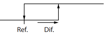
| Set point
Regulation is based on the set value plus a displacement, if applicable. The value is set via a push on the centre button. The set value can be locked or limited to a range with the settings in r02 and r03. The reference at any time can be seen in ”u28 Temp. ref” |
Cutout °C | |
| Differential
When the temperature is higher than the reference + the set differential, the compressor relay will be cut in. It will cut out again when the temperature comes down to the set reference. |
r01 | Differential |
| Set point limitation
The controller’s setting range for the set point may be narrowed down, so that much too high or much too low values are not set accidentally – with resulting damages. |
||
| To avoid a too high setting of the set point, the max. allowable reference value must be lowered. | r02 | Max cutout °C |
| To avoid a too low setting of the set point, the min. allowable reference value must be increased. | r03 | Min cutout °C |
| Correction of the display’s temperature showing
If the temperature at the products and the temperature received by the controller are not identical, an offset adjustment of the shown display temperature can be carried out. |
r04 | Disp. Adj. K |
| Temperature unit
Set here if the controller is to show temperature values in °C or in °F. |
r05 | Temp. unit
°C=0. / °F=1 (Only °C on AKM, whatever the setting) |
| Correction of signal from Sair
Compensation possibility through long sensor cable |
r09 | Adjust Sair |
| Start / stop of refrigeration
With this setting refrigeration can be started, stopped or a manual override of the outputs can be allowed. Start / stop of refrigeration can also be accomplished with the external switch function con- nected to the DI input. Stopped refrigeration will give a ”Standby alarm”. |
r12 | Main Switch
1: Start 0: Stop -1: Manual control of outputs allowed |
| Night setback value
The thermostat’s reference will be the set point plus this value when the controller changes over to night operation. (Select a negative value if there is to be cold accumulation.) |
r13 | Night offset |
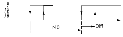
| Activation of reference displacement
When the function is changed to ON the thermostat differential will be increased by the value in r40. Activation can also take place via input DI (defined in o02).
|
r39 | Th. offset |
| Value of reference displacement
The thermostat reference and the alarm values are shifted by the following number of degrees when the displacement is activated. Activation can take place via r39 or input DI |
r40 | Th. offset K |
| Night setback
(start of night signal) |
| Alarm | Alarm settings | |
| The controller can give alarm in different situations. When there is an alarm all the light-emitting diodes (LED) will flash on the controller front panel, and the alarm relay will cut in. | With data communication, the importance of individual alarms can be defined. Setting is carried out in the “Alarm destinations” menu. | |
| Alarm delay (short alarm delay)
If one of the two limit values is exceeded, a timer function will commence. The alarm will not become active until the set time delay has passed. The time delay is set in minutes. |
A03 | Alarm delay |
| Time delay for the door alarm
The time delay is set in minutes. The function is defined in o02. |
A04 | DoorOpen del |
| Time delay for cooling (long alarm delay)
This time delay is used during start-up, during defrost, and immediately after a defrost. There will be change-over to the normal time delay (A03) when the temperature has dropped below the set upper alarm limit. The time delay is set in minutes. |
A12 | Pulldown del |
| Upper alarm limit
Here you set when the alarm for high temperature is to start. The limit value is set in °C (absolute value). The limit value will be raised during night operation. The value is the same as the one set for night setback, but will only be raised if the value is positive. The limit value will also be raised in connection with reference displacement r39. |
A13 | HighLim Air |
| Lower alarm limit
Here you set when the alarm for low temperature is to start. The limit value is set in °C (absolute value). The limit value will also be raised in connection with reference displacement r39. |
A14 | LowLim Air |
| Delay of a DI alarm
A cut-out/cut-in input will result in alarm when the time delay is passed. The function is defined in o02. |
A27 | AI.Delay DI |
| High alarm limit for condenser temperature
If the S5 sensor is used for monitoring the condenser’s temperature you must set the value at which the alarm is to become activated. The value is set in °C. The definition of S5 as a condenser sensor is accomplished in o70. The alarm is reset again to 10 K below the set temperature. |
A37 | Condtemp Al. |
| Reset alarm |
| Compressor | Compressor control | |
| The compressor relay works in conjunction with the thermostat. When the thermostat calls for refrigeration will the compressor relay be operated. | ||
| Running times
To prevent irregular operation, values can be set for the time the compressor is to run once it has been started. And for how long it at least to be stopped? The running times are not observed when defrosts start. |
||
| Min. ON-time (in minutes) | c01 | Min. On time |
| Min. OFF-time (in minutes) | c02 | Min. Off time |
| Reversed relay function for the compressor relay
0: Normal function where the relay cuts in when refrigeration is demanded 1: Reversed function where the relay cuts out when refrigeration is demanded (this wiring pro- duces the result that there will be refrigeration if the supply voltage to the controller fails). |
c30 | Cmp relay NC |
| Defrost | Defrost control | |
| The controller contains a timer function that is zeroset after each defrost start. The timer function will start a defrost if/when the interval time is passed.
The timer function starts when voltage is connected to the controller, but it is displaced the first time by the setting in d05. If there is power failure, the timer value will be saved and continue from here when the power returns. This timer function can be used as a simple way of starting defrosts, but it will always act as a safety defrost if one of the subsequent defrost starts is not received. The controller also contains a real-time clock. By means of the settings of this clock and times for the required defrost times, defrost can be started at fixed times of the day. If there is a risk of power failure for periods longer than four hours, a battery module should be mounted in the controller. Defrost start can also be accomplished via data communication, via contact signals or manually start-up. |
||
| All starting methods will function in the controller. The different functions have to be set, so that defrosts do not ”come tumbling” one after the other.
Defrost can be accomplished with electricity, hot gas or brine. The actual defrost will be stopped based on time or temperature with a signal from a temperature sensor. |
||
| Defrost method
Here you set whether defrost is to be accomplished with electricity or “non”. During defrost the defrost relay will be cut in. When gas defrosting the compressor relay will be cut in during defrost. |
d01 | Def. method |
| Defrost stop temperature
The defrost is stopped at a given temperature which is measured with a sensor (the sensor is defined in d10). The temperature value is set. |
d02 | Def. Stop Temp |
| Interval between defrost starts
The function is zeroset and will start the timer function at each defrost start. When the time has expired the function will start a defrost. The function is used as a simple defrost start, or it may be used as a safeguard if the normal signal fails to appear. If master/slave defrost without clock function or without data communication is used, the interval time will be used as max. time between defrosts. If a defrost start via data communication does not take place, the interval time will be used as max. time between defrosts. When there is defrost with clock function or data communication, the interval time must be set for a somewhat longer period of time than the planned one, as the interval time will otherwise start a defrost which a little later will be followed by the planned one. In connection with a power failure, the interval time will be maintained, and when the power returns the interval time will continue from the maintained value. The interval time is not active when set to 0. |
d03 | Def Interval (0=off) |
| Max defrost duration
This setting is a safety time so that the defrost will be stopped if there has not already been a stop based on temperature or via coordinated defrost. (The setting will be the defrost time if d10 is selected to be 0) |
d04 | Max Def. time |
| Time staggering for defrost cut-ins during start-up
The function is only relevant if you have several refrigeration appliances or groups where you want the defrost to be staggered in relation to one another. The function is furthermore only relevant if you have chosen defrost with interval start (d03). The function delays the interval time d03 by the set number of minutes, but it only does it once, and this at the very first defrost taking place when voltage is connected to the controller. The function will be active after each and every power failure. |
d05 | Time Stagg. |
| Drip-off time
Here you set the time that is to elapse from a defrost and until the compressor is to start again. (The time when water drips off the evaporator). |
d06 | DripOff time |
| Delay of fan start after defrost
Here you set the time that is to elapse from compressor start after a defrost and until the fan may start again. (The time when water is “tied” to the evaporator). |
d07 | FanStartDel |
| Fan start temperature
The fan may also be started a little earlier than mentioned under “Delay of fan start after defrost”, if the defrost sensor S5 registers a lower value than the one set here. |
d08 | FanStartTemp |
| Fan cut in during defrost
Here you can set whether the fan is to operate during defrost. 0: Stopped (Runs during pump down) 1: Running during the whole phase 2: Running during the heating phase only. After that stopped |
d09 | FanDuringDef |
| Defrost sensor
Here you define the defrost sensor. 0: None, defrost is based on time 1: S5 2: Sair |
d10 | DefStopSens. |
| Defrost on demand – aggregate refrigeration time
Set here is the refrigeration time allowed without defrosts. If the time is passed, a defrost will be started. With setting = 0 the function is cut out. |
d18 | MaxTherRunT |
| Defrost on demand – S5 temperature
The controller will follow the effectivity of the evaporator, and via internal calculations and measurements of the S5 temperature it will be able to start a defrost when the variation of the S5 temperature becomes larger than required. Here you set how large a slide of the S5 temperature can be allowed. When the value is passed, a defrost will start. The function can only be used in 1:1 systems when the evaporating temperature will become lower to ensure that the air temperature will be maintained. In central systems the function must be cut out. With setting = 20 the function is cut out |
d19 | CutoutS5Dif. |
| If you wish to see the temperature at the S5 sensor, push the controller’s lowermost button. | Defrost temp. | |
| If you wish to start an extra defrost, push the controller’s lowermost button for four seconds. You can stop an ongoing defrost in the same way | Def Start
Here you can start a manual defrost. |
|
| Hold After Def
Shows ON when the controller is operating with coordinated defrost. |
||
| Defrost State Status on defrost
1= pump down / defrost |
||
| Fan | Fan control | |
| The fan stopped at the cut-out compressor
Here you can select whether the fan is to be stopped when the compressor is cut out |
F01 | Fan stop CO
(Yes = Fan stopped) |
| Delay of fan stop when the compressor is cut out
If you have chosen to stop the fan when the compressor is cut out, you can delay the fan stop when the compressor has stopped. Here you can set the time delay. |
F02 | Fan del. CO |
| Fan stop temperature
The function stops the fans in an error situation, so that they will not provide power to the appli- ance. If the defrost sensor registers a higher temperature than the one set here, the fans will be stopped. There will be re-start at 2 K below the setting. The function is not active during a defrost or start-up after a defrost. With setting +50°C the function is interrupted. |
F04 | FanStopTemp. |
| Internal defrosting schedule/clock function | ||
| (Not used if an external defrosting schedule is used via data communication.) Up to six individual times can be set for the defrost start throughout the day. | ||
| Defrost start, hour setting | t01-t06 | |
| Defrost start, minute setting (1 and 11 belong together, etc.) When all t01 to t16 equal 0, the clock will not start defrosting. | t11-t16 | |
| Real-time clock
Setting the clock is only necessary when there is no data communication. In the event of a power failure of less than four hours, the clock function will be saved. When mounting a battery module the clock function can preserved longer. (EKC 202 only) |
||
| Clock: Hour setting | t07 | |
| Clock: Minute setting | t08 | |
| Clock: Date setting | t45 | |
| Clock: Month setting | t46 | |
| Clock: Year setting | t47 |
| Miscellaneous | Miscellaneous | |
| Delay of the output signal after start-up
After start-up or a power failure, the controller’s functions can be delayed so that overloading of the electricity supply network is avoided. Here you can set the time delay. |
o01 | DelayOfOutp. |
| Digital input signal – DI
The controller has a digital input which can be used for one of the following functions: Off: The input is not used 1) Status display of a contact function 2) Door function. When the input is open it signals that the door is open. The refrigeration and the fans are stopped. When the time setting in “A04” is passed, an alarm will be given and refrigeration will be resumed. 3) Door alarm. When the input is open it signals that the door is open. When the time setting in “A04” is passed, there will be alarm. 4) Defrost. The function is started with a pulse signal. The controller will register when the DI input is activated. The controller will then start a defrost cycle. If the signal is to be received by several controllers it is important that ALL connections are mounted the same way (DI to DI and GND to GND). 5) Main switch. Regulation is carried out when the input is short-circuited, and regulation is stopped when the input is put in place. OFF. 6) Night operation. When the input is short-circuited, there will be a regulation for night operation. 7) Reference displacement when DI1 is short-circuited. Displacement with “r40”. 8) Separate alarm function. An alarm will be given when the input is short-circuited. 9) Separate alarm function. An alarm will be given when the input is opened. (For 8 and 9 the time delay is set in A27) 10) Case cleaning. The function is started with a pulse signal. Cf. also description on page 4. 11) Inject on/off. Off when DI is open. |
o02 | DI 1 Config.
Definition takes place with the numerical value shown to the left. (0 = off)
DI state (Measurement) The DI input’s present status is shown here. ON or OFF. |
| Address
If the controller is built into a network with data communication, it must have an address, and the master gateway of the data communication must then know this address. The installation of the data communication cable has been mentioned in a separate document, “RC8AC”. The address is set between 1 and 240, gateway determined The address is sent to the system manager when the menu o04 is set to ‘ON’, or when the system manager’s scanning function is activated. (o04 is only to be used if the data communication is LON.) |
After installation of data communication, the controller can be operated on an equal footing with the other controllers in ADAP- KOOL® refrigeration controls. | |
| o03 | ||
| o04 | ||
| Access code 1 (Access to all settings)
If the settings in the controller are to be protected with an access code you can set a numerical value between 0 and 100. If not, you can cancel the function with setting 0. (99 will always give you access). |
o05 | – |
| Sensor type
Normally, a Pt 1000 sensor with great signal accuracy is used. But you can also use a sensor with another signal accuracy. That may either be a PTC 1000 sensor or an NTC sensor (5000 Ohm at 25°C). All the mounted sensors must be of the same type. |
o06 | SensorConfig Pt = 0
PTC = 1 NTC = 2 |
| Display step
Yes: Gives steps of 0.5° No: Gives steps of 0.1° |
o15 | Disp. Step = 0.5 |
| Max. standby time after coordinated defrost
When a controller has completed a defrost, it will wait for a signal that tells the refrigeration may be resumed. If this signal fails to appear for one reason or another, the controller will itself starts the refrigeration when this standby time has elapsed. |
o16 | Max HoldTime |
| Configuration of light function
1) The relay cuts in during day operation 2) The relay to be controlled via data communication 3) The relay to be controlled by the door switch defined in either o02 where the setting is selected to either 2 or 3. When the door is opened the relay will cut in. When the door is closed again there will be a time delay of two minutes before the light is switched off. |
o38 | Light config |
| Activation of light relay
The light relay can be activated here (if 038=2) |
o39 | Light remote |
| Case cleaning
The status of the function can be followed here or the function can be started manually. 0 = Normal operation (no cleaning) 1 = Cleaning with fans operating. All other outputs are Off. 2 = Cleaning with stopped fans. All outputs are Off. If the function is controlled by a signal at the DI input, the relevant status can be seen here in the menu. |
o46 | Case clean |
| Access code 2 (Access to adjustments)
There is access to adjustments of values, but not to configuration settings. If the settings in the controller are to be protected with an access code you can set a numerical value between 0 and 100. If not, you can cancel the function with setting 0. If the function is used, access code 1 (o05) must also be used. |
o64 | – |
| Copy the controller’s present settings
With this function, the controller’s settings can be transferred to a programming key. The key can contain up to 25 different sets. Select a number. All settings except for Address (o03) will be copied. When copying has started, the display returns to o65. After two seconds, you can move into the menu again and check whether the copying was satisfactory. Showing of a negative figure spells problems. See the significance in the Fault Message section. |
o65 | – |
| Copy from the programming key
This function downloads a set of settings previously saved in the controller. Select the relevant number. All settings except for Address (o03) will be copied. When copying has started the display returns to o66. After two seconds, you can move back into the menu again and check whether the copying was satisfactory. Showing of a negative figure spells problems. See the significance in the Fault Message section. |
o66 | – |
| Save as factory setting
With this setting you save the controller’s actual settings as a new basic setting (the earlier fac- tory settings are overwritten). |
o67 | – |
| Other application for S5 sensor
Maintain the setting at 0 if the sensor has been defined as defrost sensor in D10. If D10 has been set at 0 or 2 the S5 input can be used as product sensor or condenser sensor. Here you define which: 0: Defrost sensor 1: Product sensor 2: Condenser sensor with alarm |
o70 | S5 Config |
| Relay 4
Here you define the application for relay 4: 1: Defrost (EKC 202A) or Light (EKC 202C) 2: Alarm |
o72 | DO4 Config |
| – – – Night Setback 0=Day
1=Night |
| Service | Service | |
| Temperature measured with S5 sensor | u09 | S5 temp. |
| Status on DI input. on/1=closed | u10 | DI1 status |
| Status on night operation (on or off) 1=night operation | u13 | Night Cond. |
| Read the present regulation reference | u28 | Temp. ref. |
| * Status on relay for cooling | u58 | Comp1/LLSV |
| * Status on relay for fan | u59 | Fan relay |
| * Status on relay for defrost | u60 | Def. relay |
| * Temperature measured with Sair sensor | u69 | Sair temp |
| * Status on relay 4 (alarm, defrost or light function) | u71 | DO4 status |
| *) Not all items will be shown. Only the function belonging to the selected application can be seen. |
| Fault message | Alarms | |
| In an error situation the LED’s on the front will flash and the alarm relay will be activated. If you push the top button in this situation you can see the alarm report in the display. If there are further push again to see them.
There are two kinds of error reports – it can either be an alarm occurring during the daily opera- tion, or there may be a defect in the installation. A-alarms will not become visible until the set time delay has expired. E-alarms, on the other hand, will become visible the moment the error occurs. (An A alarm will not be visible as long as there is an active E alarm). Here are the messages that may appear: |
1 = alarm |
|
| A1: High temperature alarm | High t. alarm | |
| A2: Low temperature alarm | Low t. alarm | |
| A4: Door alarm | Door Alarm | |
| A5: Information. Parameter o16 is expired | Max Hold Time | |
| A15: Alarm. Signal from DI input | DI1 alarm | |
| A45: Standby position (stopped refrigeration via r12 or DI input) | Standby mode | |
| A59: Case cleaning. Signal from DI input | Case cleaning | |
| A61: Condenser alarm | Cond. alarm | |
| E1: Faults in the controller | EKC error | |
| E6: Fault in real-time clock. Check the battery / reset the clock. | – | |
| E27: Sensor error on S5 | S5 error | |
| E29: Sensor error on Sair | Sair error | |
| When copying settings to or from a copying key with functions o65 or o66, the following infor- mation may appear:
0: Copying concluded and OK 4: Copying key not correctly mounted 5: Copying was not correct. Repeat copying 6: Copying to EKC incorrect. Repeat copying 7: Copying to copying key incorrect. Repeat copying 8: Copying not possible. Order number or SW version do not match 9: Communication error and timeout 10: Copying still going on (The information can be found in o65 or o66 a couple of seconds after copying has been started). |
||
| Alarm destinations | ||
| The importance of the individual alarms can be defined with a setting (0, 1, 2 or 3) |
Warning! Direct start of compressors
To prevent compressor breakdown parameters c01 and c02 should be set according to the supplier’s requirements o,r in general, Hermetic Compressors c02 min. 5 minutes, Semihermetic Compressors c02 min. 8 minutes, and c01 min. 2 to 5 minutes ( Motor from 5 to 15 KW ) * ). Direct activation of solenoid valves does not require settings different from factory (0).
Override
The controller contains a number of functions that can be used together with the override function in the master gateway / System Manager.
|
Function via data communication |
Functions to be used in the gateway’s override function |
Used parameter in EKC 202 |
| Start of defrosting | Defrost control Time schedule | – – – Def. start |
| Coordinated defrost | Defrost control |
– – – HoldAfterDef u60 Def.relay |
| Night setback |
Day/night control Time schedule |
– – – Night setbck |
| Light control | Day/night control Time schedule | o39 Light Remote |
Connections
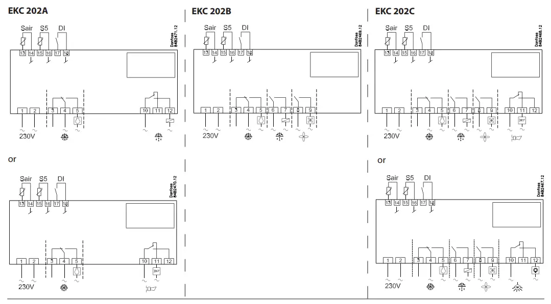
Power supply
- 230 V a.c.
Sensors
- Sair is a thermostat sensor.
- S5 is a defrost sensor and is used if defrost has to be stopped based on temperature. It may, however, also be used as a product sensor or condenser sensor.
Digital On/Off signal
A cut-in input will activate a function. The possible functions are described in menu o02.
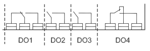
Relays
The general connections are: Refrigeration. The contact will cut in when the controller demands refrigeration Defrost. Fan.
- Alarm. The relay is cut out during normal operation and cuts in in alarm situations and when the controller is dead (de-energised)
- Light. The contact will cut in when the controller demands light.
Electric noise
Cables for sensors, DI inputs, and data communication must be kept separate from other electrical cables:
- Use separate cable trays
- Keep a distance between cables of at least 10 cm
- Long cables at the DI input should be avoided
Data communication
If data communication is used, it is important that the installation of the data communication cable is performed correctly. See the separate literature No. RC8AC.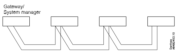
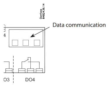
- MODBUS or LON-RS485 via insert cards.
Ordering
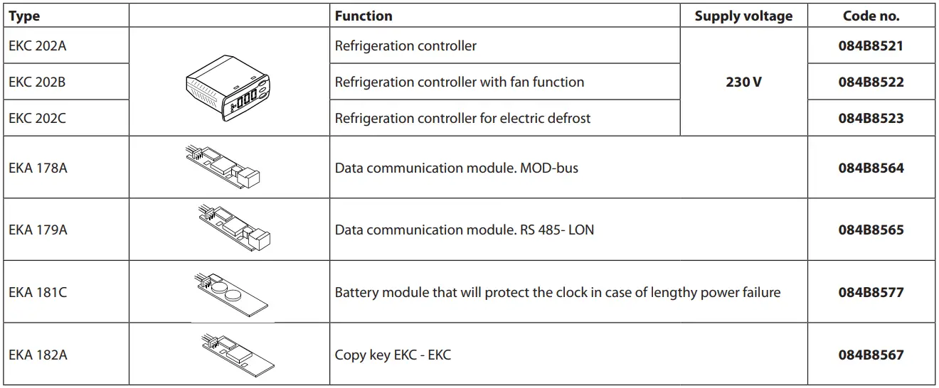
- Temperature sensors: please refer to lit. no. RK0YG
Technical data
| Supply voltage | 230 V a.c. +10/-15 %. 2.5 VA, 50/60 Hz | ||
| Sensors 3 pcs off either | Pt 1000 or
PTC 1000 or NTC-M2020 (5000 ohm / 25°C) |
||
|
Accuracy |
Measuring range | -60 to +99°C | |
|
Controller |
±1 K below -35°C
±0.5 K between -35 to +25°C ±1 K above +25°C |
||
| Pt 1000
sensor |
±0.3 K at 0°C
±0.005 K per grad |
||
| Display | LED, 3-digits | ||
|
Digital inputs |
Signal from contact functions Requirements to contacts: Gold plating, Cable length must be max. 15 m
Use auxiliary relays when the cable is longer |
||
| Electrical connection cable | Max.1,5 mm2 multi-core cable
Max. 1 mm2 on sensors and DI inputs |
||
|
Relays* |
IEC60730 | ||
| EKC 202
|
DO1 | 8 (6) A & (5 FLA, 30 LRA) | |
| DO2 | 8 (6) A & (5 FLA, 30 LRA) | ||
| DO3 | 6 (3) A & (3 FLA, 18 LRA) | ||
| DO4** | 4 (1) A, Min. 100 mA** | ||
| Data communication | Via insert card | ||
|
Environments |
0 to +55°C, During operations
-40 to +70°C, During transport |
||
| 20 – 80% Rh, not condensed | |||
| No shock influence/vibrations | |||
| Enclosure | IP 65 from the front.
Buttons and packing are embedded in the front. |
||
| Escapement reserve for the clock |
4 hours |
||
|
Approvals |
EU Low Voltage Directive and EMC demands re CE-marking complied with
EKC 202: UL approval acc. UL 60730 LVD tested acc. EN 60730-1 and EN 60730-2-9, A1, A2 EMC tested acc. EN 61000-6-3 and EN 61000-6-2 |
||

- DO1 and DO2 are 16 A relays. The mentioned 8 A can be increased up to 10 A, when the ambient temperature is kept below 50°C. DO3 and DO4 are 8A relays. Above max. The load must be kept.
- Gold plating ensures a good function with small contact loads
Danfoss can accept no responsibility for possible errors in catalogues, brochures, and other printed material. Danfoss reserves the right to alter its products without notice. This also applies to products already on order provided that such alterations can be made without subsequent changes being necessary in specifications already agreed. All trademarks in this material are property of the respective companies. Danfoss and Danfoss logotype are trademarks of Danfoss A/S. All rights reserved.
Frequently Asked Questions
How do I start a defrost cycle?
A defrost cycle can be started in various ways, including interval, refrigeration time, contact signal, manual activation, schedule, or network communication.
What can the digital input be used for?
The digital input can be utilized for functions such as door contact with an alarm notification if the door remains open.
Documents / Resources
 |
Danfoss EKC 202A Controller For Temperature Control [pdf] User Guide 202A, 202B, 202C, EKC 202A Controller For Temperature Control, EKC 202A, Controller For Temperature Control, For Temperature Control, Temperature Control |