ADICOS Sensor Unit & Interface

Abstract
The Advanced Discovery System (ADICOS®) is used for early detection of fires in industrial environments. It is comprised of various, separate detector units. By parameterizing and arranging the detectors appropriately, the system fulfills a predefined detection goal. The ADICOS system ensures reliable early detection of embers and smoldering fires even in adverse environments. The detectors of the HOTSPOT® product series are equipped with thermal imaging sensors and use infrared measurement technology and intelligent signal analysis to detect all types of smoldering fires and open fires, even in the incipient stage. The fast response speed of 100 milliseconds enables the monitoring of conveyor belts or other conveyor systems, e.g. on moving embers. ADICOS HOTSPOT-X0 consists of the sensor unit and the ADICOS HOTSPOT-X0 Interface-X1. The ADICOS HOTSPOT-X0 Sensor Unit is an infrared sensor unit that, in combination with the ADICOS HOTSPOT-X0 Interface enables an optical and spatially resolved fire and heat detection in potentially explosive atmospheres of ATEX zones 0, 1, and 2. The ADICOS HOTSPOT-X0 Interface-X1 is an interface between the ADICOS HOTSPOT-X0 Sensor Unit and the fire control panel within potentially explosive atmospheres of ATEX zones 1, and 2. Additionally, it can be used as a connection and branching box (AAB) within these zones.
About this Manual
Objective
These instructions describe the requirements on installation, wiring, commissioning, and oper- ation of the ADICOS HOTSPOT-X0 Sensor Unit and ADICOS HOTSPOT-X0 Interface-X1. After commissioning it is used as reference work in the case of faults. It is exclusively addressed to knowledgeable specialist personnel (–› Chap. 2, Safety instructions).
Explanation of Symbols
This manual follows a certain structure to make it easy to work with and understand. The fol- lowing designations are used throughout.
Operational objectives
Operational objectives specify the result to be achieved by following the subsequent instruc- tions. Operational objectives are shown in bold print.
Instructions
Instructions are the steps to be taken in order to achieve the previously stated operational objective. Instructions appear like this.
Indicates a single instruction
- First of a series of instructions
- Second of a series of instructions etc.
Intermediate states
When it is possible to describe intermediate states or events resulting from the instruction steps (e.g. screens, internal function steps, etc.), they are shown like this:
- Intermediate state
ADICOS HOTSPOT-X0 Sensor Unit and Interface-X1 – Operating manual
- Article number: 410-2410-020-EN-11
- Release date: 23.05.2024 – Translation –
Manufacturer:
GTE Industrieelektronik GmbH Helmholtzstr. 21, 38-40 41747 Viersen
GERMANY
Support hotline: +49 2162 3703-0
E-Mail: support.adicos@gte.de
2024 GTE Industrieelektronik GmbH – This document and all figures contained may not be copied, changed, or distributed without explicit approval by the manufacturer!Subject to technical changes! ADICOS® and HOTSPOT® are registered trademarks of GTE Industrieelektronik GmbH.
Warnings
The following types of notes are used in this manual:
DANGER!
This combination of symbol and signal words indicates an immediately dangerous situation that could lead to death or severe injuries if it is not avoided.
WARNING!
This combination of symbol and signalwordsd indicates a possibly dangerous situation that could lead to death or severe injuries if it is not avoided.
CAUTION!
This combination of symbol and signal word indicates a possibly dangerous situation which could lead to minor injuries if it is not avoided.
NOTICE!
This combination of symbol and signal word indicates a possibly dangerous situation which could lead to property damage if it is not avoided.
Explosion protection
This information type signals measures that must be implemented for maintaining the Explosion protection.
Tips and recommendations
This type of note provides information that is directly relevant to the further operation of the device.
Abbreviations
This manual uses the following abbreviations.
| Abbr. | Meaning |
| ADICOS | Advanced Discovery System |
| X0 | ATEX zone 0 |
| X1 | ATEX zone 1 |
| LED | Light-emitting diode |
Storing the Manual
Store this manual easily reachable and in the direct vicinity of the detector to enable use as needed.
Safety Instructions
The ADICOS HOTSPOT-X0 Sensor Unit and the HOTSPOT-X0 Interface-X1 ensure operational safety assuming proper installation, commissioning, operation, and maintenance. For this purpose, it is required to completely read, understand, and follow these instructions and the safety information contained.
WARNING!
Personal injury and property damage! Incorrect installation and operating errors can cause death, serious injury, and damage to industrial equipment.
- Read the entire manual and follow the instructions!
Explosion Protection
When using ADICOS detectors in potentially explosive atmospheres, follow the specifications of the ATEX operating directive.
Intended Use
The ADICOS HOTSPOT-X0 Interface-X1 is intended for use with the ADICOS HOTSPOT-X0 Sensor Unit and is designated for the detection of fire scenarios in potentially explosive atmospheres of ATEX zones 0, 1, and 2. It may be exclusively operated within ADICOS systems. In this context, the operating parameters described in Chap. 10, »Technical Data« must be met. Compliance with this manual as well as all applicable country-specific provisions is also part of the intended use.
Standards and Regulations
The safety and accident prevention regulations applicable for the specific application must be observed during the ADICOS HOTSPOT-X0 Sensor Unit and HOTSPOT-X0 Interface-X1 installation, commissioning, maintenance, and test.
The ADICOS HOTSPOT-X0 Sensor Unit and HOTSPOT-X0 Interface-X1 also meet the following standards and directives in their current version:
| Standards and Regulations | Description |
| EN 60079-0 | Explosive atmospheres –
Part 0: Equipment – General requirements |
| EN 60079-1 | Explosive atmospheres –
Part 1: Equipment protection by flameproof enclosures „d“ |
| EN 60079-11 | Explosive atmospheres – Part 11: Equipment protection by Intrinsic Safety ‚i‘ |
| EN 60529 | Degrees of protection provided by enclosures (IP Code) |
| 2014/34/EU | ATEX product directive (about equipment and protective systems intended for use in potentially explosive atmospheres) |
| 1999/92/EG | ATEX operating directive (on safety and health protection of workers potentially at risk from explosive atmospheres) |
Personnel Qualification
Any work on ADICOS systems may only be performed by qualified personnel. Persons, who can perform work on electrical systems in potentially explosive atmospheres and recognize possible dangers based on their professional education, knowledge, and experience as well as knowledge of the applicable provisions, are considered qualified persons.
WARNING!
Personal injury and property damage! Improperly performed work on and with the device can lead to malfunctions.
- Installation, startup, parameterization, and maintenance may be performed only by authorized and properly trained personnel.
Handling Electrical Voltage
DANGER!
Risk of explosion by electrical voltage in potentially explosive atmospheres! The electronics of ADICOS HOTSPOT-X0 Sensor Unit & Interface-X1 detectors requires an electrical voltage that can trigger an explosion in potentially explosive atmospheres.
- Do not open enclosure!
- De-energize the entire detector system and secure against unintentionally reactivation for all wiring work!
- Modification
WARNING!
Property damage or detector failure by any form of unauthorized modification! Any form of unauthorized modification or extension can lead to a failure of the detector system. The warranty claim expires.
- Never make unauthorized modifications to your authority.
Accessories and Spare Parts
WARNING!
Property damage due to short circuit or failure of the detector system The use of parts other than the manufacturer’s original spare parts and original accessories may result in property damage due to short circuits.
- Only use original spare parts and original accessories!
- Original spare parts and accessories may only be installed by trained specialist personnel.
- Qualified personnel are persons as described in Chap. 2.3.
The following accessories are available:
| Art No. | Description |
| 410-2401-310 | HOTSPOT-X0 Sensor Unit |
| 410-2401-410 | HOTSPOT-X0-Interface X1 |
| 410-2403-301 | HOTSPOT-X0 Mounting bracket with ball and axle joint |
| 83-09-06052 | Cable gland for non-reinforced and non-sealed cables |
| 83-09-06053 | Cable gland for reinforced and non-sealed cables |
| 83-09-06050 | Cable gland for non-reinforced and sealed cables |
| 83-09-06051 | Cable gland for reinforced and sealed cables |
Structure
Overview of HOTSPOT-X0 Sensor Unit
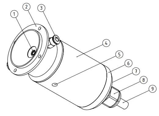
| No. | Description | No. | Description |
| ① | Infrared sensor | ⑥ | Enclosure cover |
| ② | Purge air adapter with mounting flange (4 x M4 thread) | ⑦ | Mounting holes for the mounting bracket (on the other side, not shown) (4 x M5) |
| ③ | Purge air connection for ø4 mm self-fastening compressed air hose (2 x) | ⑧ | Cable gland |
| ④ | Sensor enclosure (ø 47) | ⑨ | Intrinsically safe connection cable |
| ⑤ | Signal-LED | ||
Display Elements
| Signal-LED | |||
| For indicating operating conditions, the Signal-LED is recessed on the bottom side of the sensor enclosure. | 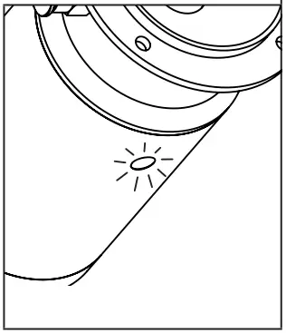 |
||
| LED indicator light | Description | ||
| red | Alarm | ||
| yellow | Fault | ||
| green | Operation | ||
Overview of HOTSPOT-X0 Interface-X1
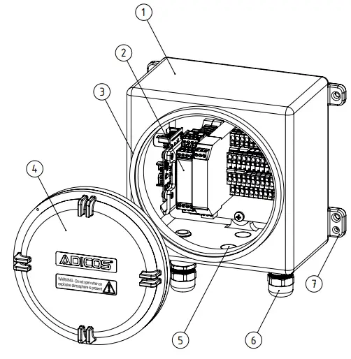
| No. | Description |
| ① | Flameproof enclosure |
| ② | Top-hat rail with explosion protection barriers, connection terminals, and interface circuit board |
| ③ | Thread for enclosure lid |
| ④ | Enclosure lid |
| ⑤ | A mounting place for additional cable glands |
| ⑥ | Cable gland (2 x) |
| ⑦ | Mounting bracket (4 x) |
Connection Terminals
Connection Terminal of HOTSPOT-X0 Sensor Unit
Terminals
The terminals are located inside the enclosure of the ADICOS HOTSPOT-X0 Sensor on the connection board. They are pluggable and can be removed from the board for easy assembly of the connecting wires.
| T1/T2 | Communication/voltage supply |
| 1 | Communication B (intrinsically safe circuit 1) |
| 2 | Communication A (intrinsically safe circuit 1) |
| 3 | Voltage supply + (intrinsically safe circuit 2) |
| 4 | Voltage supply – (intrinsically safe circuit 2) |
The sensor is supplied with a pre-assembled connection cable ex-works.
Cable Assignment
WARNING!
Risk of explosion!
The connection cable must be routed according to DIN EN 60079-14!
- Only use approved, intrinsically safe connection cables provided by GTE!
- Consider minimum bending radius!

| Color | Signal |
| green | Communication B (intrinsically safe circuit 1) |
| yellow | Communication A (intrinsically safe circuit 1) |
| brown | Voltage supply + (intrinsically safe circuit 2) |
| white | Voltage supply – (intrinsically safe circuit 2) |
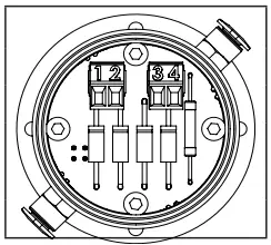
Connection Terminal of HOTSPOT-X0 Interface-X1
Connection terminals
The connection terminals are located inside the enclosure on the top-hat rail. 
| No. | Description |
| ① | Explosion protection barrier 1:
sensor communication (intrinsically safe circuit 1) |
| ② | Explosion protection barrier 2:
sensor power supply (intrinsically safe circuit 2) |
| ③ | System connection |
Sensor communication (intrinsically safe circuit 1)
| No. | Occupation |
| 9 | Cabinet shielding |
| 10 | Shield for intrinsically safe cable |
| 11 | -/- |
| 12 | -/- |
| 13 | Sensor communication B (green) |
| 14 | Sensor communication A (yellow) |
| 15 | -/- |
| 16 | -/- |
Sensor power supply (intrinsically safe circuit 2)
| No. | Occupation |
| 1 | Sensor power supply + (brown) |
| 2 | Sensor power supply – (white) |
| 3 | -/- |
System connection terminal
| No. | Occupation |
| 1 | 0 V |
| 2 | 0 V |
| 3 | M-Bus A |
| 4 | M-Bus A |
| 5 | Alarm A |
| 6 | Error A |
| 7 | LOOP A in |
| 8 | LOOP A out |
| 9 | Shield |
| 10 | Shield |
| 11 | +24 V |
| 12 | +24 V |
| 13 | M-Bus B |
| 14 | M-Bus B |
| 15 | Alarm B |
| 16 | Error B |
| 17 | LOOP B in |
| 18 | LOOP B out |
| 19 | Shield |
| 20 | Shield |
Installation
DANGER! Explosion!
Installation work may only be performed if the potentially explosive area is released for work via a risk assessment.
- De-energize the entire detector system and secure it against unintentional reactivation!
- Installation work may only be performed by specialist personnel! (–› Chap.
Personnel qualification)
Explosion Protection! Risk of explosion
In contrast to the ADICOS HOTSPOT-X0 Sensor Unit, the ADICOS HOTSPOT-X0
Interface X1 is not approved for installation within ATEX zone 0.
- Interface-X1 may only be installed outside of ATEX zone 0.
Mounting
WARNING!
Danger of malfunction and failure of the detector system Incorrect installation of ADICOS detectors can lead to faults and failures of the detector system.
- Installation work may only be performed by specialist personnel! (-> Chap. 2.3, Personnel Qualification)
Selecting the Mounting Location
Mounting Location of HOTSPOT-X0 Sensor Unit
WARNING! Correct alignment Arrangement and alignment of ADICOS detectors are highly important for reliable detection. Unfavorable placement can lead to complete ineffectiveness of the detector!
- Only experienced specialist planners may define detector position and alignment!
NOTICE!
Danger of sensitivity loss and failure of the detector system In dust environments with simultaneous high humidity, the functionality of the detector may be impaired.
- Ensure that purge air is applied! This allows you to extend the cleaning-related maintenance intervals!
- In case of high dust exposure in combination with high air humidity, contact the manufacturer for consultation!
Mounting Location of HOTSPOT-X0 Interface-X1
WARNING! Explosion danger!
Unlike the ADICOS HOTSPOT-X0 sensor unit, the ADICOS HOTSPOT-X0 interface- X1 is not approved for installation within ATEX zone 0, but only for zones 1 and 2.
- Only install ADICOS HOTSPOT-X0 Interface X1 outside ATEX zone 0!
The following aspects have to be considered when choosing the mounting location.
- Install device easily accessible and in direct vicinity to the connected sensor – but outside of ATEX zone 0.
- The mounting location must satisfy all environmental requirements specified in Chap. 10, »Specifications«.
- The mounting spot must be solid and free of vibrations.
Mounting of HOTSPOT-X0 Sensor Unit
The ADICOS HOTSPOT-X0 sensor unit is designed for two types of assembly: Flange mounting as well as wall/ceiling mounting with a quick mounting base. Flange mounting is particularly suited for detection within non-pressure-tight enclosures. Wall/ ceiling mounting is particularly suited for standalone applications.
Flange mounting
- Cut circular cutout into the enclosure using a Ø40 mm hole saw
- Using a Ø4 mm drill, drill four holes along a Ø47 mm circular path at a distance of 90° each
- Firmly bolt the HOTSPOT-X0 sensor unit to the enclosure using suitable M4 screwsWall/Ceiling Mounting
Wall mounting
Mounting mounting base
- Drill holes for dowels into the wall and/or ceiling at the mounting location at a distance of 76 mm x 102 mm
- Press in dowels
- Firmly bolt the mounting base to the wall and/or ceiling using 4 suitable screws and washers
 .
.
Mounting HOTSPOT-X0 mounting bracket
- Using the enclosed M5 cylinder-head screws, bolt the HOTSPOT-X0 mounting bracket through the radial elongated holes to the HOTSPOT-X0 sensor unit at minimum two points.
Connecting Purge Air
- Insert Ø4 mm compressed air hose into the purge air connections (2 x). Purge air specification, see chap. 10, »Technical Data«

Wall Mounting of HOTSPOT-X0 Interface-X1
- At the mounting location drill four holes (Ø 8,5 mm) in a pattern of 240 x 160 mm
- Press in suitable dowels
- Using the mounting brackets firmly bolt the enclosure to the wall using four suitable screws and washers.

Wiring
WARNING! Explosion!
Installation work may only be performed if the potentially explosive area is released for work via a risk assessment.
- De-energize the entire detector system and secure it against unintentional reactivation for all wiring work!
- Wiring may only be performed by specialist personnel! (–› Chap. 2.3)
WARNING! Risk of explosion
The connection cable must be routed per DIN EN 60079-14!
- Only use approved, intrinsically safe connection cables provided by GTE!
- Consider minimum bending radius!
WARNING! Risk of explosion
The ADICOS HOTSPOT-X0 Sensor Unit is subject to the protection principle and/ or the ignition protection type equipment protection by intrinsic safety “i”.
- Explosion protection barriers must be used!
- Only wire to the ADICOS HOTSPOT-X0 Interface X1!
Explosion protection! Risk of explosion
The ADICOS HOTSPOT-X0 Interface-X1 is subject to the protection principle and/or the ignition protection type equipment protection by flameproof enclosures “d”.
- Only use approved cable glands!
- Firmly close the enclosure lid after wiring!
Connecting HOTSPOT-X0 Sensor Unit with Connection Cable
- Open cable gland
- Open the enclosure cover by turning counterclockwise (e.g., using a 31.5 mm two-hole wrench)
- Push connection cable through the cable gland
- Wire connection cable to terminals
- Screw the enclosure cover clockwise onto the sensor enclosure and tighten hand-tight.
- Close cable gland

Wiring of ADICOS HOTSPOT-X0 Sensor Unit
- Remove the enclosure lid by rotating counter counterclockwise
- Open cable gland
- Insert sensor connection cable through the cable gland
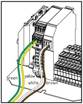
- Connect green wire (communication B) to terminal 14 of Explosion protection barrier 1 (intrinsically safe circuit 1)
- Connect yellow wire (communication A) to terminal 13 of Explosion protection barrier 1 (intrinsically safe circuit 1)
- Connect brown wire (power supply +) to terminal 1 of Explosion protection barrier 2 (intrinsically safe circuit 2)
- Connect white wire (power supply –) to terminal 2 of Explosion protection barrier 2 (intrinsically safe circuit 2)
- Connect the shield of the sensor connection cable to terminal 3 of Explosion protection Barrier 2 (intrinsically safe circuit 2)
- Close cable gland
- Mount the enclosure lid by rotating it clockwise and pulling tight
Wiring of the Fire Detection System
Depending on the system configuration connect the fire detection system to terminals 1 … 20 of the system connection terminal (–› Chap. 3.2.3). Also consult ADICOS manual No. 430-2410-001 (ADICOS AAB Operating manual).
Power Supply / Alarm and Failure 
Commissioning
DANGER! Property damage due to electrical voltage! ADICOS systems work with electrical current, which can cause equipment damage and fire if not installed properly.
- Before switching on the system, verify that all detectors are properly mounted and wired.
- Startup may be performed only by properly trained personnel.
WARNING! Risk of false alarms and device failure
The degree of protection of ADICOS detectors specified in the technical data is only guaranteed when the enclosure cover is completely closed. Otherwise, a false alarm can be triggered or the detector can fail.
- Before startup, check that all of the detector enclosure covers are completely closed, otherwise the ADICOS system will not work properly.
WARNING! Risk of explosion
The ADICOS HOTSPOT-X0 sensor unit is subject to the protection principle and or the ignition protection type equipment protection by intrinsic safety “i”.
- Explosion protection barriers must be used!
- Only wire to the ADICOS HOTSPOT-X0 Interface X1!
WARNING! Risk of explosion
The ADICOS HOTSPOT-X0 Interface-X1 unit is subject to the protection principle and/or the ignition protection type equipment protection by flameproof enclosures “d”.
- Firmly close the enclosure lid after wiring!
Maintenance
The ADICOS HOTSPOT-X0 Interface-X1 does not require maintenance.
Replacing Sensor Unit
Removing old sensor unit
- Open cable gland
- Open the enclosure cover by turning counterclockwise (e.g., using a 31.5 mm two-hole wrench) Make sure that the connection cable does not turn!
- Disconnect connection cable from terminals
- Pull enclosure cover from connection cable
Mounting new sensor unit (–› Chap. 6, Wiring)
Disposal
Return device to the manufacturer after the end of the useful life. The manufacturer ensures environmental-friendly disposal of all components.
Technical Data
Technical Data of HOTSPOT-X0 Sensor Unit
| General information | ||
| Model: | HOTSPOT-X0 Sensor Unit | |
| Article number: | 410-2401-310 | |
| Enclosure dimensions: | mm | 54 x 98 (Ø Diameter x Length) |
| Full dimensions: | mm | 123 x 54 x 65
(Length L x Ø Diameter x Width W) (Length: connection cable incl., Width: diameter purge air adapter incl.) |
| Weight: | kg | 0,6 (without connection cable) |
| Degree of protection: | IP | IP66/67 |
| Enclosure: | Stainless steel | |
|
Information regarding explosion protection |
||
| Explosion protection: |  |
II 1G Ex ia IIC T4 Ga |
| Temperature class: | T4 | |
| Device group: | II, category 1G | |
| Type approval: | Certificate per 2014/34/EU | |
|
Electrical Data |
||
| Ui[1,2] | V | 3,7 |
| Ii[1,2] | mA | 225 |
| Pi[1,2] | mW | 206 |
| Ci[1,2] | µF | negligible |
| Li[1,2] | mH | negligible |
| Uo[1,2] | V | 5 |
| Io[1,2] | mA | 80 |
| PO[1,2] | mW | 70 |
| Co[1,2] | µF | 80 |
| Lo[1,2] | µH | 200 |
| Ui[3,4] | V | 17 |
| Ii[3,4] | mA | 271 |
| Pi[3,4] | W | 1.152 |
|
Thermal, phyical data |
||
| Ambient temperature: | °C | –40 … +80 |
| Relative humidity: | % | ≤ 95 (non-condensing) |
|
Purge air |
||
| Purity classes: |
l/min |
Dust ≥ 2, Water content ≥ 3
Oil content ≥ 2 (< 0.1 mg/m3) Use non-ionized sealing air! |
| Air flow: | 2 … 8 | |
|
Sensor data |
||
| Sensor resolution: | pixel | 32 x 31 |
| Optical angle: | ° | 53 x 52 |
| Reaktion time: | s | < 1 |
| Temporal resolution: | s | 0.1 oder 1 (depends on configuration) |
|
Other |
||
| Bending radius, connection cable | mm | > 38 |
ID plate

| TYPE | Device Model | Electrical data |
CE marking |
|||||
| ANR | Article number | Prod. | Produc- tion year | IP | Degree of Protection | UI[1,2]
II[1,2] PI[1,2] U0[1,2] |
UI[3,4]
II[3,4] PI[3,4] Uo[3,4] |
|
| COM | Commu- nication number (variable) | TEMP | Ambient temperature | Information on explosion protection | ||||
| SNR | Serial number (variable) | VDC/VA | Supply voltage / Power consumption | |||||
Technical Data of HOTSPOT-X0 Interface-X1
| General information | |||
| Model: | HOTSPOT-X0 Interface-X1 | ||
| Article number | 410-2401-410 | ||
| Enclosure dimensions: | mm | 220 x 220 x 180 (Length L x Width W x Depth D) | |
| Full dimensions: | mm | 270 x 264 x 180 (L x W x D)
(Length: cable gland incl., Width: mounting brackets incl.) |
|
| Degree of protection: | IP | 66 | |
| Weight: | kg | 8 | 20 |
| Enclosure: | Aluminum | Stainless steel | |
|
Information regarding explosion protection |
|||
| Explosion protection: | II 2(1)G Ex db [ia Ga] IIC T4 Gb | ||
| Temperature class: | T4 | ||
| Device group: | II, category 2G | ||
| Type approval: | Certificate according to 2014/34/EU | ||
| IECEx certificate: | IECEx KIWA 17.0007X | ||
| ATEX certificate: | KIWA 17ATEX0018 X | ||
|
Electrical Data |
|||
| Supply voltage: | V | DC 20 … 30 | |
| Uo[1,2] | V | ≥ 17 | |
| Io[1,2] | mA | ≥ 271 | |
| Po[1,2] | W | ≥ 1,152 | |
| Uo[13,14] | V | ≥ 3,7 | |
| Io[13,14] | mA | ≥ 225 | |
| Po[13,14] | mW | ≥ 206 | |
| Ui[13,14] | V | ≤ 30 | |
| Ii[13,14] | mA | ≤ 282 | |
| CO[1,2] | µF | 0,375 | |
| LO[1,2] | mH | 0,48 | |
| LO/RO[1,2] | µH/Ω | 30 | |
| CO[13,14] | µF | 100 | |
| LO[13,14] | mH | 0,7 | |
| LO/RO[13,14] | µH/Ω | 173 | |
|
Thermal, phyical data |
||
| Ambient temperature | °C | –20 … +60 |
| Relative humidity: | % | ≤ 95 (non-condensing) |
|
Other: |
||
| Bending radius connection cable: | mm | > 38 |
ID Plate

| TYPE | Device Model | Electrical data |
CE marking |
|||||
| ANR | Article number | Prod. | Production year | IP | Degree of protection | UI[1,2]
II[1,2] PI[1,2] U0[1,2] |
UI[3,4]
II[3,4] PI[3,4] Uo[3,4] |
|
| COM | Commu- nication number (variable) | TEMP | Ambient temperature | Information on explosion protection | ||||
| SNR | Serial number (variable) | VDC/VA | Supply voltage / Power consumption | |||||
Appendix
ADICOS Mounting Bracket

Documents / Resources
 |
ADICOS Sensor Unit & Interface [pdf] Instruction Manual HOTSPOT-X0 Sensor Unit and Interface, HOTSPOT-X0, Sensor Unit and Interface, Unit and Interface, Interface |


