![]() MDM300
MDM300
Sampling System
User Manual 97232 Issue 1.5
October 2024
Instruments MDM300 Sampling System
Please fill out the form(s) below for each instrument that has been purchased.
Use this information when contacting Michell Instruments for service purposes.
| Instrument | |
| Code | |
| Serial Number | |
| Invoice Date | |
| Location of Instrument | |
| Tag No | |
| Instrument | |
| Code | |
| Serial Number | |
| Invoice Date | |
| Location of Instrument | |
| Tag No | |
| Instrument | |
| Code | |
| Serial Number | |
| Invoice Date | |
| Location of Instrument | |
| Tag No |
 For Michell Instruments’ contact information please go to www.ProcessSensing.com
MDM300 Sampling System
© 2024 Michell Instruments
This document is the property of Michell Instruments Ltd. and may not be copied or otherwise reproduced, communicated in any way to third parties, nor stored in any Data Processing System without the express written authorization of Michell Instruments Ltd.
Safety
The manufacturer has designed this equipment to be safe when operated using the procedures detailed in this manual. The user must not use this equipment for any other purpose than that stated. Do not subject the equipment to conditions outside of the specified operating limits. This manual contains operating and safety instructions, which must be followed to ensure the safe operation and to maintain the equipment in a safe condition. The safety instructions are either warnings or cautions issued to protect the user and the equipment from injury or damage. Use competent personnel using good engineering practice for all procedures in this manual.
Electrical Safety
The instrument is designed to be completely safe when used with options and accessories supplied by the manufacturer for use with the instrument.
Pressure Safety
DO NOT permit pressures greater than the safe working pressure to be applied to the instrument.
The specified safe working pressure will be as follows (refer to Appendix A – Technical Specifications):
Low pressure: 20 barg (290 psig)
Medium pressure: 110 barg (1595 psig)
High pressure: 340 barg (4931 psig)
![]() WARNING
WARNING
The flowmeter should never be pressurized.
Always expand a pressurized sample to atmospheric pressure before it enters the flow meter.
Toxic Materials
The use of hazardous materials in the construction of this instrument has been minimized. During normal operation it is not possible for the user to come into contact with any hazardous substance which might be employed in the construction of the instrument. Care should, however, be exercised during maintenance and the disposal of certain parts.
Repair and Maintenance
The instrument must be maintained either by the manufacturer or an accredited service agent. Refer to www.ProcessSensing.com for details of Michell Instruments’ worldwide offices contact information
Calibration
The recommended calibration interval for the MDM300 Hygrometer is 12 months. The instrument should be returned to the manufacturer, Michell Instruments, or one of their accredited service agents for recalibration.
Safety Conformity
This product meets the essential protection requirements of the relevant EU directives. Further details of applied standards may be found in the product specification.
Abbreviations
The following abbreviations are used in this manual:
AC alternating current barg pressure unit (=100 kP or 0.987 atm) gauge
ºC degrees Celsius
ºF degrees Fahrenheit
Nl/min liters per minute
kg kilogram(s)
lb pound(s) mm millimeters “ inch(es)psig pounds per square inch gauge scfh standard cubic feet per hour
Warnings
The following general warning listed below is applicable to this instrument. It is repeated in the text in the appropriate locations.
![]() Where this hazard warning symbol appears in the following sections, it is used to indicate areas where potentially hazardous operations need to be carried out.
Where this hazard warning symbol appears in the following sections, it is used to indicate areas where potentially hazardous operations need to be carried out.
INTRODUCTION
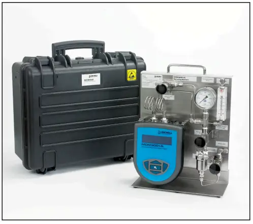
The MDM300 panel-mount sampling system offers a complete package for conditioning of a sample, prior to measurement with an MDM300 or MDM300 I.S.
It is contained within an optional flight case which allows easy transport of everything required to make the measurements. The anti-static construction of the case makes it suitable for use in hazardous areas.

INSTALLATION
2.1 Safety
![]() It is essential that the installation of the electrical and gas supplies to this instrument be undertaken by qualified personnel.
It is essential that the installation of the electrical and gas supplies to this instrument be undertaken by qualified personnel.
2.2 Unpacking the Instrument
The shipping box will contain the following:
- MDM300 Panel-Mount Sampling System
- Flight case (optional)
- 2.5mm Allen key
- 2 x 2.5mm hex bolts
- 2 x 1/8” NPT to 1/8” Swagelok ® adaptors
1. Open the box. If a flight case was ordered, the sampling system will be packaged within it.
2. Remove the sampling panel (or flight case, if ordered) from the box, along with the fittings.
3. Save all packing materials in case it is necessary to return the instrument.
2.3 Environmental Requirements
Refer to the user’s manual for information on acceptable environmental conditions in which to operate the MDM300.
2.4 Preparing the Sampling System for Operation
To prepare the system for operation, it is necessary to install the MDM300 into the sampling system as follows:
- Wrap PTFE tape (not supplied), around the ends of the 1/8” NPT to 1/8” Swagelok tube fittings and install into the orifice adaptors fitted to the MDM300. Ensure that the orifice port adaptors in the MDM300 are both large bore type (see relevant user’s manual for more details).

- Locate the MDM300 in the position shown below.

- Connect the coiled tubes to the inlet and outlet of the MDM300. Ensure that the 1/8” Swagelok ® nuts are finger tight.

- Secure the instrument to the mounting posts using the supplied 2.5mm hex bolts and allen key.

- Use a wrench/spanner to finish tightening the 1/8″ Swage100, nuts on the inlet/outlet to ensure there are no leaks. The body of the 1/8″ NPT to 1/8″ Swageloklt adaptor should be held securely with another wrench/spanner while the nuts are tightened to prevent any movement.

2.5 Controls, Indicators and Connectors

| 1 | Outlet Metering Valve | Used to regulate sample flow for system pressure measurements Should be fully open for system pressure measurements |
| 2 | Pressure Gauge | Gauge showing the sample pressure across the sensor cell |
| 3 | Sample Vent | Fitted with either a silencer or Swagelok® tube fitting to enable a vent line to be connected |
| 4 | Flow Meter | For flow indication |
| 5 | Inlet Metering Valve | Used to regulate sample flow for atmospheric pressure measurements Should be fully open for system pressure measurements |
| 6 | Bypass Port | Outlet from the bypass path Can optionally be connected to a vent line during operation |
| 7 | Sample Inlet | For connection to the sample gas line Refer to Section 3.1 for more information on making connections to the system |
| 8 | Bypass Metering Valve | Used for regulating the flow rate through the bypass path |
Table 1 Controls, Indicators and Connectors
OPERATION
3.1 Sample Gas Connection
Gas is introduced to the system by connecting the sample take-off line to the GAS IN port, as shown in Figure 8.
If required, connect a vent line to the BYPASS port, and to the flowmeter vent (if fitted).

3.2 Operating Procedure
- Connect an instrument to the sample gas as detailed in Section 3.1.
- Fully open the isolation valve.
- Refer to the Operation Guide section in the relevant MDM300 user’s manual for condition specific instructions on operation.
- Depending on the sample pressure it may be necessary to use the bypass flow control to overcome sample flow control difficulties.
3.3 Sampling Hints
Measurement of moisture content is a complex subject, but does not need to be difficult.
This section aims to explain the common mistakes made in measurement situations, the causes of the problem, and how to avoid them. Mistakes and bad practices can cause the measurement to vary from the expectation; therefore a good sampling technique is crucial for accurate and reliable results.
Transpiration and Sampling Materials
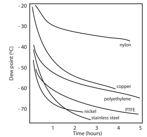
All materials are permeable to water vapor, as the water molecule is extremely small compared to the structure of solids, even when compared to the crystalline structure of metals. The graph to the right shows the dew point inside tubing of different materials when purged with very dry gas, where the exterior of the tubing is in the ambient environment.
Many materials contain moisture as part of their structure, particularly organic materials (natural or synthetic), salts (or anything which contains them) and anything which has small pores. It is important to ensure that the materials used are suitable for the application.
If the partial water vapor pressure exerted on the outside of a compressed air line is higher than on the inside, the atmospheric water vapor will naturally push through the porous medium causing water to migrate into the pressurized air line. This effect is called transpiration.
Adsorption and Desorption
Adsorption is the adhesion of atoms, ions, or molecules from a gas, liquid, or dissolved solid to the surface of a material, creating a film. The rate of adsorption is increased at higher pressures and lower temperatures.
Desorption is the release of a substance from or through the surface of a material. In constant environmental conditions, an adsorbed substance will remain on a surface almost indefinitely. However, as the temperature rises, so does the likelihood of desorption occurring.
In practical terms, as the temperature of the environment fluctuates, water molecules are adsorbed and desorbed from the internal surfaces of the sample tubing, causing small fluctuations in the measured dew point.
Sample Tubing Length
The sample point should always be as close to the critical measurement point as possible, in order to obtain a truly representative measurement. The length of the sample line to the sensor or instrument should be as short as possible. Interconnection points and valves trap moisture, so using the simplest sampling arrangement possible will reduce the time it takes for the sample system to dry out when purged with dry gas. Over a long tubing run, water will inevitably migrate into any line, and the effects of adsorption and desorption will become more apparent. It is clear from the graph shown above that the best materials to resist transpiration are stainless steel and PTFE.
Trapped Moisture
Dead volumes (areas which are not in a direct flow path) in sample lines, hold onto water molecules which are slowly released into the passing gas; this results in increased purge and response times, and wetter than expected readings. Hygroscopic materials in filters, valves (e.g. rubber from pressure regulators) or any other parts of the system can also trap moisture.
Sample Conditioning
Sample conditioning is often necessary to avoid exposure of sensitive measuring components to liquids and other contaminants which may cause damage or affect the accuracy over time, depending on the measurement technology.
Particulate filters are used for removing dirt, rust, scale and any other solids that may be in a sample stream. For protection against liquids, a coalescing filter should be used. The membrane filter is a more expensive but highly effective alternative to a coalescing filter. It provides protection from liquid droplets, and can even stop flow to the analyzer completely when a large slug of liquid is encountered.
Condensation and Leaks

Maintaining the temperature of the sample system tubing above the dew point of the sample is vital to prevent condensation. Any condensation invalidates the sampling process as it changes the water vapor content of the gas being measured. Condensed liquid can alter the humidity elsewhere by dripping or running to other locations where it may re-evaporate.
The integrity of all connections is also an important consideration, especially when sampling low dew points at an elevated pressure. If a small leak occurs in a high pressure line, gas will leak out but vortices at the leak point and a negative vapor pressure differential will also allow water vapor to contaminate the flow.
Flow Rates
Theoretically flow rate has no direct effect on the measured moisture content, but in practice it can have unanticipated effects on response speed and accuracy. The optimal flow rate varies depending on the measurement technology.
MDM300 I.S. flow rate 0.2 to 0.5 Nl/min (0.5 to 1 scfh)
MDM300 flow rate 0.2 to 1.2 Nl/min (0.5 to 1.2 scfh)
![]() WARNING
WARNING
The flowmeter should never be pressurized.
Always expand a pressurized sample to atmospheric pressure before it enters the flow meter.
An inadequate flow rate can:
- Accentuate adsorption and desorption effects on the gas passing through the sampling system.
- Allow pockets of wet gas to remain undisturbed in a complex sampling system, which will then gradually be released into the sample flow.
- Increase the chance of contamination from back diffusion: ambient air that is wetter than the sample can flow from the exhaust back into the system. A longer exhaust (sometimes called a pigtail) can also help alleviate this problem.
An excessively high flow rate can: - Introduce back pressure, causing slower response times and unpredictable effects on equipment such as humidity generators.
- Result in a reduction in heating capabilities of the sensor tile during the initialization period. This is most apparent with gases that have a high thermal conductivity such as hydrogen and helium.
MAINTENANCE
4.1 General Maintenance Guidelines
Routine maintenance of the system is confined to filter element replacement and regular recalibration of the MDM300 or MDM300 I.S. sensor. For specific details on replacing filter elements, please see Section 4.2.
In most applications, annual recalibration ensures that the stated accuracy of the MDM300 Advanced Dew-Point Hygrometer is maintained. The exchange sensor scheme is the most efficient method of providing accurate annual recalibration with minimum downtime.
Please contact Michell Instruments for more details.
Prior to recalibration being necessary, an exchange sensor can be ordered from Michell Instruments or any authorized dealer. Once the sensor and calibration certificate has been received it can be fitted and the original sensor returned to Michell Instruments.
For more details of recalibration of the MDM300 please see the relevant user’s manual.
4.2 Filter Element Replacement
Frequency of filter element replacement is primarily dependent upon the quantity of contaminants present in the sample gas. If the gas is heavily laden with particulates or liquids it is recommended to inspect the filter element on a regular basis initially, and increase the time between inspections if the filter is found to be in good condition.
It is imperative that all filters are replaced before they become saturated. If a filter element becomes saturated with contaminants there is a possibility that the performance of the filter will be reduced, and contamination of the MDM300 sensor could occur.
![]() Before attempting to replace the filter always disconnect the Sampling System from the sample gas and ensure that the system is depressurized.
Before attempting to replace the filter always disconnect the Sampling System from the sample gas and ensure that the system is depressurized.
To replace a particulate or coalescing filter element, proceed as follows:
- Disconnect the U-shaped section of Swagelok® tubing from the filter drain.

- Unscrew and remove the filter bowl and then the filter element. NOTE: the filter bowl is sealed with an O-ring.
- Discard the old used filter element and replace with a new filter element Order codes:
MDM300-SAM-PAR – particulate element MDM300-SAM-COA – coalescing element - Replace the filter bowl, ensuring the O-ring is correctly seated and reconnect the tube to the drain port.
NOTE: Tighten both securely.
To replace the glycol absorption cartridge, proceed as follows:

- Loosen union bonnet nut with open end spanner/wrench. Support body to minimize strain on pipe or tubing.
- Unscrew union nut and remove assembly.
NOTE: Union nut, bonnet, spring and retaining ring remain together as an assembly. - Gently tap filter element on side to break loose from tapered seating area.
- Insert new glycol absorption cartridge. Tap lightly to reseat in tapered bore. Order code: MDM300-SAM-PNL-GLY
- Inspect gasket and mating surfaces on bonnet and body. Clean as required. Replacement of the gasket is recommended.
Appendix A Technical Specifications
| Enclosure | |
| Dimensions | 300 x 400 x 150mm (11.81 x 15.75 x 5.91″) (w x h x d) |
| Materials | ABS (anti-static) |
| Ingress Protection | IP67 / NEMA4 |
| Sampling System | |
| Pressure Range | Low pressure: 20 barg (290 psig) Medium pressure: 110 barg (1595 psig) High pressure: 340 barg (4931 psig) |
| Flow Rate | MDM300 0.2…1.2 NI/min (0.4…2.54 scfh) MDM300 I.S. 0.2…0.5 NI/min (0.4…1.1 scfh) |
| Gas Wetted Materials | 316 stainless steel |
| Gas Connections | Depending on model: Legris quick release – accepts 6mm 0/D PTFE (LOW PRESSURE VERSION ONLY) 1/8″ Swagelok® 6mm Swagelok® |
| Components | |
| Valves | Inlet isolation valve, 2 x sample flow control valves, Bypass flow control valve |
| Filtration | Options of: Particulate Coalescing |
| Pressure Gauge | Depending on model: Low pressure: 0…25 barg (0…362 psig) Medium pressure: 0…137 barg (0…1987 psig) High pressure: 0…413 barg (0…5990 psig) |
| Vent | Atmospheric pressure only – DO NOT pressurize vent Options of: Silencer 1/8″ Swagelok® 6mm Swagelok® |
Appendix B Quality, Recycling & Warranty Information
Michell Instruments is dedicated to complying to all relevant legislation and directives. Full information can be found on our website at: www.ProcessSensing.com/en-us/compliance/
This page contains information on the following directives:
- Anti-Facilitation of Tax Evasion Policy
- ATEX Directive
- Calibration Facilities
- Conflict Minerals
- FCC Statement
- Manufacturing Quality
- Modern Slavery Statement
- Pressure Equipment Directive
- REACH
- RoHS
- WEEE
- Recycling Policy
- Warranty and Returns
This information is also available in PDF format.
Appendix C Return Document & Decontamination Declaration
Decontamination Certificate
IMPORTANT NOTE: Please complete this form prior to this instrument, or any components, leaving your site and being returned to us, or, where applicable, prior to any work being carried out by a Michell engineer at your site.
| Instrument | Serial Number | ||||||
| Warranty Repair? | YES | NO | Original PO # | ||||
| Company Name | Contact Name | ||||||
| Address | |||||||
| Telephone # | E-mail address | ||||||
| Reason for Return /Description of Fault: | |||||||
| Has this equipment been exposed (internally or externally to any of the following? Please circle (YES/NO) as applicable and provide details below | |||||||
| Biohazards | YES | NO | |||||
| Biological agents | YES | NO | |||||
| Hazardous chemicals | YES | NO | |||||
| Radioactive substances | YES | NO | |||||
| Other hazards | YES | NO | |||||
| Please provide details of any hazardous materials used with this equipment as indicated above (use continuation sheet if necessary) | |||||||
| Your method of deaning/decontamination | |||||||
| Has the equipment been cleaned and decontaminated? | I YES | I NOT NECESSARY | |||||
| Michell Instruments will not accept instruments that have been exposed to toxins, radio-activity or bio-hazardous materials. For most applications involving solvents, acidic, basic, flammable or toxic gases a simple purge with dry gas (dew point <-30°C) over 24 hours should be sufficient to decontaminate the unit prior to return. Work will not be carried out on any unit that does not have a completed decontamination declaration. | |||||||
| Decontamination Declaration | |||||||
| I declare that the information above is true and complete to the best of my knowledge, and it is safe for Michell personnel to service or repair the returned instrument. | |||||||
| Name (Print) | Position | ||||||
| Signature | Date | ||||||
Documents / Resources
 |
MICHELL Instruments MDM300 Sampling System [pdf] User Manual MDM300, MDM300 Sampling System, Sampling System, System |


