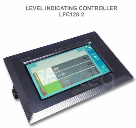
![]() Level Indicating
Level Indicating
Controller LFC128-2
Pandhuan pangguna kanggo tingkat nuduhake CONTROLLER LFC128-2
LFC128-2-MN-EN-01 JUN-2020
LFC128-2 Tingkat Lanjut Tampilan Controller
Dokumen iki ditrapake kanggo produk ing ngisor iki
| SKU | LFC128-2 | HW Ver. | 1.0 | FW Ver. | 1.1 |
| Kode Barang | LFC128-2 | Pengontrol Indikator Level, 4AI/DI, 4DI, 4xRelay, 1xPulse Output, 2 x RS485/ModbusRTU-Slave Communication | |||
Log Pangowahan Fungsi
| HW Ver. | FW Ver. | Tanggal Rilis | Fungsi Ganti |
| 1.0 | 1.1 | JUNI-2020 | |
Pambuka
LFC128-2 minangka pengontrol tampilan tingkat lanjut. Produk kasebut nggabungake antarmuka Modbus RTU kanggo mbantu PLC / SCADA / BMS lan port IoT apa wae bisa nyambung menyang monitor. LFC128-2 nduweni desain sing prasaja nanging kuat kanthi 4 AI / DI, 4 DI, 4 Relay, 1 Output pulsa Pulse, 2 RS485 Slave ModbusRTU supaya bisa nyambung karo macem-macem piranti kanthi gampang. Kanthi teknologi canggih sing nyedhiyakake stabilitas lan linuwih sing dhuwur, akeh fungsi, instalasi sing gampang karo layar tutul lan antarmuka sing ramah mbantu tingkat monitor kanthi visual.
Spesifikasi
| Input Digital | 04 x Ports, opto-coupler, 4.7 kohms input resisrtance, 5000V rms isolation, Logic 0 (0-1VDC), Logic 1 (5-24VDC), Functions: logic status 0/1 or Pulse counting (32 bit counter with max 4kHz pulse) |
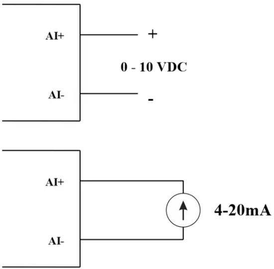
| Masukan Analog | 04 x Ports, select between 0-10VDC input or 0-20mA input, 12 bit Resolution, can be configured as Digital input by DIP switch (max 10VDC input) The AI1 port is a 0-10 VDC / 4-20 mA level sensor connection port |
| Relay Output | 04 x Ports, electro-mechanical Relays, SPDT, contact rating 24VDC/2A or 250VAC/5A, LED indicators |
| Output Pulsa | 01 x Ports, open-collector, opto-isolation, max 10mA and 80VDC, On/off control, Pulser (max 2.5Khz, max 65535 Pulses) or PWM (max 2.5Khz) |
| Komunikasi | 02 x ModbusRTU-Slave, RS485, kacepetan 9600 utawa 19200, indikator LED |
| Tombol reset | For resetting 02 x RS485 Slave port to default setting (9600, None parity, 8 bit) |
| Jinis layar | Layar tutul |
| sumber daya | 9..36VDC |
| Konsumsi | 200mA @ 24VDC sumber |
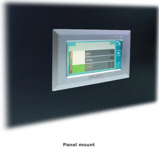
| Tipe pemasangan | Panel mount |
| Blok Terminal | pitch 5.0mm, rating 300VAC, ukuran kabel 12-24AWG |
| Suhu kerja / asor | 0..60 degC / 95% RH non-kondensasi |
| ukuran | H93xW138xD45 |
| bobot net | 390g wuh |
Gambar Produk


Prinsip Operasi

5.1 Komunikasi Modbus

02 x RS485/ModbusRTU-Slave
Protokol: Modbus RTU
alamat: 1 – 247, 0 is the Broadcast address
Baud rate: 9600, 19200
Paritas: ora ana, ganjil, malah
- Indikator status LED:
- Led on: modbus communication OK
- Led blinking: received data but modbus communication incorrect, due to wrong Modbus configuration: address, baudrate
- Led off: LFC128-2 received no data, check the connection
Memmap ndhaptar
READ nggunakake printah 03, WRITE nggunakake printah 16
Konfigurasi standar:
- Alamat: 1
- Baudrate slave 1: 9600
- Parity slave 1: none
- Baudrate slave 2: 9600
- Parity slave 2: none
| Modbus Ndhaptar | Hex adr | # of registers |
Katrangan | Range | Default | Format | Properti | Komentar |
| 0 | 0 | 2 | informasi piranti | LFC1 | senar | maca | ||
| 8 | 8 | 1 | DI1 DI2: digital status | 0-1 | uint8 | maca | H_byte: DI1 L_byte: DI2 | |
| 9 | 9 | 1 | DI3 DI4: digital status | 0-1 | uint8 | maca | H_byte: DI3 L_byte: DI4 | |
| 10 | A | 1 | AI1 AI2: digital status | 0-1 | uint8 | maca | H_byte: AI1 L_byte: AI2 | |
| 11 | B | 1 | AI3 AI4: digital status | 0-1 | uint8 | maca | H_byte: AI3 L_byte: AI4 | |
| 12 | C | 1 | AI1: nilai analog | uint16 | maca | |||
| 13 | D | 1 | AI2: nilai analog | uint16 | maca | |||
| 14 | E | 1 | AI3: nilai analog | uint16 | maca | |||
| 15 | F | 1 | AI4: nilai analog | uint16 | maca | |||
| 16 | 10 | 2 | AI1: nilai skala | ngambang | maca | |||
| 18 | 12 | 2 | AI2: nilai skala | ngambang | maca | |||
| 20 | 14 | 2 | AI3: nilai skala | ngambang | maca | |||
| 22 | 16 | 2 | AI4: nilai skala | ngambang | maca | |||
| 24 | 18 | 1 | relay 1 | 0-1 | uint16 | maca | ||
| 25 | 19 | 1 | relay 2 | 0-1 | uint16 | maca | ||
| 26 | 1A | 1 | relay 3 | 0-1 | uint16 | maca | ||
| 27 | 1B | 1 | relay 4 | 0-1 | uint16 | maca | ||
| 28 | 1C | 1 | mbukak kolektor ctrl | 0-3 | uint16 | Maca / Nulis | 0: mati 1: on 2: pwm, pulsa terus menerus 3: pulsa, nalika nomer pulsa cukup, ctrl = 0 | |
| 30 | 1E | 2 | counter DI1 | uint32 | Maca / Nulis | counter bisa ditulis, bisa dibusak | ||
| 32 | 20 | 2 | counter DI2 | uint32 | Maca / Nulis | counter bisa ditulis, bisa dibusak | ||
| 34 | 22 | 2 | counter DI3 | uint32 | Maca / Nulis | counter bisa ditulis, bisa dibusak | ||
| 36 | 24 | 2 | counter DI4 | uint32 | Maca / Nulis | counter bisa ditulis, bisa dibusak | ||
| 38 | 26 | 2 | counter AI1 | uint32 | Maca / Nulis | counter writable, erasable, max frequency 10Hz | ||
| 40 | 28 | 2 | counter AI2 | uint32 | Maca / Nulis | counter writable, erasable, max frequency 10Hz | ||
| 42 | 2A | 2 | counter AI3 | uint32 | Maca / Nulis | counter writable, erasable, max frequency 10Hz | ||
| 44 | 2C | 2 | counter AI4 | uint32 | Maca / Nulis | counter writable, erasable, max frequency 10Hz | ||
| 46 | 2E | 2 | DI1: time on | uint32 | Maca / Nulis | sek | ||
| 48 | 30 | 2 | DI2: time on | uint32 | Maca / Nulis | sek | ||
| 50 | 32 | 2 | DI3: time on | uint32 | Maca / Nulis | sek | ||
| 52 | 34 | 2 | DI4: time on | uint32 | Maca / Nulis | sek | ||
| 54 | 36 | 2 | AI1: time on | uint32 | Maca / Nulis | sek | ||
| 56 | 38 | 2 | AI2: time on | uint32 | Maca / Nulis | sek | ||
| 58 | 3A | 2 | AI3: time on | uint32 | Maca / Nulis | sek | ||
| 60 | 3C | 2 | AI4: time on | uint32 | Maca / Nulis | sek | ||
| 62 | 3E | 2 | DI1: time off | uint32 | Maca / Nulis | sek | ||
| 64 | 40 | 2 | DI2: time off | uint32 | Maca / Nulis | sek | ||
| 66 | 42 | 2 | DI3: time off | uint32 | Maca / Nulis | sek | ||
| 68 | 44 | 2 | DI4: time off | uint32 | Maca / Nulis | sek | ||
| 70 | 46 | 2 | AI1: time off | uint32 | Maca / Nulis | sek | ||
| 72 | 48 | 2 | AI2: time off | uint32 | Maca / Nulis | sek | ||
| 74 | 4A | 2 | AI3: time off | uint32 | Maca / Nulis | sek | ||
| 76 | 4C | 2 | AI4: time off | uint32 | Maca / Nulis | sek | ||
| 128 | 80 | 2 | counter DI1 | uint32 | maca | counter ora bisa nulis, mbusak | ||
| 130 | 82 | 2 | counter DI2 | uint32 | maca | counter ora bisa nulis, mbusak | ||
| 132 | 84 | 2 | counter DI3 | uint32 | maca | counter ora bisa nulis, mbusak | ||
| 134 | 86 | 2 | counter DI4 | uint32 | maca | counter ora bisa nulis, mbusak | ||
| 136 | 88 | 2 | counter AI1 | uint32 | maca | counter ora bisa nulis, mbusak; frekuensi maksimum 10Hz | ||
| 138 | 8A | 2 | counter AI2 | uint32 | maca | counter ora bisa nulis, mbusak; frekuensi maksimum 10Hz | ||
| 140 | 8C | 2 | counter AI3 | uint32 | maca | counter ora bisa nulis, mbusak; frekuensi maksimum 10Hz | ||
| 142 | 8E | 2 | counter AI4 | uint32 | maca | counter ora bisa nulis, mbusak; frekuensi maksimum 10Hz | ||
| 256 | 100 | 1 | modbus alamat budak | 1-247 | 1 | uint16 | Maca / Nulis |
|
| 257 | 101 | 1 | modbus baudrate slave 1 | 0-1 | 0 | uint16 | Maca / Nulis |
0: 9600, 1: 19200 |
| 258 | 102 | 1 | budak paritas modbus 1 | 0-2 | 0 | uint16 | Maca / Nulis |
0: ora ana, 1: ganjil, 2: genap |
5.2 Tombol Reset
When holding the reset button for 4 seconds, LFC 128-2 will reset the default configuration to 02 x RS485 / Modbus
RTU-Slave.
Konfigurasi Modbus RTU Default:
- Alamat: 1
- Baud Rate: 9600
- Paritas: ora ana
5.3 Masukan Digital

Spesifikasi:
- 04 channels DI, isolated
- Input Resistance: 4.7 kΏ
- Isolasi Voltage: 5000vm
- Logic level 0: 0-1V
- Logic level 1: 5-24V
- Fungsi:
- Read logic 0/1
- Pulsa Counter
5.3.1 Maca negara logis 0/1
Nilai logika ing Modbus Memory Map: 0-1
Ndhaptar kanggo nyimpen nilai logika ing Peta Memori Modbus:
- DI1__DI2: digital status: stores the logical state of channel 1 and channel 2.
H_byte: DI1
L_byte: DI2 - DI3__DI4: digital status: store the logical state of channel 3 and channel 4.
H_byte: DI3
L_byte: DI4
5.3.2 Pulse Counter
Nilai counter ing Modbus Memory Map, nalika nambahake nomer ngluwihi ambang, bakal kanthi otomatis bali: 0 4294967295 (32bits)
Register sing nyimpen nilai Counter ing Modbus Memory Map ora bisa dibusak:
- Counter DI1: nyimpen status logika saluran 1
- Counter DI2: nyimpen status logika saluran 2
- Counter DI3: store the logic state of channel 3
- Counter DI4: nyimpen status logika saluran 4
Register sing nyimpen nilai Counter ing Modbus Memory Map ora bisa dibusak: - None reset counter DI1: stores the logic state of channel 1
- None reset counter DI2: stores the logic state of channel 2
- None reset counter DI3: stores the logic state of channel 3
- None reset counter DI4: stores the logic state of channel 4
Pulse Counter Mode:
Low-speed pulse count less than 10Hz with filter, anti-jamming:
- Set register “counter DI1: filter time” = 500-2000: Channel 1 counts pulses less than 10Hz
- Set register “counter DI2: filter time” = 500-2000: Channel 2 counts pulses less than 10Hz
- Set register “counter DI3: filter time” = 500-2000: Channel 3 counts pulses less than 10Hz
- Set register “counter DI4: filter time” = 500-2000: Channel 4 counts pulses less than 10Hz
- High-speed pulse count with max 2KHz frequency without filter:
- Set register “counter DI1: filter time” = 1: channel 1 counts pulses with Fmax = 2kHz
- Set register “counter DI2: filter time” = 1: channel 2 counts pulses with Fmax = 2kHz
- Set register “counter DI3: filter time” = 1: channel 3 counts pulses with Fmax = 2kHz
- Set register “counter DI4: filter time” = 1: channel 4 counts pulses with Fmax = 2kHz
5.4 Input Analog
04 saluran AI, tanpa isolasi (AI1 minangka input sensor level 4-20mA / 0-5 VDC / 0-10 VDC)
Gunakake DIP SW kanggo ngatur input Analog: 0-10V, 0-20mA
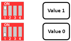
| Nilai | Type of AI |
| 0 | 0-10 V |
| 1 | 0-20 mA |
Tipe input:
- Ukuran voltage: 0-10V
- Measure current: 0-20mA
- The configuration for AI reads the same logical state as DI, but it is not isolated with a pulse range of 0-24V
Impedansi input:
- Ukuran voltage: 320 kΏ
- Measure the current: 499 Ώ
5.4.1 Maca Nilai Analog
Resolusi 12 bit
Non-Linearitas: 0.1%
Nilai analog ing Modbus Memory Map: 0-3900
Daftar nilai analog ing Peta Memori Modbus:
- AI1 analog value: store the Analog value of channel 1
- AI2 analog value: stores the Analog value of channel 2
- AI3 analog value: store the Analog value of channel 3
- AI4 analog value: store the Analog value of channel 4
5.4.2 konfigurasi AI dianggo minangka DI
Ora iso diisolasi
AI Konfigurasi AI kanggo maca negara logika padha DI karo pulsa amptegangan saka 0-24V
Ana 2 counter threshold AIx: logic threshold 0 lan counter AIx: threshold logic 1 ing tabel modbus: 0-4095
- Analog Analog value of AI <counter AIx: threshold logic 0: is considered Logic 0 status of AI
- Analog Analog value of AI> counter AIx: threshold logic 1: is considered to be Logic 1 state of AI
- Counter AIx: threshold logic 0 = <Analog value of AI <= counter AIx: threshold logic 1: is considered to be the constant logic state
Logika Nilai status logis AI ing tabel Peta Memori Modbus: 0-1
Register nyimpen nilai logis ing Modbus Memory Map:
- AI1___AI2: digital status: stores the logical state of channel 1 and channel 2.
H_byte: AI1
L_byte: AI2 - AI3___AI4: digital status: stores the logical state of channel 1 and channel 2.
H_byte: AI3
L_byte: AI4
5.4.3 Pulse Counter AI max 10Hz
Nilai counter ing Modbus Memory Map, nalika nambahake nomer ngluwihi ambang, bakal kanthi otomatis bali: 0 4294967295 (32bits)
Register sing nyimpen nilai Counter ing Modbus Memory Map ora bisa dibusak:
- Counter AI1: stores the logic state of channel 1
- Counter AI2: save logic state of channel 2
- Counter AI3: save logic state of channel 3
- Counter AI4: save logic state of channel 4
Register sing nyimpen nilai Counter ing Modbus Memory Map ora bisa dibusak: - None reset counter AI1: stores the logic state of channel 1
- None reset counter AI2: stores the logic state of channel 2
- None reset counter AI3: stores the logic state of channel 3
- None reset counter AI4: save logic state of channel 4
5.5 Relay
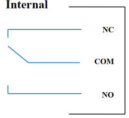
04 channel Relay SPDT NO / NC
Contact rating: 2A / 24VDC, 0.5A / 220VAC
There are status LEDs:
- Led on: Close Contact
- Led off: Open Contact
| Default Relay Register | Status of relays when resetting power supplies |
| 3 | Operate according to the Alarm configuration |
Konfigurasi Weker:
- HIHI : Relay 4 On
- HI : Relay 3 On
- LO : Relay 2 On
- LOLO: Relay 1 On
5.6 Output Pulse

01 isolated open-collector channel
Opto-coupler: Source current Imax = 10mA, Vceo = 80V
Fungsi: On / Off, pulse generator, PWM
5.6.1 Fungsi On/Off
Set the Open-collector register in the Modbus Memory Map table:
- Set Open-collector register: 1 => Pulse Output ON
- Set Open-collector register: 0 => Pulse Output OFF
5.6.2 Pulse generator
Output pulsa ngirim maksimal 65535 pulsa, kanthi Fmax 2.5kHz
Konfigurasi register ing ngisor iki ing tabel Modbus Memory Map:
- Set register “open collector: pulse number”: 0-65535 => Pulse Number = 65535: broadcast 65535 pulses
- Set register “open collector: time cycle”: (0-65535) x0.1ms => Time Cycle = 4: Fmax 2.5kHz
- Set register “open collector: time on”: (0-65535) x0.1ms => Time On: is the logic time 1 of the pulse
- Set the register “open collector ctrl” = 3 => configure the Pulse Output to generate a pulse and start to pulse, generate a sufficient number of pulses in the “open collector: pulse number” register => stop pulse generator and register ” open collector ctrl ”= 0
5.6.3 PWM
Frekuensi maksimal 2.5kHz
Konfigurasi register ing ngisor iki ing tabel Modbus Memory Map:
- Set the register “open collector ctrl” = 2 => configure Pulse Output PWM function
- Set register “open collector: time cycle”: (0-65535) x0.1ms => Time Cycle = 4: Fmax 2.5kHz
- Set register “open collector: time on”: (0-65535) x0.1ms => Time On: is the logic time 1 of the pulse
Instalasi
6.1 Cara instalasi
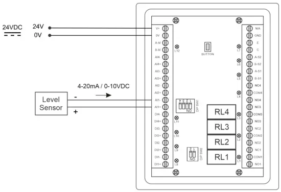
 6.2 Wiring karo Sensor Level

Konfigurasi
7.1 Layar Ngarep

LAYAN: Switch to 2nd screen with more detailed information
Tandha: Show Level Alert
RUMAH: Bali menyang Layar Ngarep
KONFIG. (Default Password: a): Go to Setting Screen
7.2 Layar setelan (Sandhi Default: a)
7.2.1 Layar 1
![daviteq LFC128 2 Advanced Level Display Controller - Home Screen 1] '](https://manuals.plus/wp-content/uploads/2025/08/daviteq-LFC128-2-Advanced-Level-Display-Controller-Home-Screen-1-550x305.png)
ADC: Raw signal value of channel AI1
Level (Unit): The level corresponds to the ADC signal after configuration
Decimal Places Level:Decimal number of digits after the dot of Level 0-3 (00000, 1111.1, 222.22, 33.333)
Unit level: level units, 0-3 (0: mm, 1: cm, 2: m, 3: inch)
Ing 1: Enter the ADC value after putting 4 mA / 0 VDC into AI1 for calibration at 0 level
Skala 1: The level value displayed corresponds to the value entered in In 1 (usually 0)
Ing 2: Enter the ADC value after putting 20 mA / 10 VDC into AI1 for calibration at Full level
Skala 2: The level value displayed corresponds to the value entered in In 2
Span Level: Maximum value of Level (Span Level ≥ Scale 2)
Decimal Places Volume: Decimal number of digits after the dot of Volume 0-3 (00000, 1111.1, 222.22, 33.333)
Unit Volume: units of volume 0-3 (0: lit, 1: cm, 2: m3, 3:%)
7.2.2 Layar 2

Level Hi Hi Set point (Unit): High High level of Alarm Level
Level Hi Hi Hys (Unit): High High level hysteresis of Alarm Level
Level Hi Set point (Unit): High level of Alarm Level
Level Hi Hys (Unit): High level hysteresis of Alarm Level
Level Lo Set point (Unit): Low level of Alarm Level
Level Lo Hys (Unit): Low level hysteresis of Alarm Level
Level Lo Lo Set point (Unit): Low Low level of Alarm Level
Level Lo Lo Hys (Unit): Low Low level hysteresis of Alarm Level
Mode Weker: 0: Level, 1: Volume
Span Volume(Unit): Maximum value of the volume
7.2.3 Layar 3

Volume Hi Hi Set point (Unit): High High volume of Alarm Volume
Volume Hi Hi Hys (Unit): High High volume hysteresis of Alarm Volume
Volume Hi Set point (Unit): High volume of Alarm Volume
Volume Hi Hys (Unit): High volume hysteresis of Alarm Volume
Volume Lo Set point (Unit): Low volume of Alarm Volume
Volume Lo Hys (Unit): Low volume hysteresis of Alarm Volume
Volume Lo Lo Set point (Unit): Low Low volume of Alarm Volume
Volume Lo Lo Hys (Unit): Low Low volume hysteresis of Alarm Volume
Run Total: Run the total function. 0-1 (0: No 1: Yes)
7.2.4 Layar 4

Filling (Unit): Total function: total put into tank
Consumption (Unit): Total function: total consumption of the tank
Decimal Places Total: Decimal number of parameters Filling, Consumption, NRT Filling, NRT Consumption on display page (not the setting page)
Delta Total (Unit): Hysteresis level of the total function
Alamat Modbus: Modbus address of LFC128-2, 1-247
Modbus Baurate S1: 0-1 (0 : 9600 , 1 : 19200)
Modbus Parity S1: 0-2 (0: none, 1: odd, 2: even)
Modbus Baurate S2: 0-1 (0 : 9600 , 1 : 19200)
Modbus Parity S2: 0-2 (0: none, 1: odd, 2: even)
Num of Points: Number of points in the table to convert from level to volume, 1-166
7.2.5 Layar 5

Point 1 Level (Level Unit): Level at Point 1
Point 1 Volume (Volume Unit): The corresponding volume at Point 1
Point 166 Level (Level Unit): Fuel level at Point 166
Point 166 Volume (Volume Unit): The corresponding volume at Point 166
7.2.6 Layar 6

Sandi: Password to enter the Setting page, 8 ASCII characters
Tank Name: Tank name displayed on the main screen
Ngatasi masalah
| Ora. | Fenomena | alesan | Solusi |
| 1 | Modbus gagal komunikasi | Modbus LED Status: LED is off: received no data LED is blinking: the Modbus configuration is not the correct | Priksa sambungan Priksa konfigurasi Modbus: Alamat, Baud Rate, Parity |
| 2 | Wektu entek Modbus | Noise katon ing baris | Konfigurasi Baudrate 9600 lan gunakake kabel pasangan bengkong kanthi proteksi anti-jamming |
| 3 | Sensor Pedhot | Sensor lan LFC128 ilang sambungan | Checking connection Check sensor type (LFC128-2 only connects to 0-10VDC / 4- 20mA analog sensor type) Check the switch to see if it is turned on correctly Check that the sensor connector is correct AI1 |
| 4 | Kesalahan tabel linearisasi | Kesalahan tabel konversi saka level nganti volume | Priksa konfigurasi tabel konversi saka level nganti volume |
Dhukungan kontak
Produsen
Daviteq Technologies Inc
No.11 Street 2G, Nam Hung Vuong Res., An Lac Ward, Binh Tan Dist., Ho Chi Minh City, Vietnam.
Tel: +84-28-6268.2523/4 (ext.122)
Email: info@daviteq.com
www.daviteq.com
Dokumen / Sumber Daya
 |
daviteq LFC128-2 Tingkat Lanjut Tampilan Controller [pdf] Instruksi Manual LFC128-2, LFC128-2 Pengontrol Tampilan Tingkat Lanjut, Pengontrol Tampilan Tingkat Lanjut, Pengontrol Tampilan Tingkat, Pengontrol Tampilan |