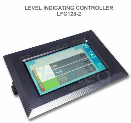
![]() Level Indicating
Level Indicating
Controller LFC128-2
UZANTGVIDILO POR NIVELO-INDIKANTA REGILO LFC128-2
LFC128-2-MN-EN-01 JUN-2020
LFC128-2 Altnivela Ekranregilo
Ĉi tiu dokumento estas aplikata por la sekvaj produktoj
| SKU | LFC128-2 | HW Ver. | 1.0 | FW Ver. | 1.1 |
| Item Kodo | LFC128-2 | Nivel-Indikila Regilo, 4AI/DI, 4DI, 4xRelajso, 1xPulsa Eligo, 2xRS485/ModbusRTU-Sklava Komunikado | |||
Funkcioj Ŝanĝprotokolo
| HW Ver. | FW Ver. | Eldondato | Funkcioj Ŝanĝi |
| 1.0 | 1.1 | JUN-2020 | |
Enkonduko
LFC128-2 estas altnivela ekranregilo. La produkto integras Modbus RTU-interfacon por helpi PLC / SCADA / BMS kaj ajnan IoT-pordon konektiĝi al la monitoro. LFC128-2 havas simplan sed potencan dezajnon kun 4 AI / DI, 4 DI, 4 relajsoj, 1 pulsa pulseligo, 2 RS485-sklavaj ModbusRTU, permesante al ili facile konektiĝi kun pluraj aparatoj. Kun altnivela teknologio, kiu provizas altan stabilecon kaj fidindecon, multajn funkciojn, facilan instaladon kun tuŝekrano kaj amika interfaco, helpas vide monitori la nivelon.
Specifo
| Ciferecaj Enigaĵoj | 04 x Ports, opto-coupler, 4.7 kohms input resisrtance, 5000V rms isolation, Logic 0 (0-1VDC), Logic 1 (5-24VDC), Functions: logic status 0/1 or Pulse counting (32 bit counter with max 4kHz pulse) |
| Analogaj Enigaĵoj | 04 x Ports, select between 0-10VDC input or 0-20mA input, 12 bit Resolution, can be configured as Digital input by DIP switch (max 10VDC input) The AI1 port is a 0-10 VDC / 4-20 mA level sensor connection port |
| Relajsa Eligo | 04 x Ports, electro-mechanical Relays, SPDT, contact rating 24VDC/2A or 250VAC/5A, LED indicators |
| Pulsproduktaĵo | 01 x Ports, open-collector, opto-isolation, max 10mA and 80VDC, On/off control, Pulser (max 2.5Khz, max 65535 Pulses) or PWM (max 2.5Khz) |
| Komunikado | 02 x ModbusRTU-sklavo, RS485, rapideco 9600 aŭ 19200, LED-indikilo |
| Restarigi butonon | For resetting 02 x RS485 Slave port to default setting (9600, None parity, 8 bit) |
| Ekrana tipo | Tuŝekrano |
| Elektroprovizo | 9..36VDC |
| Konsumo | 200mA ĉe 24VDC provizo |
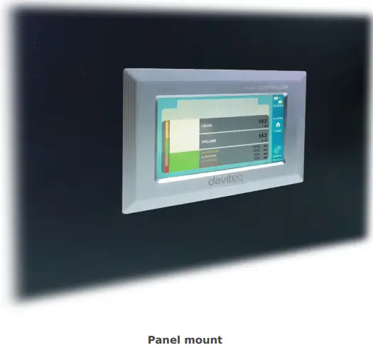
| Munta tipo | Panela monto |
| Fina Bloko | paŝo 5.0mm, tensio 300VAC, dratograndeco 12-24AWG |
| Laboranta temperaturo / humido | 0..60 °C / 95% RH sen kondensado |
| Dimensio | H93xL138xD45 |
| Neta pezo | 390 gramoj |
Produktaj Bildoj


Operacia Principo

5.1 Modbus-komunikado

02 x RS485/ModbusRTU-Slave
Protokolo: Modbus RTU
Adreso: 1 – 247, 0 is the Broadcast address
Baudrapideco: 9600, 19200
Egaleco: neniu, nepara, para
- LED-indikilo de stato:
- Led on: modbus communication OK
- Led blinking: received data but modbus communication incorrect, due to wrong Modbus configuration: address, baudrate
- Led off: LFC128-2 received no data, check the connection
Memmap registriĝas
READ uzas komandon 03, WRITE uzas komandon 16
Defaŭlta agordo:
- Adreso: 1
- Baudrate slave 1: 9600
- Parity slave 1: none
- Baudrate slave 2: 9600
- Parity slave 2: none
| Registro Modbus | Hex adr | # of registers |
Priskribo | Gamo | Defaŭlte | Formato | Proprieto | Komento |
| 0 | 0 | 2 | informoj pri aparato | LFC1 | ŝnuro | Legu | ||
| 8 | 8 | 1 | DI1 DI2: digital status | 0-1 | uint8 | Legu | H_bajto: DI1 L_bajto: DI2 | |
| 9 | 9 | 1 | DI3 DI4: digital status | 0-1 | uint8 | Legu | H_bajto: DI3 L_bajto: DI4 | |
| 10 | A | 1 | AI1 AI2: digital status | 0-1 | uint8 | Legu | H_bajto: AI1 L_bajto: AI2 | |
| 11 | B | 1 | AI3 AI4: digital status | 0-1 | uint8 | Legu | H_bajto: AI3 L_bajto: AI4 | |
| 12 | C | 1 | AI1: analoga valoro | uint16 | Legu | |||
| 13 | D | 1 | AI2: analoga valoro | uint16 | Legu | |||
| 14 | E | 1 | AI3: analoga valoro | uint16 | Legu | |||
| 15 | F | 1 | AI4: analoga valoro | uint16 | Legu | |||
| 16 | 10 | 2 | AI1: skalita valoro | flosi | Legu | |||
| 18 | 12 | 2 | AI2: skalita valoro | flosi | Legu | |||
| 20 | 14 | 2 | AI3: skalita valoro | flosi | Legu | |||
| 22 | 16 | 2 | AI4: skalita valoro | flosi | Legu | |||
| 24 | 18 | 1 | stafetado 1 | 0-1 | uint16 | Legu | ||
| 25 | 19 | 1 | stafetado 2 | 0-1 | uint16 | Legu | ||
| 26 | 1A | 1 | stafetado 3 | 0-1 | uint16 | Legu | ||
| 27 | 1B | 1 | stafetado 4 | 0-1 | uint16 | Legu | ||
| 28 | 1C | 1 | malferma kolektanto ctrl | 0-3 | uint16 | Legu/Skribu | 0: malŝaltita 1: ŝaltita 2: pwm, pulsu kontinue 3: pulsu, kiam sufiĉas pulsnombro, ctrl = 0 | |
| 30 | 1E | 2 | nombrilo DI1 | uint32 | Legu/Skribu | nombrilo skribebla, forviŝebla | ||
| 32 | 20 | 2 | nombrilo DI2 | uint32 | Legu/Skribu | nombrilo skribebla, forviŝebla | ||
| 34 | 22 | 2 | nombrilo DI3 | uint32 | Legu/Skribu | nombrilo skribebla, forviŝebla | ||
| 36 | 24 | 2 | nombrilo DI4 | uint32 | Legu/Skribu | nombrilo skribebla, forviŝebla | ||
| 38 | 26 | 2 | nombrilo AI1 | uint32 | Legu/Skribu | counter writable, erasable, max frequency 10Hz | ||
| 40 | 28 | 2 | nombrilo AI2 | uint32 | Legu/Skribu | counter writable, erasable, max frequency 10Hz | ||
| 42 | 2A | 2 | nombrilo AI3 | uint32 | Legu/Skribu | counter writable, erasable, max frequency 10Hz | ||
| 44 | 2C | 2 | nombrilo AI4 | uint32 | Legu/Skribu | counter writable, erasable, max frequency 10Hz | ||
| 46 | 2E | 2 | DI1: time on | uint32 | Legu/Skribu | sek | ||
| 48 | 30 | 2 | DI2: time on | uint32 | Legu/Skribu | sek | ||
| 50 | 32 | 2 | DI3: time on | uint32 | Legu/Skribu | sek | ||
| 52 | 34 | 2 | DI4: time on | uint32 | Legu/Skribu | sek | ||
| 54 | 36 | 2 | AI1: time on | uint32 | Legu/Skribu | sek | ||
| 56 | 38 | 2 | AI2: time on | uint32 | Legu/Skribu | sek | ||
| 58 | 3A | 2 | AI3: time on | uint32 | Legu/Skribu | sek | ||
| 60 | 3C | 2 | AI4: time on | uint32 | Legu/Skribu | sek | ||
| 62 | 3E | 2 | DI1: time off | uint32 | Legu/Skribu | sek | ||
| 64 | 40 | 2 | DI2: time off | uint32 | Legu/Skribu | sek | ||
| 66 | 42 | 2 | DI3: time off | uint32 | Legu/Skribu | sek | ||
| 68 | 44 | 2 | DI4: time off | uint32 | Legu/Skribu | sek | ||
| 70 | 46 | 2 | AI1: time off | uint32 | Legu/Skribu | sek | ||
| 72 | 48 | 2 | AI2: time off | uint32 | Legu/Skribu | sek | ||
| 74 | 4A | 2 | AI3: time off | uint32 | Legu/Skribu | sek | ||
| 76 | 4C | 2 | AI4: time off | uint32 | Legu/Skribu | sek | ||
| 128 | 80 | 2 | nombrilo DI1 | uint32 | Legu | nombrilo ne povas skribi, forigi | ||
| 130 | 82 | 2 | nombrilo DI2 | uint32 | Legu | nombrilo ne povas skribi, forigi | ||
| 132 | 84 | 2 | nombrilo DI3 | uint32 | Legu | nombrilo ne povas skribi, forigi | ||
| 134 | 86 | 2 | nombrilo DI4 | uint32 | Legu | nombrilo ne povas skribi, forigi | ||
| 136 | 88 | 2 | nombrilo AI1 | uint32 | Legu | nombrilo ne povas skribi, forigi; maksimuma frekvenco 10Hz | ||
| 138 | 8A | 2 | nombrilo AI2 | uint32 | Legu | nombrilo ne povas skribi, forigi; maksimuma frekvenco 10Hz | ||
| 140 | 8C | 2 | nombrilo AI3 | uint32 | Legu | nombrilo ne povas skribi, forigi; maksimuma frekvenco 10Hz | ||
| 142 | 8E | 2 | nombrilo AI4 | uint32 | Legu | nombrilo ne povas skribi, forigi; maksimuma frekvenco 10Hz | ||
| 256 | 100 | 1 | Modbus-adreso sklavo | 1-247 | 1 | uint16 | Legu/Skribu |
|
| 257 | 101 | 1 | modbus baŭdrato sklavo 1 | 0-1 | 0 | uint16 | Legu/Skribu |
0: 9600, 1: 19200 |
| 258 | 102 | 1 | Modbus-pareca sklavo 1 | 0-2 | 0 | uint16 | Legu/Skribu |
0: neniu, 1: nepara, 2: para |
5.2 Restarigi Butonon
When holding the reset button for 4 seconds, LFC 128-2 will reset the default configuration to 02 x RS485 / Modbus
RTU-Slave.
Defaŭlta Modbus RTU-Agordo:
- Adreso: 1
- Baudrapideco: 9600
- Pareco: neniu
5.3 Cifereca Enigo

Specifo:
- 04 channels DI, isolated
- Input Resistance: 4.7 kΏ
- Izolado Voltage: 5000Vrms
- Logic level 0: 0-1V
- Logic level 1: 5-24V
- Funkcio:
- Read logic 0/1
- Pulso-Nombrilo
5.3.1 Legu la logikan staton 0/1
Logika valoro en Modbus-Memormapo: 0-1
Registroj por konservi logikajn valorojn en la Modbus-Memormapo:
- DI1__DI2: digital status: stores the logical state of channel 1 and channel 2.
H_byte: DI1
L_byte: DI2 - DI3__DI4: digital status: store the logical state of channel 3 and channel 4.
H_byte: DI3
L_byte: DI4
5.3.2 Pulskalkulilo
Kalkulilo en Modbus Memormapo, kiam la nombro superas la sojlon, ĝi aŭtomate redonos: 0 4294967295 (32 bitoj)
La registro, kiu konservas la nombrilan valoron en la Modbus-memormapo, ne povas esti forigita:
- Nombrilo DI1: stokas la logikan staton de kanalo 1
- Nombrilo DI2: stokas la logikan staton de kanalo 2
- Counter DI3: store the logic state of channel 3
- Nombrilo DI4: stokas la logikan staton de kanalo 4
La registro, kiu konservas la nombrilan valoron en la Modbus-memormapo, ne povas esti forigita: - None reset counter DI1: stores the logic state of channel 1
- None reset counter DI2: stores the logic state of channel 2
- None reset counter DI3: stores the logic state of channel 3
- None reset counter DI4: stores the logic state of channel 4
Pulse Counter Mode:
Low-speed pulse count less than 10Hz with filter, anti-jamming:
- Set register “counter DI1: filter time” = 500-2000: Channel 1 counts pulses less than 10Hz
- Set register “counter DI2: filter time” = 500-2000: Channel 2 counts pulses less than 10Hz
- Set register “counter DI3: filter time” = 500-2000: Channel 3 counts pulses less than 10Hz
- Set register “counter DI4: filter time” = 500-2000: Channel 4 counts pulses less than 10Hz
- High-speed pulse count with max 2KHz frequency without filter:
- Set register “counter DI1: filter time” = 1: channel 1 counts pulses with Fmax = 2kHz
- Set register “counter DI2: filter time” = 1: channel 2 counts pulses with Fmax = 2kHz
- Set register “counter DI3: filter time” = 1: channel 3 counts pulses with Fmax = 2kHz
- Set register “counter DI4: filter time” = 1: channel 4 counts pulses with Fmax = 2kHz
5.4 Analoga Enigo
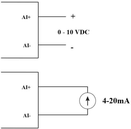
04 AI-kanaloj, sen izolado (AI1 estas 4-20mA / 0-5 VDC / 0-10 VDC nivelsensila enigo)
Uzu DIP-interfacon por agordi analogan eniron: 0-10V, 0-20mA
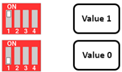
| Valoro | Type of AI |
| 0 | 0-10 V |
| 1 | 0-20 mA |
Eniga tipo:
- Mezuru voltage: 0-10V
- Measure current: 0-20mA
- The configuration for AI reads the same logical state as DI, but it is not isolated with a pulse range of 0-24V
Enira impedanco:
- Mezuru voltage: 320 kΏ
- Measure the current: 499 Ώ
5.4.1 Legu la analogan valoron
Rezolucio 12 bitoj
Ne-Lineareco: 0.1%
Analoga valoro en Modbus-Memormapo: 0-3900
Analoga valorregistro en la Modbus-Memormapo:
- AI1 analog value: store the Analog value of channel 1
- AI2 analog value: stores the Analog value of channel 2
- AI3 analog value: store the Analog value of channel 3
- AI4 analog value: store the Analog value of channel 4
5.4.2 AI-agordo funkcias kiel DI
Neniu izolado
AI Agordu AI por legi la saman logikan staton kiel DI kun pulso amplongitudo de 0-24V
Estas 2 nombrilaj sojloj AIx: logika sojlo 0 kaj nombrilo AIx: logika sojlo 1 en la modbus-tabelo: 0-4095
- Analog Analog value of AI <counter AIx: threshold logic 0: is considered Logic 0 status of AI
- Analog Analog value of AI> counter AIx: threshold logic 1: is considered to be Logic 1 state of AI
- Counter AIx: threshold logic 0 = <Analog value of AI <= counter AIx: threshold logic 1: is considered to be the constant logic state
Logiko Logika statusvaloro de AI en Modbus Memormapa tabelo: 0-1
La registro konservas logikajn valorojn en Modbus Memormapo:
- AI1___AI2: digital status: stores the logical state of channel 1 and channel 2.
H_byte: AI1
L_byte: AI2 - AI3___AI4: digital status: stores the logical state of channel 1 and channel 2.
H_byte: AI3
L_byte: AI4
5.4.3 Pulskalkulilo AI maks. 10Hz
Kalkulilo en Modbus Memormapo, kiam oni aldonas la nombron preter la sojlo, ĝi aŭtomate redonos: 0 4294967295 (32 bitoj)
La registro, kiu konservas la nombrilan valoron en la Modbus-memormapo, ne povas esti forigita:
- Counter AI1: stores the logic state of channel 1
- Counter AI2: save logic state of channel 2
- Counter AI3: save logic state of channel 3
- Counter AI4: save logic state of channel 4
La registro, kiu konservas la nombrilan valoron en la Modbus-memormapo, ne povas esti forigita: - None reset counter AI1: stores the logic state of channel 1
- None reset counter AI2: stores the logic state of channel 2
- None reset counter AI3: stores the logic state of channel 3
- None reset counter AI4: save logic state of channel 4
5.5 Stafeto
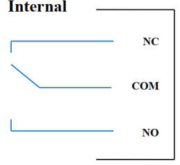
04 channel Relay SPDT NO / NC
Contact rating: 2A / 24VDC, 0.5A / 220VAC
There are status LEDs:
- Led on: Close Contact
- Led off: Open Contact
| Defaŭlta Relajso-Registro | Status of relays when resetting power supplies |
| 3 | Operate according to the Alarm configuration |
Alarma Agordo:
- HIHI : Relay 4 On
- HI : Relay 3 On
- LO : Relay 2 On
- LOLO: Relay 1 On
5.6 Pulsa Eligo

01 isolated open-collector channel
Opto-coupler: Source current Imax = 10mA, Vceo = 80V
Funkcioj: On / Off, pulse generator, PWM
5.6.1 Funkcio Enŝaltita/Malŝaltita
Set the Open-collector register in the Modbus Memory Map table:
- Set Open-collector register: 1 => Pulse Output ON
- Set Open-collector register: 0 => Pulse Output OFF
5.6.2 Pulsgeneratoro
Pulseligo elsendas maksimumon de 65535 pulsoj, kun Fmax 2.5kHz
Agordu la jenajn registrojn en la tabelo Modbus Memormapo:
- Set register “open collector: pulse number”: 0-65535 => Pulse Number = 65535: broadcast 65535 pulses
- Set register “open collector: time cycle”: (0-65535) x0.1ms => Time Cycle = 4: Fmax 2.5kHz
- Set register “open collector: time on”: (0-65535) x0.1ms => Time On: is the logic time 1 of the pulse
- Set the register “open collector ctrl” = 3 => configure the Pulse Output to generate a pulse and start to pulse, generate a sufficient number of pulses in the “open collector: pulse number” register => stop pulse generator and register ” open collector ctrl ”= 0
5.6.3 PWM
Maksimuma frekvenco 2.5kHz
Agordu la jenajn registrojn en la tabelo Modbus Memormapo:
- Set the register “open collector ctrl” = 2 => configure Pulse Output PWM function
- Set register “open collector: time cycle”: (0-65535) x0.1ms => Time Cycle = 4: Fmax 2.5kHz
- Set register “open collector: time on”: (0-65535) x0.1ms => Time On: is the logic time 1 of the pulse
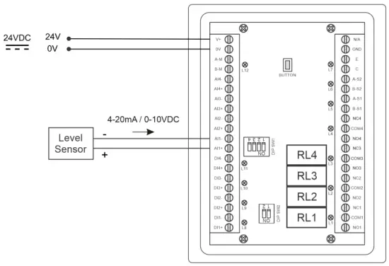
Instalado
6.1 Instala metodo
 6.2 Drataro kun nivelsensilo

Agordo
7.1 Hejma Ekrano

EkRANO: Switch to 2nd screen with more detailed information
ALARMOJ: Show Level Alert
HEJMO: Reiru al Hejma Ekrano
KONFIG. (Default Password: a): Go to Setting Screen
7.2 Agorda ekrano (Defaŭlta pasvorto: a)
7.2.1 Ekrano 1
![daviteq LFC128 2 Advanced Level Display Controller - Home Screen 1] '](https://manuals.plus/wp-content/uploads/2025/08/daviteq-LFC128-2-Advanced-Level-Display-Controller-Home-Screen-1-550x305.png)
ADCoj: Raw signal value of channel AI1
Level (Unit): The level corresponds to the ADC signal after configuration
Decimal Places Level:Decimal number of digits after the dot of Level 0-3 (00000, 1111.1, 222.22, 33.333)
Unit level: level units, 0-3 (0: mm, 1: cm, 2: m, 3: inch)
En 1: Enter the ADC value after putting 4 mA / 0 VDC into AI1 for calibration at 0 level
Skalo 1: The level value displayed corresponds to the value entered in In 1 (usually 0)
En 2: Enter the ADC value after putting 20 mA / 10 VDC into AI1 for calibration at Full level
Skalo 2: The level value displayed corresponds to the value entered in In 2
Span Level: Maximum value of Level (Span Level ≥ Scale 2)
Decimal Places Volume: Decimal number of digits after the dot of Volume 0-3 (00000, 1111.1, 222.22, 33.333)
Unit Volume: units of volume 0-3 (0: lit, 1: cm, 2: m3, 3:%)
7.2.2 Ekrano 2

Level Hi Hi Set point (Unit): High High level of Alarm Level
Level Hi Hi Hys (Unit): High High level hysteresis of Alarm Level
Level Hi Set point (Unit): High level of Alarm Level
Level Hi Hys (Unit): High level hysteresis of Alarm Level
Level Lo Set point (Unit): Low level of Alarm Level
Level Lo Hys (Unit): Low level hysteresis of Alarm Level
Level Lo Lo Set point (Unit): Low Low level of Alarm Level
Level Lo Lo Hys (Unit): Low Low level hysteresis of Alarm Level
Alarma reĝimo: 0: Level, 1: Volume
Span Volume(Unit): Maximum value of the volume
7.2.3 Ekrano 3

Volume Hi Hi Set point (Unit): High High volume of Alarm Volume
Volume Hi Hi Hys (Unit): High High volume hysteresis of Alarm Volume
Volume Hi Set point (Unit): High volume of Alarm Volume
Volume Hi Hys (Unit): High volume hysteresis of Alarm Volume
Volume Lo Set point (Unit): Low volume of Alarm Volume
Volume Lo Hys (Unit): Low volume hysteresis of Alarm Volume
Volume Lo Lo Set point (Unit): Low Low volume of Alarm Volume
Volume Lo Lo Hys (Unit): Low Low volume hysteresis of Alarm Volume
Run Total: Run the total function. 0-1 (0: No 1: Yes)
7.2.4 Ekrano 4

Filling (Unit): Total function: total put into tank
Consumption (Unit): Total function: total consumption of the tank
Decimal Places Total: Decimal number of parameters Filling, Consumption, NRT Filling, NRT Consumption on display page (not the setting page)
Delta Total (Unit): Hysteresis level of the total function
Modbus-adreso: Modbus address of LFC128-2, 1-247
Modbus Baurate S1: 0-1 (0 : 9600 , 1 : 19200)
Modbus Parity S1: 0-2 (0: none, 1: odd, 2: even)
Modbus Baurate S2: 0-1 (0 : 9600 , 1 : 19200)
Modbus Parity S2: 0-2 (0: none, 1: odd, 2: even)
Num of Points: Number of points in the table to convert from level to volume, 1-166
7.2.5 Ekrano 5

Point 1 Level (Level Unit): Level at Point 1
Point 1 Volume (Volume Unit): The corresponding volume at Point 1
Point 166 Level (Level Unit): Fuel level at Point 166
Point 166 Volume (Volume Unit): The corresponding volume at Point 166
7.2.6 Ekrano 6

Pasvorto: Password to enter the Setting page, 8 ASCII characters
Tank Name: Tank name displayed on the main screen
Solvado de problemoj
| Ne. | Fenomenoj | Kialo | Solvoj |
| 1 | Modbus malsukcesis komuniki | Modbus LED Status: LED is off: received no data LED is blinking: the Modbus configuration is not the correct | Kontrolu la konekton Kontrolu la Modbus-agordon: Adreso, Baud-rapideco, Pareco |
| 2 | Templimo Modbus | Bruo aperas sur la linio | Agordu baudrapidecon 9600 kaj uzu torditan parkablon kun kontraŭ-ĝena protekto |
| 3 | Sensilo Malkonektita | Sensilo kaj LFC128 perdis konekton | Checking connection Check sensor type (LFC128-2 only connects to 0-10VDC / 4- 20mA analog sensor type) Check the switch to see if it is turned on correctly Check that the sensor connector is correct AI1 |
| 4 | Lineariga tabeleraro | Eraro de konvertabelo de nivelo al volumeno | Kontrolu la agordon de la konvertabelo de nivelo al volumeno |
Subtenaj kontaktoj
Fabrikisto
Daviteq Technologies Inc
No.11 Street 2G, Nam Hung Vuong Res., An Lac Ward, Binh Tan Dist., Ho-Ĉi-Min-urbo, Vjetnamio.
Tel: +84-28-6268.2523/4 (ext.122)
Retpoŝto: info@daviteq.com
www.daviteq.com
Dokumentoj/Rimedoj
 |
daviteq LFC128-2 Altnivela Ekranregilo [pdf] Instrukcia Manlibro LFC128-2, LFC128-2 Altnivela Ekranregilo, Altnivela Ekranregilo, Nivela Ekranregilo, Ekranregilo |