![]() د کچې ښودنه
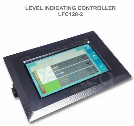
د کچې ښودنه
کنټرولر LFC128-2
د کچې ښودلو کنټرولر LFC128-2 لپاره د کارونکي لارښود
د LFC128-2-MN-EN-01 جون-2020 لپاره تفتیش وسپارئ، موږ به په 24 ساعتونو کې له تاسو سره اړیکه ونیسو.
LFC128-2 د پرمختللې کچې ښودنې کنټرولر
دا سند د لاندې محصولاتو لپاره پلي کیږي
| SKU | LFC128-2 | HW Ver. | 1.0 | FW Ver. | 1.1 |
| د توکي کوډ | LFC128-2 | د کچې ښودلو کنټرولر، 4AI/DI، 4DI، 4xRelay، 1xPulse Output، 2 x RS485/ModbusRTU-Slave Communication | |||
د دندو د بدلون لاګ
| HW Ver. | FW Ver. | د خپریدو نیټه | افعال بدلون |
| 1.0 | 1.1 | جون - ۲۰۲۰ | |
پیژندنه
LFC128-2 د پرمختللې کچې ښودنې کنټرولر دی. دا محصول د PLC / SCADA / BMS سره مرسته کولو لپاره د Modbus RTU انٹرفیس مدغم کوي او هر IoT پورټ کولی شي د مانیټر سره وصل شي. LFC128-2 یو ساده مګر پیاوړی ډیزاین لري چې 4 AI / DI، 4 DI، 4 Relays، 1 Pulse Pulse Output، 2 RS485 Slave ModbusRTU لري چې دوی ته اجازه ورکوي چې په اسانۍ سره د ډیری وسیلو سره وصل شي. د پرمختللي ټیکنالوژۍ سره چې لوړ ثبات او اعتبار چمتو کوي، ډیری دندې، د ټچ سکرین سره اسانه نصب او دوستانه انٹرفیس د لید لید څارنه کې مرسته کوي.
مشخصات
| ډیجیټل داخلې | 04 x پورټونه، آپټو-کوپلر، 4.7 kohms ان پټ مقاومت، 5000V rms جلا کول، منطق 0 (0-1VDC)، منطق 1 (5-24VDC)، دندې: د منطق حالت 0/1 یا د نبض شمیرنه (د اعظمي 4kHz نبض سره 32 بټ کاونټر) |
| انلاګ معلومات | 04 x پورټونه، د 0-10VDC ان پټ یا 0-20mA ان پټ ترمنځ غوره کړئ، 12 بټ ریزولوشن، د DIP سویچ لخوا د ډیجیټل ان پټ په توګه تنظیم کیدی شي ( اعظمي 10VDC ان پټ) د AI1 پورټ د 0-10 VDC / 4-20 mA کچې سینسر اتصال پورټ دی |
| د ریلیز محصول | 04 x پورټونه، الکترو میخانیکي ریلونه، SPDT، د تماس درجه 24VDC/2A یا 250VAC/5A، د LED شاخصونه |
| د نبض وتنه | 01 x پورټونه، خلاص راټولونکی، آپټو-ازولیشن، اعظمي 10mA او 80VDC، آن/آف کنټرول، پلسر ( اعظمي 2.5Khz، اعظمي 65535 نبضونه) یا PWM ( اعظمي 2.5Khz) |
| اړیکه | 02 x ModbusRTU-غلام، RS485، سرعت 9600 یا 19200، د LED شاخص |
| د بیا تنظیم کولو تڼۍ | د 02 x RS485 سلیو پورټ د ډیفالټ ترتیب ته د بیا تنظیمولو لپاره (9600، هیڅ برابري نه، 8 بټ) |
| د سکرین ډول | ټچ سکرین |
| د بریښنا رسول | 9..36VDC |
| مصرف | ۲۰۰mA @ ۲۴VDC عرضه |
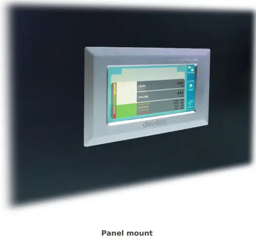
| د نصب کولو ډول | د پینل نصبول |
| ټرمینل بلاک | پچ ۵.۰ ملي متره، درجه بندي ۳۰۰VAC، د تار اندازه ۱۲-۲۴AWG |
| د حرارت درجه / رطوبت | 0..60 درجو سانتي ګراد / 95% RH غیر کنډنسنګ |
| ابعاد | H93xW138xD45 |
| خالص وزن | 390 ګرامه |
د محصول انځورونه


د عملیاتو اصول

5.1 موډبس ارتباط

02 x RS485/ModbusRTU-غلام
پروتوکول: Modbus RTU
پته: ۱ - ۲۴۷، ۰ د خپرونې پته ده
د بوډ نرخ: ۷، ۹
برابري: هیڅ نه، عجیب، مساوي
- د حالت شاخص LED:
- په مشرۍ: د موډبس اړیکه سمه ده
- د LED ځلیدل: معلومات ترلاسه شوي مګر د موډبس اړیکه غلطه ده، د غلط موډبس ترتیب له امله: پته، باډریټ
- لیډ آف: LFC128-2 هیڅ معلومات ترلاسه نه کړل، پیوستون وګورئ
د میممپ راجسترونه
READ د 03 قومانده کاروي، WRITE د 16 قومانده کاروي
ډیفالټ ترتیب:
- پته: 1
- د بوډریټ غلام ۱: ۹۶۰۰
- د برابرۍ غلام ۱: هیڅ نه
- د بوډریټ غلام ۱: ۹۶۰۰
- د برابرۍ غلام ۱: هیڅ نه
| د Modbus ثبت | هیکس اډر | د راجسترونو شمېر |
تفصیل | رینج | ډیفالټ | بڼه | ملکیت | تبصره |
| 0 | 0 | 2 | د وسیلې معلومات | LFC1 | تار | لوستل | ||
| 8 | 8 | 1 | DI1 DI2: ډیجیټل حالت | 0-1 | uint8 | لوستل | H_byte: DI1 L_byte: DI2 | |
| 9 | 9 | 1 | DI3 DI4: ډیجیټل حالت | 0-1 | uint8 | لوستل | H_byte: DI3 L_byte: DI4 | |
| 10 | A | 1 | AI 1 AI2: ډیجیټل حالت | 0-1 | uint8 | لوستل | H_byte: AI1 L_byte: AI2 | |
| 11 | B | 1 | AI 3 AI4: ډیجیټل حالت | 0-1 | uint8 | لوستل | H_byte: AI3 L_byte: AI4 | |
| 12 | C | 1 | AI1: انلاګ ارزښت | uint16 | لوستل | |||
| 13 | D | 1 | AI2: انلاګ ارزښت | uint16 | لوستل | |||
| 14 | E | 1 | AI3: انلاګ ارزښت | uint16 | لوستل | |||
| 15 | F | 1 | AI4: انلاګ ارزښت | uint16 | لوستل | |||
| 16 | 10 | 2 | AI1: اندازه شوی ارزښت | تیریدل | لوستل | |||
| 18 | 12 | 2 | AI2: اندازه شوی ارزښت | تیریدل | لوستل | |||
| 20 | 14 | 2 | AI3: اندازه شوی ارزښت | تیریدل | لوستل | |||
| 22 | 16 | 2 | AI4: اندازه شوی ارزښت | تیریدل | لوستل | |||
| 24 | 18 | 1 | ریلی 1 | 0-1 | uint16 | لوستل | ||
| 25 | 19 | 1 | ریلی 2 | 0-1 | uint16 | لوستل | ||
| 26 | 1A | 1 | ریلی 3 | 0-1 | uint16 | لوستل | ||
| 27 | 1B | 1 | ریلی 4 | 0-1 | uint16 | لوستل | ||
| 28 | 1C | 1 | خلاص راټولونکی ctrl | 0-3 | uint16 | لوستل / لیکل | ۰: بند ۱: په ۲: pwm، په دوامداره توګه نبض ۳: نبض، کله چې د نبض شمیره کافي وي، ctrl = ۰ | |
| 30 | 1E | 2 | د DI1 کاونټر | uint32 | لوستل / لیکل | د مقایسي لیکلو وړ، د پاکولو وړ | ||
| 32 | 20 | 2 | د DI2 کاونټر | uint32 | لوستل / لیکل | د مقایسي لیکلو وړ، د پاکولو وړ | ||
| 34 | 22 | 2 | د DI3 کاونټر | uint32 | لوستل / لیکل | د مقایسي لیکلو وړ، د پاکولو وړ | ||
| 36 | 24 | 2 | د DI4 کاونټر | uint32 | لوستل / لیکل | د مقایسي لیکلو وړ، د پاکولو وړ | ||
| 38 | 26 | 2 | د AI1 ضد | uint32 | لوستل / لیکل | د مقایسي لیکلو وړ، د پاکولو وړ، اعظمي فریکونسي 10Hz | ||
| 40 | 28 | 2 | د AI2 ضد | uint32 | لوستل / لیکل | د مقایسي لیکلو وړ، د پاکولو وړ، اعظمي فریکونسي 10Hz | ||
| 42 | 2A | 2 | د AI3 ضد | uint32 | لوستل / لیکل | د مقایسي لیکلو وړ، د پاکولو وړ، اعظمي فریکونسي 10Hz | ||
| 44 | 2C | 2 | د AI4 ضد | uint32 | لوستل / لیکل | د مقایسي لیکلو وړ، د پاکولو وړ، اعظمي فریکونسي 10Hz | ||
| 46 | 2E | 2 | DI1: وخت پیل شو | uint32 | لوستل / لیکل | ثانیه | ||
| 48 | 30 | 2 | DI2: وخت پیل شو | uint32 | لوستل / لیکل | ثانیه | ||
| 50 | 32 | 2 | DI3: وخت پیل شو | uint32 | لوستل / لیکل | ثانیه | ||
| 52 | 34 | 2 | DI4: وخت پیل شو | uint32 | لوستل / لیکل | ثانیه | ||
| 54 | 36 | 2 | AI1: وخت پیل شو | uint32 | لوستل / لیکل | ثانیه | ||
| 56 | 38 | 2 | AI2: وخت پیل شو | uint32 | لوستل / لیکل | ثانیه | ||
| 58 | 3A | 2 | AI3: وخت پیل شو | uint32 | لوستل / لیکل | ثانیه | ||
| 60 | 3C | 2 | AI4: وخت پیل شو | uint32 | لوستل / لیکل | ثانیه | ||
| 62 | 3E | 2 | DI1: رخصتي | uint32 | لوستل / لیکل | ثانیه | ||
| 64 | 40 | 2 | DI2: رخصتي | uint32 | لوستل / لیکل | ثانیه | ||
| 66 | 42 | 2 | DI3: رخصتي | uint32 | لوستل / لیکل | ثانیه | ||
| 68 | 44 | 2 | DI4: رخصتي | uint32 | لوستل / لیکل | ثانیه | ||
| 70 | 46 | 2 | AI1: د رخصتۍ وخت | uint32 | لوستل / لیکل | ثانیه | ||
| 72 | 48 | 2 | AI2: د رخصتۍ وخت | uint32 | لوستل / لیکل | ثانیه | ||
| 74 | 4A | 2 | AI3: د رخصتۍ وخت | uint32 | لوستل / لیکل | ثانیه | ||
| 76 | 4C | 2 | AI4: د رخصتۍ وخت | uint32 | لوستل / لیکل | ثانیه | ||
| 128 | 80 | 2 | د DI1 کاونټر | uint32 | لوستل | کاونټر نشي لیکلی، پاکولی شي | ||
| 130 | 82 | 2 | د DI2 کاونټر | uint32 | لوستل | کاونټر نشي لیکلی، پاکولی شي | ||
| 132 | 84 | 2 | د DI3 کاونټر | uint32 | لوستل | کاونټر نشي لیکلی، پاکولی شي | ||
| 134 | 86 | 2 | د DI4 کاونټر | uint32 | لوستل | کاونټر نشي لیکلی، پاکولی شي | ||
| 136 | 88 | 2 | د AI1 ضد | uint32 | لوستل | کاونټر نشي لیکلی، پاکولی شي؛ اعظمي فریکونسي 10Hz | ||
| 138 | 8A | 2 | د AI2 ضد | uint32 | لوستل | کاونټر نشي لیکلی، پاکولی شي؛ اعظمي فریکونسي 10Hz | ||
| 140 | 8C | 2 | د AI3 ضد | uint32 | لوستل | کاونټر نشي لیکلی، پاکولی شي؛ اعظمي فریکونسي 10Hz | ||
| 142 | 8E | 2 | د AI4 ضد | uint32 | لوستل | کاونټر نشي لیکلی، پاکولی شي؛ اعظمي فریکونسي 10Hz | ||
| 256 | 100 | 1 | د موډبس پته غلام | 1-247 | 1 | uint16 | لوستل / لیکل |
|
| 257 | 101 | 1 | موډبس باډریټ غلام ۱ | 0-1 | 0 | uint16 | لوستل / لیکل |
0: 9600، 1: 19200 |
| 258 | 102 | 1 | د موډبس پارټي غلام ۱ | 0-2 | 0 | uint16 | لوستل / لیکل |
0: هیڅ نه، 1: عجیب، 2: حتی |
5.2 د ری سیٹ تڼۍ
کله چې د ری سیٹ تڼۍ د 4 ثانیو لپاره ونیسئ، LFC 128-2 به د ډیفالټ ترتیب 02 x RS485 / Modbus ته بیا تنظیم کړي.
RTU-غلام.
د موډبس RTU ډیفالټ ترتیب:
- پته: 1
- د بوډ نرخ: 9600
- برابري: هیڅ نه
5.3 ډیجیټل ننوت

مشخصات:
- 04 چینلونه DI، جلا شوی
- د ننوتلو مقاومت: 4.7 kΏ
- انزوا والیومtage: 5000Vrms
- د منطق کچه 0: 0-1V
- د منطق کچه 1: 5-24V
- دنده:
- منطق 0/1 ولولئ
- د نبض کاونټر
۵.۳.۱ منطقي حالت ۰/۱ ولولئ
د موډبس حافظې نقشې کې منطقي ارزښت: 0-1
د موډبس حافظې نقشې کې د منطقي ارزښتونو ذخیره کولو لپاره راجسترونه:
- DI1__DI2: ډیجیټل حالت: د چینل ۱ او چینل ۲ منطقي حالت ذخیره کوي.
H_byte: DI1
L_byte: DI2 - DI3__DI4: ډیجیټل حالت: د چینل 3 او چینل 4 منطقي حالت ذخیره کړئ.
H_byte: DI3
L_byte: DI4
۵.۳.۲ د نبض شمېرونکی
د موډبس حافظې نقشې کې د کاونټر ارزښت، کله چې شمیره اضافه شي نو له حد څخه تیریږي، دا به په اتوماتيک ډول بیرته راشي: 0 4294967295 (32 بټونه)
هغه راجستر چې د موډبس حافظې نقشې کې د کاونټر ارزښت ذخیره کوي له منځه وړل کیدی نشي:
- کاونټر DI1: د چینل ۱ منطقي حالت ذخیره کوي
- کاونټر DI2: د چینل ۱ منطقي حالت ذخیره کوي
- کاونټر DI3: د چینل 3 منطقي حالت ذخیره کړئ
- کاونټر DI4: د چینل ۱ منطقي حالت ذخیره کوي
هغه راجستر چې د موډبس حافظې نقشې کې د کاونټر ارزښت ذخیره کوي له منځه وړل کیدی نشي: - هیڅ نه بیا تنظیم شوی کاونټر DI1: د چینل 1 منطقي حالت ذخیره کوي
- هیڅ نه بیا تنظیم شوی کاونټر DI2: د چینل 2 منطقي حالت ذخیره کوي
- هیڅ نه بیا تنظیم شوی کاونټر DI3: د چینل 3 منطقي حالت ذخیره کوي
- هیڅ نه بیا تنظیم شوی کاونټر DI4: د چینل 4 منطقي حالت ذخیره کوي
د نبض ضد حالت:
د فلټر سره د ټیټ سرعت نبض شمیر له 10Hz څخه کم، د جامدو ضد:
- د راجستر تنظیم کړئ "کاونټر DI1: د فلټر وخت" = 500-2000: چینل 1 د 10Hz څخه کم نبضونه حسابوي
- د راجستر تنظیم کړئ "کاونټر DI2: د فلټر وخت" = 500-2000: چینل 2 د 10Hz څخه کم نبضونه حسابوي
- د راجستر تنظیم کړئ "کاونټر DI3: د فلټر وخت" = 500-2000: چینل 3 د 10Hz څخه کم نبضونه حسابوي
- د راجستر تنظیم کړئ "کاونټر DI4: د فلټر وخت" = 500-2000: چینل 4 د 10Hz څخه کم نبضونه حسابوي
- د لوړ سرعت نبض شمېرنه د اعظمي 2KHz فریکونسۍ سره پرته له فلټر څخه:
- راجستر "کاونټر DI1: د فلټر وخت" تنظیم کړئ = 1: چینل 1 د Fmax = 2kHz سره نبضونه حسابوي
- راجستر "کاونټر DI2: د فلټر وخت" تنظیم کړئ = 1: چینل 2 د Fmax = 2kHz سره نبضونه حسابوي
- راجستر "کاونټر DI3: د فلټر وخت" تنظیم کړئ = 1: چینل 3 د Fmax = 2kHz سره نبضونه حسابوي
- راجستر "کاونټر DI4: د فلټر وخت" تنظیم کړئ = 1: چینل 4 د Fmax = 2kHz سره نبضونه حسابوي
5.4 انلاګ ان پټ
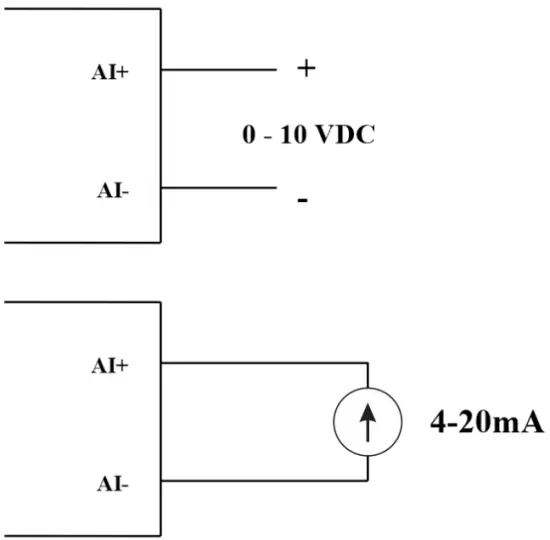
04 AI چینلونه، هیڅ جلاوالی نشته (AI1 د 4-20mA / 0-5 VDC / 0-10 VDC کچې سینسر ان پټ دی)
د انلاګ ان پټ تنظیمولو لپاره DIP SW وکاروئ: 0-10V، 0-20mA
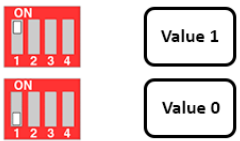
| ارزښت | د مصنوعي ذهانت ډول |
| 0 | 0-10 V |
| 1 | 0-20 mA |
د ننوتلو ډول:
- اندازه ولولئtage: 0-10V
- د اوسني اندازه کول: 0-20mA
- د AI ترتیب د DI په څیر ورته منطقي حالت لوستلی شي، مګر دا د 0-24V د نبض رینج سره جلا شوی نه دی.
د ننوتلو خنډ:
- اندازه ولولئtage: ۳۲۰ کیلو ګرامه
- د جریان اندازه کول: 499 Ώ
۵.۴.۱ د انالوګ ارزښت ولولئ
د 12 ټوټې حل کړئ
غیر خطي: ۰.۱٪
د موډبس حافظې نقشې کې انلاګ ارزښت: 0-3900
د موډبس حافظې نقشې کې د انلاګ ارزښت راجستر:
- د AI1 انلاګ ارزښت: د چینل ۱ انلاګ ارزښت ذخیره کړئ
- د AI2 انلاګ ارزښت: د چینل 2 انلاګ ارزښت ذخیره کوي
- د AI3 انلاګ ارزښت: د چینل ۱ انلاګ ارزښت ذخیره کړئ
- د AI4 انلاګ ارزښت: د چینل ۱ انلاګ ارزښت ذخیره کړئ
۵.۴.۲ د AI ترتیب د DI په توګه کار کوي
نه انزوا
AI د نبض سره د DI په څیر ورته منطقي حالت لوستلو لپاره AI تنظیم کړئ ampد ۰-۲۴ وولټ څخه رڼا
په موډبس جدول کې دوه کاونټر حد AIx: منطق حد 2 او کاونټر AIx: حد منطق 0 شتون لري: 1-0
- د AI انالوګ ارزښت
- د AI> کاونټر AI انالوګ ارزښت x: د حد منطق 1: د AI منطق 1 حالت ګڼل کیږي
- د کاونټر AIx: د حد منطق 0 =
د موډبس حافظې نقشې جدول کې د AI منطق منطقي حالت ارزښت: 0-1
راجستر منطقي ارزښتونه په موډبس حافظې نقشه کې ذخیره کوي:
- AI1___AI2: ډیجیټل حالت: د چینل ۱ او چینل ۲ منطقي حالت ذخیره کوي.
H_byte: AI1
L_byte: AI2 - AI3___AI4: ډیجیټل حالت: د چینل ۱ او چینل ۲ منطقي حالت ذخیره کوي.
H_byte: AI3
L_byte: AI4
۵.۴.۳ د نبض کاونټر AI اعظمي ۱۰ هرټز
د موډبس حافظې نقشې کې د کاونټر ارزښت، کله چې د حد څخه هاخوا شمیره اضافه شي، نو دا به په اتوماتيک ډول بیرته راشي: 0 4294967295 (32 بټونه)
هغه راجستر چې د موډبس حافظې نقشې کې د کاونټر ارزښت ذخیره کوي له منځه وړل کیدی نشي:
- کاونټر AI1: د چینل ۱ منطقي حالت ذخیره کوي
- کاونټر AI2: د چینل 2 منطقي حالت خوندي کړئ
- کاونټر AI3: د چینل 3 منطقي حالت خوندي کړئ
- کاونټر AI4: د چینل 4 منطقي حالت خوندي کړئ
هغه راجستر چې د موډبس حافظې نقشې کې د کاونټر ارزښت ذخیره کوي له منځه وړل کیدی نشي: - هیڅ نه د کاونټر AI1 بیا تنظیم کړئ: د چینل 1 منطقي حالت ذخیره کوي
- هیڅ نه د کاونټر AI2 بیا تنظیم کړئ: د چینل 2 منطقي حالت ذخیره کوي
- هیڅ نه د کاونټر AI3 بیا تنظیم کړئ: د چینل 3 منطقي حالت ذخیره کوي
- هیڅ نه د AI4 کاونټر بیا تنظیم کړئ: د چینل 4 منطقي حالت خوندي کړئ
5.5 ریل
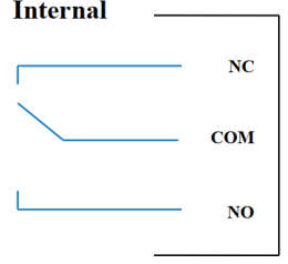
د 04 چینل ریلے SPDT NO / NC
د اړیکو درجه بندي: 2A / 24VDC، 0.5A / 220VAC
د حالت LEDs شتون لري:
- په مشرۍ کې: نږدې اړیکه
- لیډ آف: اړیکه پرانیزئ
| د ډیفالټ ریلې راجستر | د بریښنا رسولو بیا تنظیمولو پر مهال د ریلونو حالت |
| 3 | د الارم ترتیب سره سم کار وکړئ |
د الارم ترتیب:
- HIHI: ریلے ۴ آن
- HI: ریلے ۳ آن
- LO: ریلے ۲ آن
- لولو: ریلے ۱ آن
5.6 د نبض محصول

01 جلا شوی خلاص راټولونکی چینل
آپټو-کوپلر: د سرچینې جریان Imax = 10mA، Vceo = 80V
دندې: چالان / بند، د نبض جنراتور، PWM
۵.۶.۱ د فعالولو/بندولو دنده
د موډبس حافظې نقشې جدول کې د خلاص راټولونکي راجستر تنظیم کړئ:
- د خلاص راټولونکي راجستر تنظیم کړئ: ۱ => د نبض محصول فعال کړئ
- د خلاص راټولونکي راجستر تنظیم کړئ: 0 => د نبض محصول بند کړئ
۵.۶.۲ د نبض جنراتور
د نبض تولید اعظمي حد 65535 نبضونه لیږدوي، د Fmax 2.5kHz سره
د موډبس حافظې نقشې جدول کې لاندې راجسترونه تنظیم کړئ:
- د راجستر تنظیم کړئ "خلاص راټولونکی: د نبض شمیره": 0-65535 => د نبض شمیره = 65535: د 65535 نبضونو خپرول
- د راجستر تنظیم کړئ "خلاص راټولونکی: د وخت دوره": (0-65535) x0.1ms => د وخت دوره = 4: Fmax 2.5kHz
- د راجستر تنظیم کړئ "خلاص راټولونکی: وخت فعال دی": (0-65535) x0.1ms => وخت فعال دی: د نبض منطقي وخت 1 دی
- د "خلاص راټولونکي ctrl" راجستر تنظیم کړئ = 3 => د نبض تولید او نبض پیل کولو لپاره د نبض محصول تنظیم کړئ، په "خلاص راټولونکي: د نبض شمیره" کې کافي شمیر نبضونه تولید کړئ راجستر => د نبض جنراتور ودروئ او راجستر کړئ "خلاص راټولونکي ctrl" = 0
5.6.3 PWM
اعظمي فریکونسي 2.5kHz
د موډبس حافظې نقشې جدول کې لاندې راجسترونه تنظیم کړئ:
- د راجستر "خلاص راټولونکی ctrl" = 2 => د نبض محصول PWM فعالیت تنظیم کړئ
- د راجستر تنظیم کړئ "خلاص راټولونکی: د وخت دوره": (0-65535) x0.1ms => د وخت دوره = 4: Fmax 2.5kHz
- د راجستر تنظیم کړئ "خلاص راټولونکی: وخت فعال دی": (0-65535) x0.1ms => وخت فعال دی: د نبض منطقي وخت 1 دی
نصب کول
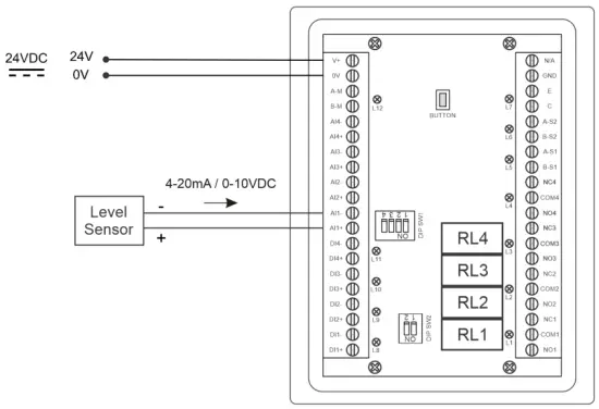
6.1 د نصبولو طریقه
 ۶.۲ د لیول سینسر سره تارونه

ترتیب
7.1 کور سکرین

سکرین: د نورو تفصيلي معلوماتو سره دوهم سکرین ته لاړ شئ
خطرونه: د کچې خبرتیا وښایاست
کور: کور سکرین ته بیرته راشئ
CONFIG. (ډیفالټ پاسورډ: a): د تنظیم کولو سکرین ته لاړ شئ
۷.۲ د تنظیم کولو سکرین (ډیفالټ پټنوم: a)
۲ سکرین ۱
![daviteq LFC128 2 د پرمختللې کچې ښودنې کنټرولر - د کور سکرین 1] '](https://manuals.plus/wp-content/uploads/2025/08/daviteq-LFC128-2-Advanced-Level-Display-Controller-Home-Screen-1-550x305.png)
ADCs: د چینل AI1 خام سیګنال ارزښت
کچه (یونټ): کچه د ترتیب وروسته د ADC سیګنال سره مطابقت لري
د لسیزو ځایونو کچه: د 0-3 کچې د نقطې وروسته د عددونو لسیزه شمیره (00000، 1111.1، 222.22، 33.333)
د واحد کچه: د کچې واحدونه، 0-3 (0: mm، 1: cm، 2: m، 3: انچه)
په 1 کې: د 0 کچې د کیلیبریشن لپاره په AI1 کې د 4 mA / 0 VDC اچولو وروسته د ADC ارزښت دننه کړئ.
پیمانه 1: ښودل شوی د کچې ارزښت په ان 1 کې داخل شوي ارزښت سره مطابقت لري (معمولا 0)
په 2 کې: د بشپړې کچې کیلیبریشن لپاره په AI1 کې د 20 mA / 10 VDC اچولو وروسته د ADC ارزښت دننه کړئ.
پیمانه 2: ښودل شوی د کچې ارزښت په ان 2 کې داخل شوي ارزښت سره مطابقت لري
د اوږدوالي کچه: د کچې اعظمي ارزښت (د مودې کچه ≥ پیمانه 2)
د لسیزو ځایونو حجم: د ټوک ۰-۳ (۰۰۰۰۰، ۱۱۱۱.۱، ۲۲۲.۲۲، ۳۳.۳۳۳) د نقطې وروسته د عددونو لسیزه شمېره
د واحد حجم: د ۰-۳ حجم واحدونه (۰: لیټ، ۱: سانتي متره، ۲: متر۳، ۳:٪)
۲ سکرین ۱

کچه لوړ لوړ د سیټ نقطه (یونټ): د الارم لوړه کچه
کچه سلام سلام (یونټ): د الارم کچې لوړ لوړ هیسټریسیس
د لوړې کچې سیټ نقطه (یونټ): د الارم کچه لوړه کچه
د های هایس کچه (یونټ): د الارم کچې لوړ هسټریسیس
د کچې ټیټ سیټ نقطه (یونټ): د الارم کچه ټیټه کچه
د لو هایس کچه (یونټ): د الارم کچې ټیټې کچې هیسټریسیس
د لو لو سیټ نقطه (یونټ): د الارم کچه ټیټه کچه
د لو لو هایس کچه (یونټ): د الارم کچې ټیټ ټیټ هیسټریسیس
د الارم حالت: ۰: کچه، ۱: حجم
د اوږدوالي حجم (یونټ): د حجم اعظمي ارزښت
۲ سکرین ۱

حجم ها ها د سیټ نقطه (یونټ): د الارم لوړ حجم
ټوک سلام سلام (یونټ): د الارم حجم لوړ لوړ حجم هیسټریسیس
د حجم لوړ سیټ نقطه (یونټ): د الارم لوړ حجم
د سلام هایس ټوک (یونټ): د الارم حجم لوړ حجم هیسټریسیس
د حجم د کموالي د ټاکلو نقطه (یونټ): د الارم حجم ټیټ
حجم لو هایس (یونټ): د الارم حجم ټیټ حجم هیسټریسیس
د حجم کموالي د سیټ نقطه (یونټ): د الارم حجم ټیټ
حجم لو لو هایس (یونټ): د الارم حجم ټیټ ټیټ حجم هیسټریسیس
د منډو ټولټال: ټول فعالیت پرمخ بوځئ. 0-1 (0: نه 1: هو)
۲ سکرین ۱

ډکول (یونټ): ټول فعالیت: ټول په ټانک کې اچول شوی
مصرف (واحد): ټول فعالیت: د ټانک ټول مصرف
د لسیزو ځایونو ټولټال: د پارامترونو لسیزه شمیره ډکول، مصرف، د NRT ډکول، د ښودلو پاڼې کې د NRT مصرف (نه د ترتیب پاڼې)
ډیلټا ټولټال (یونټ): د ټول فعالیت د هیسټریسیس کچه
د موډبس پته: د LFC128-2، 1-247 د موډبس پته
موډبس بورات S1: ۰-۱ (۰: ۹۶۰۰، ۱: ۱۹۲۰۰)
موډبس پیریټي S1: ۰-۲ (۰: هیڅ نه، ۱: طاق، ۲: جفت)
موډبس بورات S2: ۰-۱ (۰: ۹۶۰۰، ۱: ۱۹۲۰۰)
موډبس پیریټي S2: ۰-۲ (۰: هیڅ نه، ۱: طاق، ۲: جفت)
د نمرو شمېر: په جدول کې د هغو ټکو شمیر چې له کچې څخه حجم ته یې بدلول کیږي، ۱-۱۶۶
۲ سکرین ۱

لومړۍ درجه (د کچې واحد): په لومړي مقام کې کچه
لومړی ټکی حجم (د حجم واحد): په لومړي ټکي کې اړونده حجم
نقطه ۱۶۶ کچه (د کچې واحد): د سونګ توکو کچه په ۱۶۶ نقطه کې
لومړی ټکی حجم (د حجم واحد): په لومړي ټکي کې اړونده حجم
۲ سکرین ۱

رمز: د تنظیم پاڼې ته د ننوتلو لپاره پټنوم، ۸ ASCII حروف
د ټانک نوم: د ټانک نوم په اصلي سکرین کې ښودل شوی
د ستونزو حل کول
| نه. | پدیده | دلیل | د حل لارې |
| 1 | موډبس په اړیکه کې پاتې راغی | د موډبس LED حالت: LED بند دی: هیڅ معلومات نه دي ترلاسه شوي LED ځلیږي: د موډبس ترتیب سم نه دی | پیوستون وګورئ د موډبس ترتیب وګورئ: پته، د بوډ کچه، برابري |
| 2 | د موډبس وخت پای | په لیکه کې شور ښکاري | د بوډریټ ۹۶۰۰ تنظیم کړئ او د جام ضد محافظت سره د ټویسټ شوي جوړه کیبل وکاروئ |
| 3 | سینسر قطع شوی | د سینسر او LFC128 اړیکه له لاسه ورکړه | د اتصال چک کول د سینسر ډول چیک کړئ (LFC128-2 یوازې د 0-10VDC / 4- 20mA انلاګ سینسر ډول سره وصل کیږي) سویچ چیک کړئ ترڅو وګورئ چې دا په سمه توګه چالان شوی که نه چیک کړئ چې د سینسر نښلونکی سم دی AI1 |
| 4 | د خطي کولو جدول تېروتنه | د کچې څخه حجم ته د تبادلې جدول تېروتنه | د کچې څخه تر حجم پورې د تبادلې جدول ترتیب وګورئ. |
د تماسونو ملاتړ
جوړونکی
Daviteq Technologies Inc
No.11 Street 2G, Nam Hung Vuong Res., An Lac Ward, Binh Tan Dist., Ho Chi Minh City, Vietnam.
Tel: +84-28-6268.2523/4 (ext.122)
بریښنالیک: info@daviteq.com
www.daviteq.com
اسناد / سرچینې
 |
daviteq LFC128-2 د پرمختللې کچې ښودنې کنټرولر [pdf] د لارښوونې لارښود LFC128-2، LFC128-2 د پرمختللې کچې ښودنې کنټرولر، د پرمختللې کچې ښودنې کنټرولر، د کچې ښودنې کنټرولر، د ښودنې کنټرولر |