![]() Level Indicating
Level Indicating
Controller LFC128-2
UDHËZUES PËR PËRDORIMIN E KONTROLLUESI TREGOJËSIT TË NIVELIT LFC128-2
LFC128-2-MN-EN-01 JUN-2020
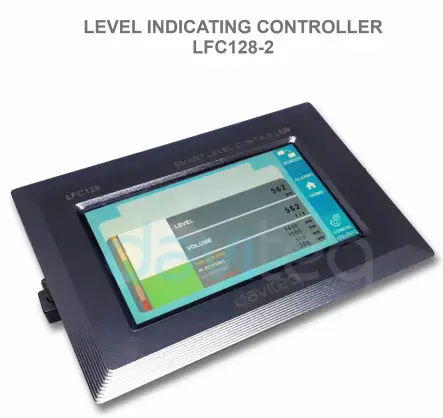
Kontrolluesi i Avancuar i Ekranit të Nivelit LFC128-2
Ky dokument aplikohet për produktet e mëposhtme
| SKU | LFC128-2 | HW Ver. | 1.0 | FW Ver. | 1.1 |
| Kodi i artikullit | LFC128-2 | Kontrollues Tregues i Nivelit, 4AI/DI, 4DI, 4xRele, 1xDalje Impulsi, 2 x Komunikim Skllav RS485/ModbusRTU | |||
Regjistri i Ndryshimeve të Funksioneve
| HW Ver. | FW Ver. | Data e publikimit | Funksionet Ndryshimi |
| 1.0 | 1.1 | QERSHOR-2020 | |
Hyrje
LFC128-2 është një kontrollues i avancuar i ekranit të nivelit. Produkti integron ndërfaqen Modbus RTU për të ndihmuar PLC / SCADA / BMS dhe çdo port IoT mund të lidhet me monitorin. LFC128-2 ka një dizajn të thjeshtë por të fuqishëm me 4 AI / DI, 4 DI, 4 Rele, 1 dalje pulsi pulsi, 2 ModbusRTU Slave RS485 që i lejon ato të lidhen lehtësisht me pajisje të shumta. Me teknologji të përparuar që ofron stabilitet dhe besueshmëri të lartë, shumë funksione, instalim të lehtë me ekran me prekje dhe ndërfaqe miqësore ndihmon në monitorimin vizual të nivelit.
Specifikimi
| Inputet dixhitale | 04 x Ports, opto-coupler, 4.7 kohms input resisrtance, 5000V rms isolation, Logic 0 (0-1VDC), Logic 1 (5-24VDC), Functions: logic status 0/1 or Pulse counting (32 bit counter with max 4kHz pulse) |
| Inputet analoge | 04 x Ports, select between 0-10VDC input or 0-20mA input, 12 bit Resolution, can be configured as Digital input by DIP switch (max 10VDC input) The AI1 port is a 0-10 VDC / 4-20 mA level sensor connection port |
| Rele Output | 04 x Ports, electro-mechanical Relays, SPDT, contact rating 24VDC/2A or 250VAC/5A, LED indicators |
| Dalja e pulsit | 01 x Ports, open-collector, opto-isolation, max 10mA and 80VDC, On/off control, Pulser (max 2.5Khz, max 65535 Pulses) or PWM (max 2.5Khz) |
| Komunikimi | 02 x ModbusRTU-Slave, RS485, shpejtësia 9600 ose 19200, tregues LED |
| Butoni i rivendosjes | For resetting 02 x RS485 Slave port to default setting (9600, None parity, 8 bit) |
| Lloji i ekranit | Ekran me prekje |
| Furnizimi me energji elektrike | 9..36VDC |
| Konsumi | Furnizim 200mA @ 24VDC |
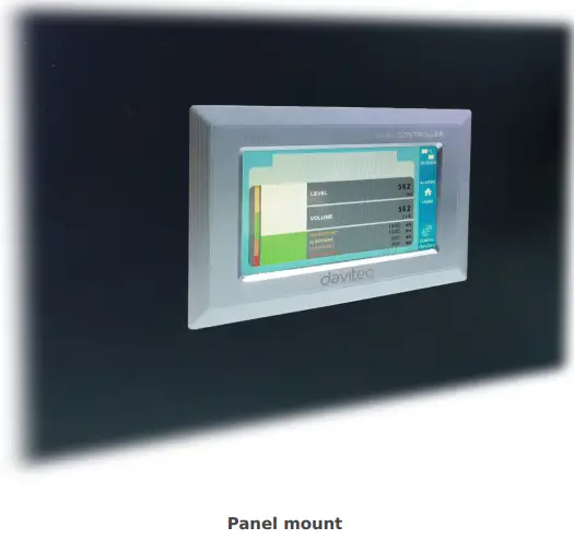
| Lloji i montimit | Montimi i panelit |
| Bllok terminali | hapi 5.0 mm, vlerësimi 300VAC, madhësia e telit 12-24AWG |
| Temperatura / lagështia e punës | 0..60 gradë C / 95%RH pa kondensim |
| Dimensioni | H93xW138xB45 |
| Pesha neto | 390 gram |
Fotot e produktit


Parimi i Operacionit

5.1 Komunikimi Modbus

02 x RS485/ModbusRTU-Slave
Protokolli: Modbus RTU
Adresa: 1 – 247, 0 is the Broadcast address
Norma Baud: 9600, 19200
Pariteti: asnjë, tek, çift
- LED treguesi i statusit:
- Led on: modbus communication OK
- Led blinking: received data but modbus communication incorrect, due to wrong Modbus configuration: address, baudrate
- Led off: LFC128-2 received no data, check the connection
Regjistrues Memmap
READ përdor komandën 03, WRITE përdor komandën 16
Konfigurimi i parazgjedhur:
- Adresa: 1
- Baudrate slave 1: 9600
- Parity slave 1: none
- Baudrate slave 2: 9600
- Parity slave 2: none
| Regjistrohu Modbus | Hex adr | # of registers |
Përshkrimi | Gama | E paracaktuar | Formati | Prona | Koment |
| 0 | 0 | 2 | informacionet e pajisjes | LFC1 | varg | Lexoni | ||
| 8 | 8 | 1 | DI1 DI2: digital status | 0-1 | uint8 | Lexoni | H_bajt: DI1 L_bajt: DI2 | |
| 9 | 9 | 1 | DI3 DI4: digital status | 0-1 | uint8 | Lexoni | H_bajt: DI3 L_bajt: DI4 | |
| 10 | A | 1 | AI1 AI2: digital status | 0-1 | uint8 | Lexoni | H_bajt: AI1 L_bajt: AI2 | |
| 11 | B | 1 | AI3 AI4: digital status | 0-1 | uint8 | Lexoni | H_bajt: AI3 L_bajt: AI4 | |
| 12 | C | 1 | AI1: vlerë analoge | uint16 | Lexoni | |||
| 13 | D | 1 | AI2: vlerë analoge | uint16 | Lexoni | |||
| 14 | E | 1 | AI3: vlerë analoge | uint16 | Lexoni | |||
| 15 | F | 1 | AI4: vlerë analoge | uint16 | Lexoni | |||
| 16 | 10 | 2 | AI1: vlerë e shkallëzuar | noton | Lexoni | |||
| 18 | 12 | 2 | AI2: vlerë e shkallëzuar | noton | Lexoni | |||
| 20 | 14 | 2 | AI3: vlerë e shkallëzuar | noton | Lexoni | |||
| 22 | 16 | 2 | AI4: vlerë e shkallëzuar | noton | Lexoni | |||
| 24 | 18 | 1 | stafetë 1 | 0-1 | uint16 | Lexoni | ||
| 25 | 19 | 1 | stafetë 2 | 0-1 | uint16 | Lexoni | ||
| 26 | 1A | 1 | stafetë 3 | 0-1 | uint16 | Lexoni | ||
| 27 | 1B | 1 | stafetë 4 | 0-1 | uint16 | Lexoni | ||
| 28 | 1C | 1 | kontrollues i kolektorit të hapur | 0-3 | uint16 | Lexo/Shkruaj | 0: fikur 1: ndezur 2: pwm, pulson vazhdimisht 3: pulson, kur ka numër të mjaftueshëm pulsesh, ctrl = 0 | |
| 30 | 1E | 2 | numëruesi DI1 | uint32 | Lexo/Shkruaj | i shkruajtshëm në numërues, i fshishëm | ||
| 32 | 20 | 2 | numëruesi DI2 | uint32 | Lexo/Shkruaj | i shkruajtshëm në numërues, i fshishëm | ||
| 34 | 22 | 2 | numëruesi DI3 | uint32 | Lexo/Shkruaj | i shkruajtshëm në numërues, i fshishëm | ||
| 36 | 24 | 2 | numëruesi DI4 | uint32 | Lexo/Shkruaj | i shkruajtshëm në numërues, i fshishëm | ||
| 38 | 26 | 2 | numëruesi AI1 | uint32 | Lexo/Shkruaj | counter writable, erasable, max frequency 10Hz | ||
| 40 | 28 | 2 | numëruesi AI2 | uint32 | Lexo/Shkruaj | counter writable, erasable, max frequency 10Hz | ||
| 42 | 2A | 2 | numëruesi AI3 | uint32 | Lexo/Shkruaj | counter writable, erasable, max frequency 10Hz | ||
| 44 | 2C | 2 | numëruesi AI4 | uint32 | Lexo/Shkruaj | counter writable, erasable, max frequency 10Hz | ||
| 46 | 2E | 2 | DI1: time on | uint32 | Lexo/Shkruaj | sek | ||
| 48 | 30 | 2 | DI2: time on | uint32 | Lexo/Shkruaj | sek | ||
| 50 | 32 | 2 | DI3: time on | uint32 | Lexo/Shkruaj | sek | ||
| 52 | 34 | 2 | DI4: time on | uint32 | Lexo/Shkruaj | sek | ||
| 54 | 36 | 2 | AI1: time on | uint32 | Lexo/Shkruaj | sek | ||
| 56 | 38 | 2 | AI2: time on | uint32 | Lexo/Shkruaj | sek | ||
| 58 | 3A | 2 | AI3: time on | uint32 | Lexo/Shkruaj | sek | ||
| 60 | 3C | 2 | AI4: time on | uint32 | Lexo/Shkruaj | sek | ||
| 62 | 3E | 2 | DI1: time off | uint32 | Lexo/Shkruaj | sek | ||
| 64 | 40 | 2 | DI2: time off | uint32 | Lexo/Shkruaj | sek | ||
| 66 | 42 | 2 | DI3: time off | uint32 | Lexo/Shkruaj | sek | ||
| 68 | 44 | 2 | DI4: time off | uint32 | Lexo/Shkruaj | sek | ||
| 70 | 46 | 2 | AI1: time off | uint32 | Lexo/Shkruaj | sek | ||
| 72 | 48 | 2 | AI2: time off | uint32 | Lexo/Shkruaj | sek | ||
| 74 | 4A | 2 | AI3: time off | uint32 | Lexo/Shkruaj | sek | ||
| 76 | 4C | 2 | AI4: time off | uint32 | Lexo/Shkruaj | sek | ||
| 128 | 80 | 2 | numëruesi DI1 | uint32 | Lexoni | numëruesi nuk mund të shkruajë, fshijë | ||
| 130 | 82 | 2 | numëruesi DI2 | uint32 | Lexoni | numëruesi nuk mund të shkruajë, fshijë | ||
| 132 | 84 | 2 | numëruesi DI3 | uint32 | Lexoni | numëruesi nuk mund të shkruajë, fshijë | ||
| 134 | 86 | 2 | numëruesi DI4 | uint32 | Lexoni | numëruesi nuk mund të shkruajë, fshijë | ||
| 136 | 88 | 2 | numëruesi AI1 | uint32 | Lexoni | numëruesi nuk mund të shkruajë, fshijë; frekuenca maksimale 10Hz | ||
| 138 | 8A | 2 | numëruesi AI2 | uint32 | Lexoni | numëruesi nuk mund të shkruajë, fshijë; frekuenca maksimale 10Hz | ||
| 140 | 8C | 2 | numëruesi AI3 | uint32 | Lexoni | numëruesi nuk mund të shkruajë, fshijë; frekuenca maksimale 10Hz | ||
| 142 | 8E | 2 | numëruesi AI4 | uint32 | Lexoni | numëruesi nuk mund të shkruajë, fshijë; frekuenca maksimale 10Hz | ||
| 256 | 100 | 1 | adresa skllav i modbusit | 1-247 | 1 | uint16 | Lexo/Shkruaj |
|
| 257 | 101 | 1 | Modbus baudrate skllav 1 | 0-1 | 0 | uint16 | Lexo/Shkruaj |
0: 9600, 1: 19200 |
| 258 | 102 | 1 | skllav pariteti modbus 1 | 0-2 | 0 | uint16 | Lexo/Shkruaj |
0: asnjë, 1: tek, 2: çift |
5.2 Butoni i rivendosjes
When holding the reset button for 4 seconds, LFC 128-2 will reset the default configuration to 02 x RS485 / Modbus
RTU-Slave.
Konfigurimi i parazgjedhur i Modbus RTU:
- Adresa: 1
- Shkalla e Baud: 9600
- Barazi: asnjë
5.3 Hyrja dixhitale

Specifikimi:
- 04 channels DI, isolated
- Input Resistance: 4.7 kΏ
- Izolimi Voltage: 5000 Vrms
- Logic level 0: 0-1V
- Logic level 1: 5-24V
- Funksioni:
- Read logic 0/1
- Njehsuesi i pulseve
5.3.1 Lexoni gjendjen logjike 0/1
Vlera logjike në Hartën e Memories Modbus: 0-1
Regjistrat për të ruajtur vlerat logjike në Hartën e Memories Modbus:
- DI1__DI2: digital status: stores the logical state of channel 1 and channel 2.
H_byte: DI1
L_byte: DI2 - DI3__DI4: digital status: store the logical state of channel 3 and channel 4.
H_byte: DI3
L_byte: DI4
5.3.2 Numëruesi i pulseve
Vlera e numëruesit në Hartën e Memories Modbus, kur shtimi i numrit tejkalon pragun, automatikisht do të kthejë: 0 4294967295 (32 bit)
Regjistri që ruan vlerën e numëruesit në Hartën e Memories Modbus nuk mund të fshihet:
- Numëruesi DI1: ruan gjendjen logjike të kanalit 1
- Numëruesi DI2: ruan gjendjen logjike të kanalit 2
- Counter DI3: store the logic state of channel 3
- Numëruesi DI4: ruan gjendjen logjike të kanalit 4
Regjistri që ruan vlerën e numëruesit në Hartën e Memories Modbus nuk mund të fshihet: - None reset counter DI1: stores the logic state of channel 1
- None reset counter DI2: stores the logic state of channel 2
- None reset counter DI3: stores the logic state of channel 3
- None reset counter DI4: stores the logic state of channel 4
Pulse Counter Mode:
Low-speed pulse count less than 10Hz with filter, anti-jamming:
- Set register “counter DI1: filter time” = 500-2000: Channel 1 counts pulses less than 10Hz
- Set register “counter DI2: filter time” = 500-2000: Channel 2 counts pulses less than 10Hz
- Set register “counter DI3: filter time” = 500-2000: Channel 3 counts pulses less than 10Hz
- Set register “counter DI4: filter time” = 500-2000: Channel 4 counts pulses less than 10Hz
- High-speed pulse count with max 2KHz frequency without filter:
- Set register “counter DI1: filter time” = 1: channel 1 counts pulses with Fmax = 2kHz
- Set register “counter DI2: filter time” = 1: channel 2 counts pulses with Fmax = 2kHz
- Set register “counter DI3: filter time” = 1: channel 3 counts pulses with Fmax = 2kHz
- Set register “counter DI4: filter time” = 1: channel 4 counts pulses with Fmax = 2kHz
5.4 Hyrja analoge
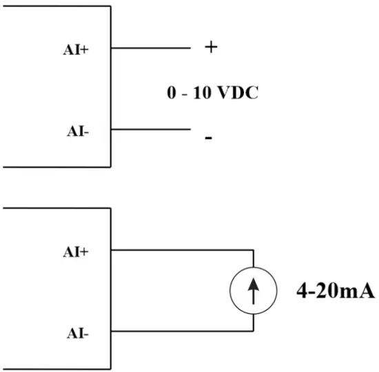
04 kanale AI, pa izolim (AI1 është një hyrje sensori niveli 4-20mA / 0-5 VDC / 0-10 VDC)
Përdorni DIP SW për të konfiguruar hyrjen analoge: 0-10V, 0-20mA
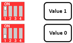
| Vlera | Type of AI |
| 0 | 0-10 V |
| 1 | 0-20 mA |
Lloji i hyrjes:
- Masa vëlltage: 0-10 V
- Measure current: 0-20mA
- The configuration for AI reads the same logical state as DI, but it is not isolated with a pulse range of 0-24V
Impedanca e hyrjes:
- Masa vëlltage: 320 kΏ
- Measure the current: 499 Ώ
5.4.1 Lexoni vlerën analoge
Rezolucioni 12 bit
Jo-Lineariteti: 0.1%
Vlera analoge në Hartën e Memories Modbus: 0-3900
Regjistri i vlerave analoge në Hartën e Memories Modbus:
- AI1 analog value: store the Analog value of channel 1
- AI2 analog value: stores the Analog value of channel 2
- AI3 analog value: store the Analog value of channel 3
- AI4 analog value: store the Analog value of channel 4
5.4.2 Konfigurimi i AI funksionon si DI
Asnjë izolim
AI Konfiguroni AI-në për të lexuar të njëjtën gjendje logjike si DI me puls ampndriçim nga 0-24V
Ekzistojnë 2 pragje të numëruesit AIx: pragu logjik 0 dhe numëruesi AIx: pragu logjik 1 në tabelën modbus: 0-4095
- Analog Analog value of AI <counter AIx: threshold logic 0: is considered Logic 0 status of AI
- Analog Analog value of AI> counter AIx: threshold logic 1: is considered to be Logic 1 state of AI
- Counter AIx: threshold logic 0 = <Analog value of AI <= counter AIx: threshold logic 1: is considered to be the constant logic state
Vlera e statusit logjik të IA-së në tabelën e Hartës së Memories Modbus: 0-1
Regjistri ruan vlerat logjike në Hartën e Memories Modbus:
- AI1___AI2: digital status: stores the logical state of channel 1 and channel 2.
H_byte: AI1
L_byte: AI2 - AI3___AI4: digital status: stores the logical state of channel 1 and channel 2.
H_byte: AI3
L_byte: AI4
5.4.3 Numëruesi i pulseve AI max 10Hz
Vlera e numëruesit në Hartën e Memories Modbus, kur shtohet numri përtej pragut, automatikisht do të kthehet: 0 4294967295 (32 bit)
Regjistri që ruan vlerën e numëruesit në Hartën e Memories Modbus nuk mund të fshihet:
- Counter AI1: stores the logic state of channel 1
- Counter AI2: save logic state of channel 2
- Counter AI3: save logic state of channel 3
- Counter AI4: save logic state of channel 4
Regjistri që ruan vlerën e numëruesit në Hartën e Memories Modbus nuk mund të fshihet: - None reset counter AI1: stores the logic state of channel 1
- None reset counter AI2: stores the logic state of channel 2
- None reset counter AI3: stores the logic state of channel 3
- None reset counter AI4: save logic state of channel 4
5.5 Stafetë
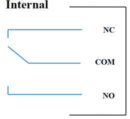
04 channel Relay SPDT NO / NC
Contact rating: 2A / 24VDC, 0.5A / 220VAC
There are status LEDs:
- Led on: Close Contact
- Led off: Open Contact
| Regjistri i parazgjedhur i releve | Status of relays when resetting power supplies |
| 3 | Operate according to the Alarm configuration |
Konfigurimi i alarmit:
- HIHI : Relay 4 On
- HI : Relay 3 On
- LO : Relay 2 On
- LOLO: Relay 1 On
5.6 Dalja e pulsit

01 isolated open-collector channel
Opto-coupler: Source current Imax = 10mA, Vceo = 80V
Funksionet: On / Off, pulse generator, PWM
5.6.1 Funksioni i Ndezjes/Fikjes
Set the Open-collector register in the Modbus Memory Map table:
- Set Open-collector register: 1 => Pulse Output ON
- Set Open-collector register: 0 => Pulse Output OFF
5.6.2 Gjenerator pulsesh
Dalja e pulsit transmeton një maksimum prej 65535 pulsesh, me Fmax 2.5kHz
Konfiguroni regjistrat e mëposhtëm në tabelën e Hartës së Memories Modbus:
- Set register “open collector: pulse number”: 0-65535 => Pulse Number = 65535: broadcast 65535 pulses
- Set register “open collector: time cycle”: (0-65535) x0.1ms => Time Cycle = 4: Fmax 2.5kHz
- Set register “open collector: time on”: (0-65535) x0.1ms => Time On: is the logic time 1 of the pulse
- Set the register “open collector ctrl” = 3 => configure the Pulse Output to generate a pulse and start to pulse, generate a sufficient number of pulses in the “open collector: pulse number” register => stop pulse generator and register ” open collector ctrl ”= 0
5.6.3 PWM
Frekuenca maksimale 2.5kHz
Konfiguroni regjistrat e mëposhtëm në tabelën e Hartës së Memories Modbus:
- Set the register “open collector ctrl” = 2 => configure Pulse Output PWM function
- Set register “open collector: time cycle”: (0-65535) x0.1ms => Time Cycle = 4: Fmax 2.5kHz
- Set register “open collector: time on”: (0-65535) x0.1ms => Time On: is the logic time 1 of the pulse
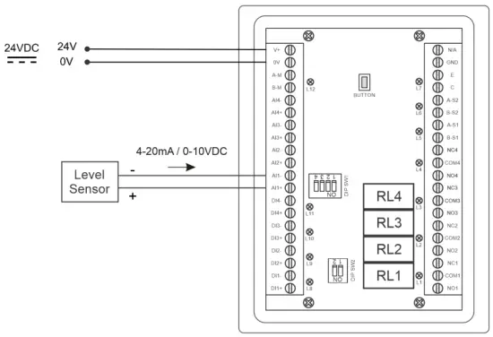
Instalimi
6.1 Mënyra e instalimit
 6.2 Lidhja me Sensorin e Nivelit

Konfigurimi
7.1 Ekrani bazë

EKRANI: Switch to 2nd screen with more detailed information
Alarmet: Show Level Alert
SHTPIA: Kthehu në Ekrani bazë
KONFIGUAR. (Default Password: a): Go to Setting Screen
7.2 Ekrani i konfigurimit (Fjalëkalimi i paracaktuar: a)
7.2.1 Ekrani 1
![daviteq LFC128 2 Advanced Level Display Controller - Home Screen 1] '](https://manuals.plus/wp-content/uploads/2025/08/daviteq-LFC128-2-Advanced-Level-Display-Controller-Home-Screen-1-550x305.png)
ADC-të: Raw signal value of channel AI1
Level (Unit): The level corresponds to the ADC signal after configuration
Decimal Places Level:Decimal number of digits after the dot of Level 0-3 (00000, 1111.1, 222.22, 33.333)
Unit level: level units, 0-3 (0: mm, 1: cm, 2: m, 3: inch)
Në 1: Enter the ADC value after putting 4 mA / 0 VDC into AI1 for calibration at 0 level
Shkalla 1: The level value displayed corresponds to the value entered in In 1 (usually 0)
Në 2: Enter the ADC value after putting 20 mA / 10 VDC into AI1 for calibration at Full level
Shkalla 2: The level value displayed corresponds to the value entered in In 2
Span Level: Maximum value of Level (Span Level ≥ Scale 2)
Decimal Places Volume: Decimal number of digits after the dot of Volume 0-3 (00000, 1111.1, 222.22, 33.333)
Unit Volume: units of volume 0-3 (0: lit, 1: cm, 2: m3, 3:%)
7.2.2 Ekrani 2

Level Hi Hi Set point (Unit): High High level of Alarm Level
Level Hi Hi Hys (Unit): High High level hysteresis of Alarm Level
Level Hi Set point (Unit): High level of Alarm Level
Level Hi Hys (Unit): High level hysteresis of Alarm Level
Level Lo Set point (Unit): Low level of Alarm Level
Level Lo Hys (Unit): Low level hysteresis of Alarm Level
Level Lo Lo Set point (Unit): Low Low level of Alarm Level
Level Lo Lo Hys (Unit): Low Low level hysteresis of Alarm Level
Modaliteti i alarmit: 0: Level, 1: Volume
Span Volume(Unit): Maximum value of the volume
7.2.3 Ekrani 3

Volume Hi Hi Set point (Unit): High High volume of Alarm Volume
Volume Hi Hi Hys (Unit): High High volume hysteresis of Alarm Volume
Volume Hi Set point (Unit): High volume of Alarm Volume
Volume Hi Hys (Unit): High volume hysteresis of Alarm Volume
Volume Lo Set point (Unit): Low volume of Alarm Volume
Volume Lo Hys (Unit): Low volume hysteresis of Alarm Volume
Volume Lo Lo Set point (Unit): Low Low volume of Alarm Volume
Volume Lo Lo Hys (Unit): Low Low volume hysteresis of Alarm Volume
Run Total: Run the total function. 0-1 (0: No 1: Yes)
7.2.4 Ekrani 4

Filling (Unit): Total function: total put into tank
Consumption (Unit): Total function: total consumption of the tank
Decimal Places Total: Decimal number of parameters Filling, Consumption, NRT Filling, NRT Consumption on display page (not the setting page)
Delta Total (Unit): Hysteresis level of the total function
Adresa e Modbus: Modbus address of LFC128-2, 1-247
Modbus Baurate S1: 0-1 (0 : 9600 , 1 : 19200)
Modbus Parity S1: 0-2 (0: none, 1: odd, 2: even)
Modbus Baurate S2: 0-1 (0 : 9600 , 1 : 19200)
Modbus Parity S2: 0-2 (0: none, 1: odd, 2: even)
Num of Points: Number of points in the table to convert from level to volume, 1-166
7.2.5 Ekrani 5

Point 1 Level (Level Unit): Level at Point 1
Point 1 Volume (Volume Unit): The corresponding volume at Point 1
Point 166 Level (Level Unit): Fuel level at Point 166
Point 166 Volume (Volume Unit): The corresponding volume at Point 166
7.2.6 Ekrani 6

Fjalëkalimi: Password to enter the Setting page, 8 ASCII characters
Tank Name: Tank name displayed on the main screen
Zgjidhja e problemeve
| Nr. | Dukuritë | Arsyeja | Zgjidhjet |
| 1 | Modbus dështoi të komunikonte | Modbus LED Status: LED is off: received no data LED is blinking: the Modbus configuration is not the correct | Kontrolloni lidhjen Kontrolloni konfigurimin e Modbus: Adresa, Shpejtësia e Baudit, Pariteti |
| 2 | Kohëzgjatja e Modbus | Zhurma shfaqet në linjë | Konfiguroni Baudrate 9600 dhe përdorni një kabllo të çiftëzuar me mbrojtje kundër bllokimit |
| 3 | Sensori është shkëputur | Sensori dhe LFC128 humbën lidhjen | Checking connection Check sensor type (LFC128-2 only connects to 0-10VDC / 4- 20mA analog sensor type) Check the switch to see if it is turned on correctly Check that the sensor connector is correct AI1 |
| 4 | Gabim në tabelën e linearizimit | Gabim i tabelës së konvertimit nga niveli në vëllim | Kontrolloni konfigurimin e tabelës së konvertimit nga niveli në vëllim |
Kontaktet e mbështetjes
Prodhuesi
Daviteq Technologies Inc
Rruga Nr.11 2G, Nam Hung Vuong Res., An Lac Ward, Binh Tan Dist., Ho Chi Minh City, Vietnam.
Tel: +84-28-6268.2523/4 (ext.122)
Email: info@daviteq.com
www.daviteq.com
Dokumentet / Burimet
 |
Kontrolluesi i Avancuar i Ekranit të Nivelit daviteq LFC128-2 [pdf] Manuali i Udhëzimeve LFC128-2, LFC128-2 Kontrollues i Avancuar i Ekranit të Nivelit, Kontrollues i Avancuar i Ekranit të Nivelit, Kontrollues i Ekranit të Nivelit, Kontrollues i Ekranit |