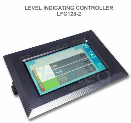
![]() Level Indicating
Level Indicating
Controller LFC128-2
USER GUIDE FOR LEVEL INDICATING CONTROLLER LFC128-2
LFC128-2-MN-EN-01 JUN-2020
LFC128-2 Нарийвчилсан түвшний дэлгэцийн хянагч
Энэхүү баримт бичгийг дараах бүтээгдэхүүнүүдэд хэрэглэнэ
| SKU | LFC128-2 | HW Вер. | 1.0 | FW Вер. | 1.1 |
| Барааны код | LFC128-2 | Level Indicating Controller, 4AI/DI, 4DI, 4xRelay, 1xPulse Output, 2 x RS485/ModbusRTU-Slave Communication | |||
Функц өөрчлөлтийн бүртгэл
| HW Вер. | FW Вер. | Гарсан огноо | Функцүүд Өөрчлөх |
| 1.0 | 1.1 | JUN-2020 | |
Танилцуулга
LFC128-2 is an advanced level display controller. The product integrates Modbus RTU interface to help PLC / SCADA / BMS and any IoT port can connect to monitor. LFC128-2 has a simple yet powerful design with 4 AI / DI, 4 DI, 4 Relays, 1 Pulse pulse output, 2 RS485 Slave ModbusRTU allowing them to connect with multiple devices easily. With advanced technology that provides high stability and reliability, many functions, easy installation with touch screen and friendly interface helps visually monitor level.
Тодорхойлолт
| Дижитал оролтууд | 04 x Ports, opto-coupler, 4.7 kohms input resisrtance, 5000V rms isolation, Logic 0 (0-1VDC), Logic 1 (5-24VDC), Functions: logic status 0/1 or Pulse counting (32 bit counter with max 4kHz pulse) |
| Аналог оролт | 04 x Ports, select between 0-10VDC input or 0-20mA input, 12 bit Resolution, can be configured as Digital input by DIP switch (max 10VDC input) The AI1 port is a 0-10 VDC / 4-20 mA level sensor connection port |
| Реле гаралт | 04 x Ports, electro-mechanical Relays, SPDT, contact rating 24VDC/2A or 250VAC/5A, LED indicators |
| Пульс гаралт | 01 x Ports, open-collector, opto-isolation, max 10mA and 80VDC, On/off control, Pulser (max 2.5Khz, max 65535 Pulses) or PWM (max 2.5Khz) |
| Харилцаа холбоо | 02 x ModbusRTU-Slave, RS485, speed 9600 or 19200, LED indicator |
| Дахин тохируулах товчлуур | For resetting 02 x RS485 Slave port to default setting (9600, None parity, 8 bit) |
| Дэлгэцийн төрөл | Мэдрэгчтэй дэлгэц |
| Цахилгаан хангамж | 9..36VDC |
| Хэрэглээ | 200mA @ 24VDC supply |
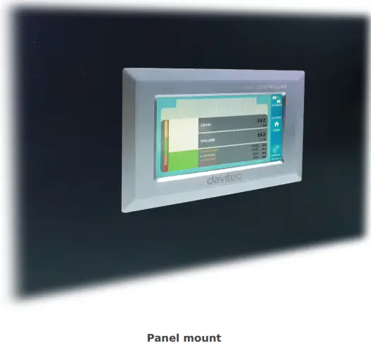
| Суурилуулах төрөл | Самбарын бэхэлгээ |
| Терминал блок | pitch 5.0mm, rating 300VAC, wire size 12-24AWG |
| Ажлын температур / чийгшил | 0..60 degC / 95%RH non-condensing |
| Хэмжээ | H93xW138xD45 |
| Цэвэр жин | 390 грамм |
Бүтээгдэхүүний зураг


Үйл ажиллагааны зарчим

5.1 Modbus холболт

02 x RS485/ModbusRTU-Slave
Протокол: Modbus RTU
Хаяг: 1 – 247, 0 is the Broadcast address
Баудын хурд: 9600, 19200
Паритет: аль нь ч биш, сондгой, тэгш
- Status indicator LED:
- Led on: modbus communication OK
- Led blinking: received data but modbus communication incorrect, due to wrong Modbus configuration: address, baudrate
- Led off: LFC128-2 received no data, check the connection
Memmap бүртгэл
READ uses command 03, WRITE uses command 16
Өгөгдмөл тохиргоо:
- Хаяг: 1
- Baudrate slave 1: 9600
- Parity slave 1: none
- Baudrate slave 2: 9600
- Parity slave 2: none
| Modbus бүртгэл | Hex adr | # of registers |
Тодорхойлолт | Хүрээ | Өгөгдмөл | Формат | Өмч | Сэтгэгдэл |
| 0 | 0 | 2 | төхөөрөмжийн мэдээлэл | LFC1 | мөр | Унших | ||
| 8 | 8 | 1 | DI1 DI2: digital status | 0-1 | uint8 | Унших | H_byte: DI1 L_byte: DI2 | |
| 9 | 9 | 1 | DI3 DI4: digital status | 0-1 | uint8 | Унших | H_byte: DI3 L_byte: DI4 | |
| 10 | A | 1 | AI1 AI2: digital status | 0-1 | uint8 | Унших | H_byte: AI1 L_byte: AI2 | |
| 11 | B | 1 | AI3 AI4: digital status | 0-1 | uint8 | Унших | H_byte: AI3 L_byte: AI4 | |
| 12 | C | 1 | AI1: analog value | uint16 | Унших | |||
| 13 | D | 1 | AI2: analog value | uint16 | Унших | |||
| 14 | E | 1 | AI3: analog value | uint16 | Унших | |||
| 15 | F | 1 | AI4: analog value | uint16 | Унших | |||
| 16 | 10 | 2 | AI1: scaled value | хөвөх | Унших | |||
| 18 | 12 | 2 | AI2: scaled value | хөвөх | Унших | |||
| 20 | 14 | 2 | AI3: scaled value | хөвөх | Унших | |||
| 22 | 16 | 2 | AI4: scaled value | хөвөх | Унших | |||
| 24 | 18 | 1 | реле 1 | 0-1 | uint16 | Унших | ||
| 25 | 19 | 1 | реле 2 | 0-1 | uint16 | Унших | ||
| 26 | 1A | 1 | реле 3 | 0-1 | uint16 | Унших | ||
| 27 | 1B | 1 | реле 4 | 0-1 | uint16 | Унших | ||
| 28 | 1C | 1 | open collector ctrl | 0-3 | uint16 | Унших/бичих | 0: off 1: on 2: pwm, pulse continuously 3: pulse, when enough pulse number, ctrl = 0 | |
| 30 | 1E | 2 | counter DI1 | uint32 | Унших/бичих | counter writable, erasable | ||
| 32 | 20 | 2 | counter DI2 | uint32 | Унших/бичих | counter writable, erasable | ||
| 34 | 22 | 2 | counter DI3 | uint32 | Унших/бичих | counter writable, erasable | ||
| 36 | 24 | 2 | counter DI4 | uint32 | Унших/бичих | counter writable, erasable | ||
| 38 | 26 | 2 | counter AI1 | uint32 | Унших/бичих | counter writable, erasable, max frequency 10Hz | ||
| 40 | 28 | 2 | counter AI2 | uint32 | Унших/бичих | counter writable, erasable, max frequency 10Hz | ||
| 42 | 2A | 2 | counter AI3 | uint32 | Унших/бичих | counter writable, erasable, max frequency 10Hz | ||
| 44 | 2C | 2 | counter AI4 | uint32 | Унших/бичих | counter writable, erasable, max frequency 10Hz | ||
| 46 | 2E | 2 | DI1: time on | uint32 | Унших/бичих | сек | ||
| 48 | 30 | 2 | DI2: time on | uint32 | Унших/бичих | сек | ||
| 50 | 32 | 2 | DI3: time on | uint32 | Унших/бичих | сек | ||
| 52 | 34 | 2 | DI4: time on | uint32 | Унших/бичих | сек | ||
| 54 | 36 | 2 | AI1: time on | uint32 | Унших/бичих | сек | ||
| 56 | 38 | 2 | AI2: time on | uint32 | Унших/бичих | сек | ||
| 58 | 3A | 2 | AI3: time on | uint32 | Унших/бичих | сек | ||
| 60 | 3C | 2 | AI4: time on | uint32 | Унших/бичих | сек | ||
| 62 | 3E | 2 | DI1: time off | uint32 | Унших/бичих | сек | ||
| 64 | 40 | 2 | DI2: time off | uint32 | Унших/бичих | сек | ||
| 66 | 42 | 2 | DI3: time off | uint32 | Унших/бичих | сек | ||
| 68 | 44 | 2 | DI4: time off | uint32 | Унших/бичих | сек | ||
| 70 | 46 | 2 | AI1: time off | uint32 | Унших/бичих | сек | ||
| 72 | 48 | 2 | AI2: time off | uint32 | Унших/бичих | сек | ||
| 74 | 4A | 2 | AI3: time off | uint32 | Унших/бичих | сек | ||
| 76 | 4C | 2 | AI4: time off | uint32 | Унших/бичих | сек | ||
| 128 | 80 | 2 | counter DI1 | uint32 | Унших | counter cannot write, erase | ||
| 130 | 82 | 2 | counter DI2 | uint32 | Унших | counter cannot write, erase | ||
| 132 | 84 | 2 | counter DI3 | uint32 | Унших | counter cannot write, erase | ||
| 134 | 86 | 2 | counter DI4 | uint32 | Унших | counter cannot write, erase | ||
| 136 | 88 | 2 | counter AI1 | uint32 | Унших | counter cannot write, erase; max frequency 10Hz | ||
| 138 | 8A | 2 | counter AI2 | uint32 | Унших | counter cannot write, erase; max frequency 10Hz | ||
| 140 | 8C | 2 | counter AI3 | uint32 | Унших | counter cannot write, erase; max frequency 10Hz | ||
| 142 | 8E | 2 | counter AI4 | uint32 | Унших | counter cannot write, erase; max frequency 10Hz | ||
| 256 | 100 | 1 | modbus address slave | 1-247 | 1 | uint16 | Унших/бичих |
|
| 257 | 101 | 1 | modbus baudrate slave 1 | 0-1 | 0 | uint16 | Унших/бичих |
0: 9600, 1: 19200 |
| 258 | 102 | 1 | modbus parity slave 1 | 0-2 | 0 | uint16 | Унших/бичих |
0: байхгүй, 1: сондгой, 2: тэгш |
5.2 Дахин тохируулах товч
When holding the reset button for 4 seconds, LFC 128-2 will reset the default configuration to 02 x RS485 / Modbus
RTU-Slave.
Default Modbus RTU Configuration:
- Хаяг: 1
- Дамжуулах хурд: 9600
- Паритет: байхгүй
5.3 Дижитал оролт

Үзүүлэлт:
- 04 channels DI, isolated
- Input Resistance: 4.7 kΏ
- Тусгаарлах ботьtage: 5000Vrms
- Logic level 0: 0-1V
- Logic level 1: 5-24V
- Чиг үүрэг:
- Read logic 0/1
- Пульс тоолуур
5.3.1 Read the logical state 0/1
Logic value in Modbus Memory Map: 0-1
Registers to store logic values in the Modbus Memory Map:
- DI1__DI2: digital status: stores the logical state of channel 1 and channel 2.
H_byte: DI1
L_byte: DI2 - DI3__DI4: digital status: store the logical state of channel 3 and channel 4.
H_byte: DI3
L_byte: DI4
5.3.2 Pulse Counter
Counter value in Modbus Memory Map, when adding the number exceeds the threshold, it will automatically return: 0 4294967295 (32bits)
The register that stores Counter value in the Modbus Memory Map cannot be erased:
- Counter DI1: stores the logic state of channel 1
- Counter DI2: stores the logic state of channel 2
- Counter DI3: store the logic state of channel 3
- Counter DI4: stores the logic state of channel 4
The register that stores Counter value in the Modbus Memory Map cannot be erased: - None reset counter DI1: stores the logic state of channel 1
- None reset counter DI2: stores the logic state of channel 2
- None reset counter DI3: stores the logic state of channel 3
- None reset counter DI4: stores the logic state of channel 4
Pulse Counter Mode:
Low-speed pulse count less than 10Hz with filter, anti-jamming:
- Set register “counter DI1: filter time” = 500-2000: Channel 1 counts pulses less than 10Hz
- Set register “counter DI2: filter time” = 500-2000: Channel 2 counts pulses less than 10Hz
- Set register “counter DI3: filter time” = 500-2000: Channel 3 counts pulses less than 10Hz
- Set register “counter DI4: filter time” = 500-2000: Channel 4 counts pulses less than 10Hz
- High-speed pulse count with max 2KHz frequency without filter:
- Set register “counter DI1: filter time” = 1: channel 1 counts pulses with Fmax = 2kHz
- Set register “counter DI2: filter time” = 1: channel 2 counts pulses with Fmax = 2kHz
- Set register “counter DI3: filter time” = 1: channel 3 counts pulses with Fmax = 2kHz
- Set register “counter DI4: filter time” = 1: channel 4 counts pulses with Fmax = 2kHz
5.4 Аналог оролт
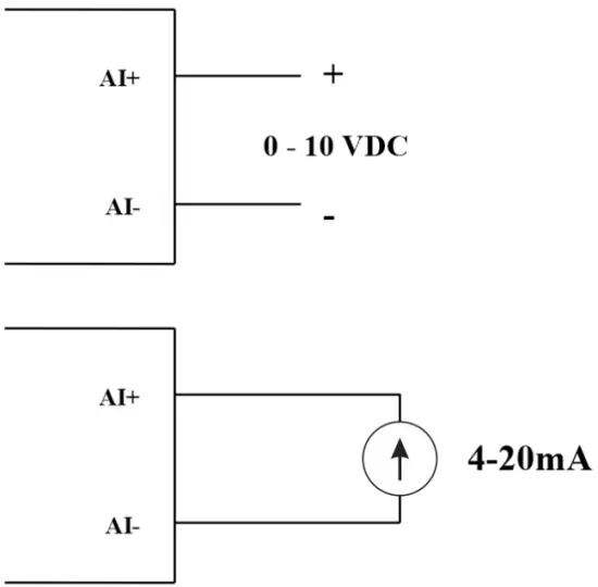
04 AI channels, no isolation (AI1 is a 4-20mA / 0-5 VDC / 0-10 VDC level sensor input )
Use DIP SW to configure Analog input: 0-10V, 0-20mA
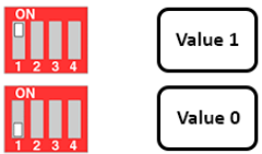
| Үнэ цэнэ | Type of AI |
| 0 | 0-10 В |
| 1 | 0-20 мА |
Оролтын төрөл:
- Эзлэхүүнtagд: 0-10V
- Measure current: 0-20mA
- The configuration for AI reads the same logical state as DI, but it is not isolated with a pulse range of 0-24V
Оролтын эсэргүүцэл:
- Эзлэхүүнtage: 320 kΏ
- Measure the current: 499 Ώ
5.4.1 Read the Analog value
12 битийн нарийвчлал
Non-Linearity: 0.1%
Analog value in Modbus Memory Map: 0-3900
Analog value register in the Modbus Memory Map:
- AI1 analog value: store the Analog value of channel 1
- AI2 analog value: stores the Analog value of channel 2
- AI3 analog value: store the Analog value of channel 3
- AI4 analog value: store the Analog value of channel 4
5.4.2 AI configuration works as DI
Тусгаарлахгүй
AI Configure AI to read the same logic state as DI with pulse amplitude from 0-24V
There are 2 counter threshold AIx: logic threshold 0 and counter AIx: threshold logic 1 in the modbus table: 0-4095
- Analog Analog value of AI <counter AIx: threshold logic 0: is considered Logic 0 status of AI
- Analog Analog value of AI> counter AIx: threshold logic 1: is considered to be Logic 1 state of AI
- Counter AIx: threshold logic 0 = <Analog value of AI <= counter AIx: threshold logic 1: is considered to be the constant logic state
Logic Logical status value of AI in Modbus Memory Map table: 0-1
The register stores logical values in Modbus Memory Map:
- AI1___AI2: digital status: stores the logical state of channel 1 and channel 2.
H_byte: AI1
L_byte: AI2 - AI3___AI4: digital status: stores the logical state of channel 1 and channel 2.
H_byte: AI3
L_byte: AI4
5.4.3 Pulse Counter AI max 10Hz
Counter value in Modbus Memory Map, when adding the number beyond the threshold, it will automatically return: 0 4294967295 (32bits)
The register that stores Counter value in the Modbus Memory Map cannot be erased:
- Counter AI1: stores the logic state of channel 1
- Counter AI2: save logic state of channel 2
- Counter AI3: save logic state of channel 3
- Counter AI4: save logic state of channel 4
The register that stores Counter value in the Modbus Memory Map cannot be erased: - None reset counter AI1: stores the logic state of channel 1
- None reset counter AI2: stores the logic state of channel 2
- None reset counter AI3: stores the logic state of channel 3
- None reset counter AI4: save logic state of channel 4
5.5 Реле
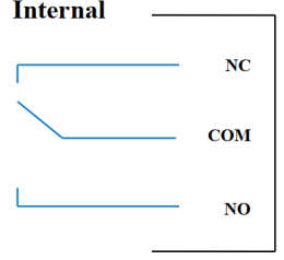
04 channel Relay SPDT NO / NC
Contact rating: 2A / 24VDC, 0.5A / 220VAC
There are status LEDs:
- Led on: Close Contact
- Led off: Open Contact
| Default Relay Register | Status of relays when resetting power supplies |
| 3 | Operate according to the Alarm configuration |
Сэрүүлгийн тохиргоо:
- HIHI : Relay 4 On
- HI : Relay 3 On
- LO : Relay 2 On
- LOLO: Relay 1 On
5.6 Импульсийн гаралт

01 isolated open-collector channel
Opto-coupler: Source current Imax = 10mA, Vceo = 80V
Чиг үүрэг: On / Off, pulse generator, PWM
5.6.1 On/Off Function
Set the Open-collector register in the Modbus Memory Map table:
- Set Open-collector register: 1 => Pulse Output ON
- Set Open-collector register: 0 => Pulse Output OFF
5.6.2 Pulse generator
Pulse output transmits a maximum of 65535 pulses, with Fmax 2.5kHz
Configure the following registers in the Modbus Memory Map table:
- Set register “open collector: pulse number”: 0-65535 => Pulse Number = 65535: broadcast 65535 pulses
- Set register “open collector: time cycle”: (0-65535) x0.1ms => Time Cycle = 4: Fmax 2.5kHz
- Set register “open collector: time on”: (0-65535) x0.1ms => Time On: is the logic time 1 of the pulse
- Set the register “open collector ctrl” = 3 => configure the Pulse Output to generate a pulse and start to pulse, generate a sufficient number of pulses in the “open collector: pulse number” register => stop pulse generator and register ” open collector ctrl ”= 0
5.6.3 ХБХ
Max frequency 2.5kHz
Configure the following registers in the Modbus Memory Map table:
- Set the register “open collector ctrl” = 2 => configure Pulse Output PWM function
- Set register “open collector: time cycle”: (0-65535) x0.1ms => Time Cycle = 4: Fmax 2.5kHz
- Set register “open collector: time on”: (0-65535) x0.1ms => Time On: is the logic time 1 of the pulse
Суурилуулалт
6.1 Суурилуулах арга
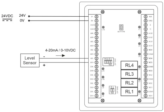
 6.2 Wiring with Level Sensor

Тохиргоо
7.1 Нүүр хуудас

Дэлгэц: Switch to 2nd screen with more detailed information
Сэрүүлэг: Show Level Alert
НҮҮР: Үндсэн дэлгэц рүү буцах
ТОХИРУУЛГА. (Default Password: a): Go to Setting Screen
7.2 Setting screen (Default Password: a)
7.2.1 Дэлгэц 1
![daviteq LFC128 2 Advanced Level Display Controller - Home Screen 1] '](https://manuals.plus/wp-content/uploads/2025/08/daviteq-LFC128-2-Advanced-Level-Display-Controller-Home-Screen-1-550x305.png)
ADC: Raw signal value of channel AI1
Level (Unit): The level corresponds to the ADC signal after configuration
Decimal Places Level:Decimal number of digits after the dot of Level 0-3 (00000, 1111.1, 222.22, 33.333)
Unit level: level units, 0-3 (0: mm, 1: cm, 2: m, 3: inch)
1-д: Enter the ADC value after putting 4 mA / 0 VDC into AI1 for calibration at 0 level
Хэмжээ 1: The level value displayed corresponds to the value entered in In 1 (usually 0)
2-д: Enter the ADC value after putting 20 mA / 10 VDC into AI1 for calibration at Full level
Хэмжээ 2: The level value displayed corresponds to the value entered in In 2
Span Level: Maximum value of Level (Span Level ≥ Scale 2)
Decimal Places Volume: Decimal number of digits after the dot of Volume 0-3 (00000, 1111.1, 222.22, 33.333)
Unit Volume: units of volume 0-3 (0: lit, 1: cm, 2: m3, 3:%)
7.2.2 Дэлгэц 2

Level Hi Hi Set point (Unit): High High level of Alarm Level
Level Hi Hi Hys (Unit): High High level hysteresis of Alarm Level
Level Hi Set point (Unit): High level of Alarm Level
Level Hi Hys (Unit): High level hysteresis of Alarm Level
Level Lo Set point (Unit): Low level of Alarm Level
Level Lo Hys (Unit): Low level hysteresis of Alarm Level
Level Lo Lo Set point (Unit): Low Low level of Alarm Level
Level Lo Lo Hys (Unit): Low Low level hysteresis of Alarm Level
Сэрүүлгийн горим: 0: Level, 1: Volume
Span Volume(Unit): Maximum value of the volume
7.2.3 Дэлгэц 3

Volume Hi Hi Set point (Unit): High High volume of Alarm Volume
Volume Hi Hi Hys (Unit): High High volume hysteresis of Alarm Volume
Volume Hi Set point (Unit): High volume of Alarm Volume
Volume Hi Hys (Unit): High volume hysteresis of Alarm Volume
Volume Lo Set point (Unit): Low volume of Alarm Volume
Volume Lo Hys (Unit): Low volume hysteresis of Alarm Volume
Volume Lo Lo Set point (Unit): Low Low volume of Alarm Volume
Volume Lo Lo Hys (Unit): Low Low volume hysteresis of Alarm Volume
Run Total: Run the total function. 0-1 (0: No 1: Yes)
7.2.4 Дэлгэц 4

Filling (Unit): Total function: total put into tank
Consumption (Unit): Total function: total consumption of the tank
Decimal Places Total: Decimal number of parameters Filling, Consumption, NRT Filling, NRT Consumption on display page (not the setting page)
Delta Total (Unit): Hysteresis level of the total function
Modbus хаяг: Modbus address of LFC128-2, 1-247
Modbus Baurate S1: 0-1 (0 : 9600 , 1 : 19200)
Modbus Parity S1: 0-2 (0: none, 1: odd, 2: even)
Modbus Baurate S2: 0-1 (0 : 9600 , 1 : 19200)
Modbus Parity S2: 0-2 (0: none, 1: odd, 2: even)
Num of Points: Number of points in the table to convert from level to volume, 1-166
7.2.5 Дэлгэц 5

Point 1 Level (Level Unit): Level at Point 1
Point 1 Volume (Volume Unit): The corresponding volume at Point 1
Point 166 Level (Level Unit): Fuel level at Point 166
Point 166 Volume (Volume Unit): The corresponding volume at Point 166
7.2.6 Дэлгэц 6

Нууц үг: Password to enter the Setting page, 8 ASCII characters
Tank Name: Tank name displayed on the main screen
Алдааг олж засварлах
| Үгүй | Үзэгдэл | Шалтгаан | Шийдэл |
| 1 | Modbus failed to communicate | Modbus LED Status: LED is off: received no data LED is blinking: the Modbus configuration is not the correct | Check the connection Check the Modbus configuration: Address, Baud Rate, Parity |
| 2 | Timeout Modbus | Noise appears on the line | Configure Baudrate 9600 and use a twisted pair cable with anti-jamming protection |
| 3 | Мэдрэгч салгагдсан | Sensor and LFC128 lost connection | Checking connection Check sensor type (LFC128-2 only connects to 0-10VDC / 4- 20mA analog sensor type) Check the switch to see if it is turned on correctly Check that the sensor connector is correct AI1 |
| 4 | Linearization table error | Error of conversion table from level to volume | Check the configuration of the conversion table from level to volume |
Харилцагчдыг дэмжих
Үйлдвэрлэгч
Daviteq Technologies Inc
№11 гудамж 2G, Нам Хунг Вуонг рес., Ан Лак тойрог, Бин Тан дүүрэг, Хо Ши Мин хот, Вьетнам.
Tel: +84-28-6268.2523/4 (ext.122)
Имэйл: info@daviteq.com
www.daviteq.com
Баримт бичиг / нөөц
 |
daviteq LFC128-2 Advanced Level Display Controller [pdf] Зааварчилгааны гарын авлага LFC128-2, LFC128-2 Advanced Level Display Controller, Advanced Level Display Controller, Level Display Controller, Display Controller |