![]() Level Indicating
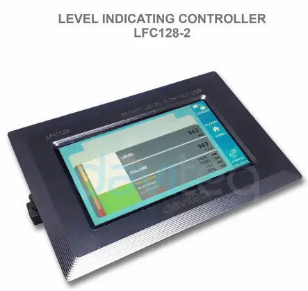
Level Indicating
Controller LFC128-2
લેવલ સૂચક નિયંત્રક LFC128-2 માટે વપરાશકર્તા માર્ગદર્શિકા
LFC128-2-MN-EN-01 JUN-2020
LFC128-2 એડવાન્સ્ડ લેવલ ડિસ્પ્લે કંટ્રોલર
આ દસ્તાવેજ નીચેના ઉત્પાદનો માટે લાગુ કરવામાં આવે છે
| SKU | LFC128-2 | HW Ver. | 1.0 | FW Ver. | 1.1 |
| આઇટમ કોડ | LFC128-2 | લેવલ ઈન્ડિકેટિંગ કંટ્રોલર, 4AI/DI, 4DI, 4xRelay, 1xPulse આઉટપુટ, 2 x RS485/ModbusRTU-સ્લેવ કોમ્યુનિકેશન | |||
કાર્યો બદલો લોગ
| HW Ver. | FW Ver. | પ્રકાશન તારીખ | કાર્યો બદલો |
| 1.0 | 1.1 | જૂન-૨૦૨૦ | |
પરિચય
LFC128-2 એ એક એડવાન્સ્ડ લેવલ ડિસ્પ્લે કંટ્રોલર છે. આ પ્રોડક્ટ PLC / SCADA / BMS ને મદદ કરવા માટે Modbus RTU ઇન્ટરફેસને એકીકૃત કરે છે અને કોઈપણ IoT પોર્ટ મોનિટર સાથે કનેક્ટ થઈ શકે છે. LFC128-2 માં 4 AI / DI, 4 DI, 4 રિલે, 1 પલ્સ પલ્સ આઉટપુટ, 2 RS485 સ્લેવ ModbusRTU સાથે એક સરળ છતાં શક્તિશાળી ડિઝાઇન છે જે તેમને બહુવિધ ઉપકરણો સાથે સરળતાથી કનેક્ટ થવા દે છે. ઉચ્ચ સ્થિરતા અને વિશ્વસનીયતા, ઘણા કાર્યો, ટચ સ્ક્રીન સાથે સરળ ઇન્સ્ટોલેશન અને મૈત્રીપૂર્ણ ઇન્ટરફેસ પ્રદાન કરતી અદ્યતન ટેકનોલોજી સાથે, સ્તરને દૃષ્ટિની રીતે મોનિટર કરવામાં મદદ કરે છે.
સ્પષ્ટીકરણ
| ડિજિટલ ઇનપુટ્સ | 04 x Ports, opto-coupler, 4.7 kohms input resisrtance, 5000V rms isolation, Logic 0 (0-1VDC), Logic 1 (5-24VDC), Functions: logic status 0/1 or Pulse counting (32 bit counter with max 4kHz pulse) |
| એનાલોગ ઇનપુટ્સ | 04 x Ports, select between 0-10VDC input or 0-20mA input, 12 bit Resolution, can be configured as Digital input by DIP switch (max 10VDC input) The AI1 port is a 0-10 VDC / 4-20 mA level sensor connection port |
| રિલે આઉટપુટ | 04 x Ports, electro-mechanical Relays, SPDT, contact rating 24VDC/2A or 250VAC/5A, LED indicators |
| પલ્સ આઉટપુટ | 01 x Ports, open-collector, opto-isolation, max 10mA and 80VDC, On/off control, Pulser (max 2.5Khz, max 65535 Pulses) or PWM (max 2.5Khz) |
| કોમ્યુનિકેશન | 02 x મોડબસઆરટીયુ-સ્લેવ, RS485, સ્પીડ 9600 અથવા 19200, એલઇડી સૂચક |
| રીસેટ બટન | For resetting 02 x RS485 Slave port to default setting (9600, None parity, 8 bit) |
| સ્ક્રીન પ્રકાર | ટચ સ્ક્રીન |
| વીજ પુરવઠો | 9..36VDC |
| વપરાશ | 200VDC પર 24mA સપ્લાય |
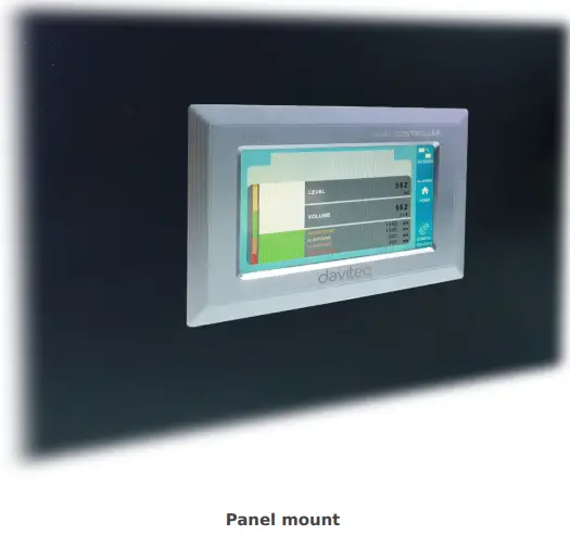
| માઉન્ટિંગ પ્રકાર | પેનલ માઉન્ટ |
| ટર્મિનલ બ્લોક | પિચ 5.0mm, રેટિંગ 300VAC, વાયરનું કદ 12-24AWG |
| કાર્યકારી તાપમાન / ભેજ | 0..60 ડિગ્રી સેલ્સિયસ / 95% આરએચ નોન-કન્ડેન્સિંગ |
| પરિમાણ | H93xW138xD45 |
| ચોખ્ખું વજન | 390 ગ્રામ |
ઉત્પાદન ચિત્રો


ઓપરેશન સિદ્ધાંત

5.1 મોડબસ સંચાર

02 x RS485/ModbusRTU-Slave
પ્રોટોકોલ: મોડબસ આરટીયુ
સરનામું: 1 – 247, 0 is the Broadcast address
બૌડ દર: ૧૫, ૨૧
સમાનતા: કોઈ નહીં, વિચિત્ર, સમ
- સ્થિતિ સૂચક LED:
- Led on: modbus communication OK
- Led blinking: received data but modbus communication incorrect, due to wrong Modbus configuration: address, baudrate
- Led off: LFC128-2 received no data, check the connection
મેમમેપ રજીસ્ટર
READ આદેશ 03 નો ઉપયોગ કરે છે, WRITE આદેશ 16 નો ઉપયોગ કરે છે
ડિફૉલ્ટ રૂપરેખાંકન:
- સરનામું: 1
- Baudrate slave 1: 9600
- Parity slave 1: none
- Baudrate slave 2: 9600
- Parity slave 2: none
| મોડબસ રજીસ્ટર | Hex adr | # of registers |
વર્ણન | શ્રેણી | ડિફૉલ્ટ | ફોર્મેટ | મિલકત | ટિપ્પણી |
| 0 | 0 | 2 | ઉપકરણ માહિતી | LFC1 | શબ્દમાળા | વાંચો | ||
| 8 | 8 | 1 | DI1 DI2: digital status | 0-1 | uint8 | વાંચો | H_બાઇટ: DI1 L_બાઇટ: DI2 | |
| 9 | 9 | 1 | DI3 DI4: digital status | 0-1 | uint8 | વાંચો | H_બાઇટ: DI3 L_બાઇટ: DI4 | |
| 10 | A | 1 | એઆઈ 1 AI2: digital status | 0-1 | uint8 | વાંચો | H_બાઇટ: AI1 L_બાઇટ: AI2 | |
| 11 | B | 1 | એઆઈ 3 AI4: digital status | 0-1 | uint8 | વાંચો | H_બાઇટ: AI3 L_બાઇટ: AI4 | |
| 12 | C | 1 | AI1: એનાલોગ મૂલ્ય | uint16 | વાંચો | |||
| 13 | D | 1 | AI2: એનાલોગ મૂલ્ય | uint16 | વાંચો | |||
| 14 | E | 1 | AI3: એનાલોગ મૂલ્ય | uint16 | વાંચો | |||
| 15 | F | 1 | AI4: એનાલોગ મૂલ્ય | uint16 | વાંચો | |||
| 16 | 10 | 2 | AI1: સ્કેલ કરેલ મૂલ્ય | ફ્લોટ | વાંચો | |||
| 18 | 12 | 2 | AI2: સ્કેલ કરેલ મૂલ્ય | ફ્લોટ | વાંચો | |||
| 20 | 14 | 2 | AI3: સ્કેલ કરેલ મૂલ્ય | ફ્લોટ | વાંચો | |||
| 22 | 16 | 2 | AI4: સ્કેલ કરેલ મૂલ્ય | ફ્લોટ | વાંચો | |||
| 24 | 18 | 1 | રિલે 1 | 0-1 | uint16 | વાંચો | ||
| 25 | 19 | 1 | રિલે 2 | 0-1 | uint16 | વાંચો | ||
| 26 | 1A | 1 | રિલે 3 | 0-1 | uint16 | વાંચો | ||
| 27 | 1B | 1 | રિલે 4 | 0-1 | uint16 | વાંચો | ||
| 28 | 1C | 1 | ઓપન કલેક્ટર Ctrl | 0-3 | uint16 | વાંચો/લખો | ૦: બંધ ૧: ૨ પર: pwm, સતત પલ્સ ૩: પલ્સ, જ્યારે પૂરતો પલ્સ નંબર હોય, ctrl = ૦ | |
| 30 | 1E | 2 | કાઉન્ટર DI1 | uint32 | વાંચો/લખો | પ્રતિ-લખી શકાય તેવું, ભૂંસી શકાય તેવું | ||
| 32 | 20 | 2 | કાઉન્ટર DI2 | uint32 | વાંચો/લખો | પ્રતિ-લખી શકાય તેવું, ભૂંસી શકાય તેવું | ||
| 34 | 22 | 2 | કાઉન્ટર DI3 | uint32 | વાંચો/લખો | પ્રતિ-લખી શકાય તેવું, ભૂંસી શકાય તેવું | ||
| 36 | 24 | 2 | કાઉન્ટર DI4 | uint32 | વાંચો/લખો | પ્રતિ-લખી શકાય તેવું, ભૂંસી શકાય તેવું | ||
| 38 | 26 | 2 | કાઉન્ટર AI1 | uint32 | વાંચો/લખો | counter writable, erasable, max frequency 10Hz | ||
| 40 | 28 | 2 | કાઉન્ટર AI2 | uint32 | વાંચો/લખો | counter writable, erasable, max frequency 10Hz | ||
| 42 | 2A | 2 | કાઉન્ટર AI3 | uint32 | વાંચો/લખો | counter writable, erasable, max frequency 10Hz | ||
| 44 | 2C | 2 | કાઉન્ટર AI4 | uint32 | વાંચો/લખો | counter writable, erasable, max frequency 10Hz | ||
| 46 | 2E | 2 | DI1: time on | uint32 | વાંચો/લખો | સેકન્ડ | ||
| 48 | 30 | 2 | DI2: time on | uint32 | વાંચો/લખો | સેકન્ડ | ||
| 50 | 32 | 2 | DI3: time on | uint32 | વાંચો/લખો | સેકન્ડ | ||
| 52 | 34 | 2 | DI4: time on | uint32 | વાંચો/લખો | સેકન્ડ | ||
| 54 | 36 | 2 | AI1: time on | uint32 | વાંચો/લખો | સેકન્ડ | ||
| 56 | 38 | 2 | AI2: time on | uint32 | વાંચો/લખો | સેકન્ડ | ||
| 58 | 3A | 2 | AI3: time on | uint32 | વાંચો/લખો | સેકન્ડ | ||
| 60 | 3C | 2 | AI4: time on | uint32 | વાંચો/લખો | સેકન્ડ | ||
| 62 | 3E | 2 | DI1: time off | uint32 | વાંચો/લખો | સેકન્ડ | ||
| 64 | 40 | 2 | DI2: time off | uint32 | વાંચો/લખો | સેકન્ડ | ||
| 66 | 42 | 2 | DI3: time off | uint32 | વાંચો/લખો | સેકન્ડ | ||
| 68 | 44 | 2 | DI4: time off | uint32 | વાંચો/લખો | સેકન્ડ | ||
| 70 | 46 | 2 | AI1: time off | uint32 | વાંચો/લખો | સેકન્ડ | ||
| 72 | 48 | 2 | AI2: time off | uint32 | વાંચો/લખો | સેકન્ડ | ||
| 74 | 4A | 2 | AI3: time off | uint32 | વાંચો/લખો | સેકન્ડ | ||
| 76 | 4C | 2 | AI4: time off | uint32 | વાંચો/લખો | સેકન્ડ | ||
| 128 | 80 | 2 | કાઉન્ટર DI1 | uint32 | વાંચો | કાઉન્ટર લખી, ભૂંસી શકતો નથી | ||
| 130 | 82 | 2 | કાઉન્ટર DI2 | uint32 | વાંચો | કાઉન્ટર લખી, ભૂંસી શકતો નથી | ||
| 132 | 84 | 2 | કાઉન્ટર DI3 | uint32 | વાંચો | કાઉન્ટર લખી, ભૂંસી શકતો નથી | ||
| 134 | 86 | 2 | કાઉન્ટર DI4 | uint32 | વાંચો | કાઉન્ટર લખી, ભૂંસી શકતો નથી | ||
| 136 | 88 | 2 | કાઉન્ટર AI1 | uint32 | વાંચો | કાઉન્ટર લખી, ભૂંસી શકતો નથી; મહત્તમ આવર્તન 10Hz | ||
| 138 | 8A | 2 | કાઉન્ટર AI2 | uint32 | વાંચો | કાઉન્ટર લખી, ભૂંસી શકતો નથી; મહત્તમ આવર્તન 10Hz | ||
| 140 | 8C | 2 | કાઉન્ટર AI3 | uint32 | વાંચો | કાઉન્ટર લખી, ભૂંસી શકતો નથી; મહત્તમ આવર્તન 10Hz | ||
| 142 | 8E | 2 | કાઉન્ટર AI4 | uint32 | વાંચો | કાઉન્ટર લખી, ભૂંસી શકતો નથી; મહત્તમ આવર્તન 10Hz | ||
| 256 | 100 | 1 | મોડબસ સરનામું સ્લેવ | 1-247 | 1 | uint16 | વાંચો/લખો |
|
| 257 | 101 | 1 | મોડબસ બોડ્રેટ સ્લેવ 1 | 0-1 | 0 | uint16 | વાંચો/લખો |
0: 9600, 1: 19200 |
| 258 | 102 | 1 | મોડબસ પેરિટી સ્લેવ 1 | 0-2 | 0 | uint16 | વાંચો/લખો |
0: કોઈ નહીં, 1: વિષમ, 2: સમાન |
5.2 રીસેટ બટન
When holding the reset button for 4 seconds, LFC 128-2 will reset the default configuration to 02 x RS485 / Modbus
RTU-Slave.
ડિફોલ્ટ મોડબસ RTU રૂપરેખાંકન:
- સરનામું: 1
- બૉડ રેટ: 9600
- સમાનતા: કોઈ નહીં
5.3 ડિજિટલ ઇનપુટ

સ્પષ્ટીકરણ:
- 04 channels DI, isolated
- Input Resistance: 4.7 kΏ
- અલગતા ભાગtage: 5000Vrms
- Logic level 0: 0-1V
- Logic level 1: 5-24V
- કાર્ય:
- Read logic 0/1
- પલ્સ કાઉન્ટર
૫.૩.૧ લોજિકલ સ્થિતિ ૦/૧ વાંચો
મોડબસ મેમરી મેપમાં લોજિક મૂલ્ય: 0-1
મોડબસ મેમરી મેપમાં લોજિક મૂલ્યો સંગ્રહિત કરવા માટે રજીસ્ટર:
- DI1__DI2: digital status: stores the logical state of channel 1 and channel 2.
H_byte: DI1
L_byte: DI2 - DI3__DI4: digital status: store the logical state of channel 3 and channel 4.
H_byte: DI3
L_byte: DI4
૫.૩.૨ પલ્સ કાઉન્ટર
મોડબસ મેમરી મેપમાં કાઉન્ટર વેલ્યુ, જ્યારે સંખ્યા થ્રેશોલ્ડ કરતાં વધી જાય છે, ત્યારે તે આપમેળે પરત આવશે: 0 4294967295 (32bits)
મોડબસ મેમરી મેપમાં કાઉન્ટર વેલ્યુ સ્ટોર કરતું રજિસ્ટર ભૂંસી શકાતું નથી:
- કાઉન્ટર DI1: ચેનલ 1 ની લોજિક સ્થિતિ સંગ્રહિત કરે છે.
- કાઉન્ટર DI2: ચેનલ 2 ની લોજિક સ્થિતિ સંગ્રહિત કરે છે.
- Counter DI3: store the logic state of channel 3
- કાઉન્ટર DI4: ચેનલ 4 ની લોજિક સ્થિતિ સંગ્રહિત કરે છે.
મોડબસ મેમરી મેપમાં કાઉન્ટર વેલ્યુ સ્ટોર કરતું રજિસ્ટર ભૂંસી શકાતું નથી: - None reset counter DI1: stores the logic state of channel 1
- None reset counter DI2: stores the logic state of channel 2
- None reset counter DI3: stores the logic state of channel 3
- None reset counter DI4: stores the logic state of channel 4
Pulse Counter Mode:
Low-speed pulse count less than 10Hz with filter, anti-jamming:
- Set register “counter DI1: filter time” = 500-2000: Channel 1 counts pulses less than 10Hz
- Set register “counter DI2: filter time” = 500-2000: Channel 2 counts pulses less than 10Hz
- Set register “counter DI3: filter time” = 500-2000: Channel 3 counts pulses less than 10Hz
- Set register “counter DI4: filter time” = 500-2000: Channel 4 counts pulses less than 10Hz
- High-speed pulse count with max 2KHz frequency without filter:
- Set register “counter DI1: filter time” = 1: channel 1 counts pulses with Fmax = 2kHz
- Set register “counter DI2: filter time” = 1: channel 2 counts pulses with Fmax = 2kHz
- Set register “counter DI3: filter time” = 1: channel 3 counts pulses with Fmax = 2kHz
- Set register “counter DI4: filter time” = 1: channel 4 counts pulses with Fmax = 2kHz
5.4 એનાલોગ ઇનપુટ
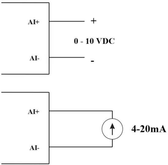
04 AI ચેનલો, કોઈ આઇસોલેશન નથી (AI1 એ 4-20mA / 0-5 VDC / 0-10 VDC લેવલ સેન્સર ઇનપુટ છે)
એનાલોગ ઇનપુટ ગોઠવવા માટે DIP SW નો ઉપયોગ કરો: 0-10V, 0-20mA
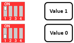
| મૂલ્ય | Type of AI |
| 0 | 0-10 વી |
| 1 | 0-20 એમએ |
ઇનપુટ પ્રકાર:
- વોલ્યુમ માપtage: 0-10V
- Measure current: 0-20mA
- The configuration for AI reads the same logical state as DI, but it is not isolated with a pulse range of 0-24V
ઇનપુટ અવબાધ:
- વોલ્યુમ માપtage: 320 kΏ
- Measure the current: 499 Ώ
૫.૪.૧ એનાલોગ મૂલ્ય વાંચો
ઠરાવ 12 બિટ્સ
બિન-રેખીયતા: 0.1%
મોડબસ મેમરી મેપમાં એનાલોગ મૂલ્ય: 0-3900
મોડબસ મેમરી મેપમાં એનાલોગ વેલ્યુ રજિસ્ટર:
- AI1 analog value: store the Analog value of channel 1
- AI2 analog value: stores the Analog value of channel 2
- AI3 analog value: store the Analog value of channel 3
- AI4 analog value: store the Analog value of channel 4
૫.૪.૨ AI રૂપરેખાંકન DI તરીકે કામ કરે છે
કોઈ અલગતા નથી
AI પલ્સ સાથે DI જેવી જ લોજિક સ્થિતિ વાંચવા માટે AI ને ગોઠવો. amp0-24V થી ઊંચું
મોડબસ ટેબલમાં 2 કાઉન્ટર થ્રેશોલ્ડ AIx: લોજિક થ્રેશોલ્ડ 0 અને કાઉન્ટર AIx: થ્રેશોલ્ડ લોજિક 1 છે: 0-4095
- Analog Analog value of AI <counter AIx: threshold logic 0: is considered Logic 0 status of AI
- Analog Analog value of AI> counter AIx: threshold logic 1: is considered to be Logic 1 state of AI
- Counter AIx: threshold logic 0 = <Analog value of AI <= counter AIx: threshold logic 1: is considered to be the constant logic state
મોડબસ મેમરી મેપ ટેબલમાં AI નું લોજિક લોજિકલ સ્ટેટસ મૂલ્ય: 0-1
રજિસ્ટર મોડબસ મેમરી મેપમાં લોજિકલ મૂલ્યો સંગ્રહિત કરે છે:
- AI1___AI2: digital status: stores the logical state of channel 1 and channel 2.
H_byte: AI1
L_byte: AI2 - AI3___AI4: digital status: stores the logical state of channel 1 and channel 2.
H_byte: AI3
L_byte: AI4
૫.૪.૩ પલ્સ કાઉન્ટર AI મહત્તમ ૧૦Hz
મોડબસ મેમરી મેપમાં કાઉન્ટર વેલ્યુ, થ્રેશોલ્ડની બહાર નંબર ઉમેરતી વખતે, તે આપમેળે પરત આવશે: 0 4294967295 (32bits)
મોડબસ મેમરી મેપમાં કાઉન્ટર વેલ્યુ સ્ટોર કરતું રજિસ્ટર ભૂંસી શકાતું નથી:
- Counter AI1: stores the logic state of channel 1
- Counter AI2: save logic state of channel 2
- Counter AI3: save logic state of channel 3
- Counter AI4: save logic state of channel 4
મોડબસ મેમરી મેપમાં કાઉન્ટર વેલ્યુ સ્ટોર કરતું રજિસ્ટર ભૂંસી શકાતું નથી: - None reset counter AI1: stores the logic state of channel 1
- None reset counter AI2: stores the logic state of channel 2
- None reset counter AI3: stores the logic state of channel 3
- None reset counter AI4: save logic state of channel 4
5.5 રિલે
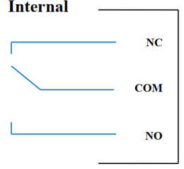
04 channel Relay SPDT NO / NC
Contact rating: 2A / 24VDC, 0.5A / 220VAC
There are status LEDs:
- Led on: Close Contact
- Led off: Open Contact
| ડિફોલ્ટ રિલે રજિસ્ટર | Status of relays when resetting power supplies |
| 3 | Operate according to the Alarm configuration |
એલાર્મ રૂપરેખાંકન:
- HIHI : Relay 4 On
- HI : Relay 3 On
- LO : Relay 2 On
- LOLO: Relay 1 On
5.6 પલ્સ આઉટપુટ

01 isolated open-collector channel
Opto-coupler: Source current Imax = 10mA, Vceo = 80V
કાર્યો: On / Off, pulse generator, PWM
૫.૬.૧ ચાલુ/બંધ કાર્ય
Set the Open-collector register in the Modbus Memory Map table:
- Set Open-collector register: 1 => Pulse Output ON
- Set Open-collector register: 0 => Pulse Output OFF
૫.૬.૨ પલ્સ જનરેટર
પલ્સ આઉટપુટ મહત્તમ 65535 પલ્સ ટ્રાન્સમિટ કરે છે, Fmax 2.5kHz સાથે
મોડબસ મેમરી મેપ ટેબલમાં નીચેના રજિસ્ટર ગોઠવો:
- Set register “open collector: pulse number”: 0-65535 => Pulse Number = 65535: broadcast 65535 pulses
- Set register “open collector: time cycle”: (0-65535) x0.1ms => Time Cycle = 4: Fmax 2.5kHz
- Set register “open collector: time on”: (0-65535) x0.1ms => Time On: is the logic time 1 of the pulse
- Set the register “open collector ctrl” = 3 => configure the Pulse Output to generate a pulse and start to pulse, generate a sufficient number of pulses in the “open collector: pulse number” register => stop pulse generator and register ” open collector ctrl ”= 0
5.6.3 PWM
મહત્તમ આવર્તન 2.5kHz
મોડબસ મેમરી મેપ ટેબલમાં નીચેના રજિસ્ટર ગોઠવો:
- Set the register “open collector ctrl” = 2 => configure Pulse Output PWM function
- Set register “open collector: time cycle”: (0-65535) x0.1ms => Time Cycle = 4: Fmax 2.5kHz
- Set register “open collector: time on”: (0-65535) x0.1ms => Time On: is the logic time 1 of the pulse
સ્થાપન
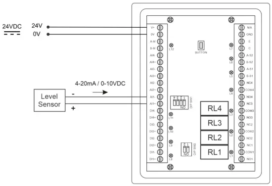
6.1 સ્થાપન પદ્ધતિ
 ૬.૨ લેવલ સેન્સર સાથે વાયરિંગ

રૂપરેખાંકન
7.1 હોમ સ્ક્રીન

સ્ક્રીન: Switch to 2nd screen with more detailed information
એલાર્મ્સ: Show Level Alert
ઘર: હોમ સ્ક્રીન પર પાછા ફરો
CONFIG. (Default Password: a): Go to Setting Screen
૭.૨ સેટિંગ સ્ક્રીન (ડિફોલ્ટ પાસવર્ડ: a)
7.2.1 સ્ક્રીન 1
![daviteq LFC128 2 Advanced Level Display Controller - Home Screen 1] '](https://manuals.plus/wp-content/uploads/2025/08/daviteq-LFC128-2-Advanced-Level-Display-Controller-Home-Screen-1-550x305.png)
ADCs: Raw signal value of channel AI1
Level (Unit): The level corresponds to the ADC signal after configuration
Decimal Places Level:Decimal number of digits after the dot of Level 0-3 (00000, 1111.1, 222.22, 33.333)
Unit level: level units, 0-3 (0: mm, 1: cm, 2: m, 3: inch)
1 માં: Enter the ADC value after putting 4 mA / 0 VDC into AI1 for calibration at 0 level
સ્કેલ 1: The level value displayed corresponds to the value entered in In 1 (usually 0)
2 માં: Enter the ADC value after putting 20 mA / 10 VDC into AI1 for calibration at Full level
સ્કેલ 2: The level value displayed corresponds to the value entered in In 2
Span Level: Maximum value of Level (Span Level ≥ Scale 2)
Decimal Places Volume: Decimal number of digits after the dot of Volume 0-3 (00000, 1111.1, 222.22, 33.333)
Unit Volume: units of volume 0-3 (0: lit, 1: cm, 2: m3, 3:%)
7.2.2 સ્ક્રીન 2

Level Hi Hi Set point (Unit): High High level of Alarm Level
Level Hi Hi Hys (Unit): High High level hysteresis of Alarm Level
Level Hi Set point (Unit): High level of Alarm Level
Level Hi Hys (Unit): High level hysteresis of Alarm Level
Level Lo Set point (Unit): Low level of Alarm Level
Level Lo Hys (Unit): Low level hysteresis of Alarm Level
Level Lo Lo Set point (Unit): Low Low level of Alarm Level
Level Lo Lo Hys (Unit): Low Low level hysteresis of Alarm Level
એલાર્મ મોડ: 0: Level, 1: Volume
Span Volume(Unit): Maximum value of the volume
7.2.3 સ્ક્રીન 3

Volume Hi Hi Set point (Unit): High High volume of Alarm Volume
Volume Hi Hi Hys (Unit): High High volume hysteresis of Alarm Volume
Volume Hi Set point (Unit): High volume of Alarm Volume
Volume Hi Hys (Unit): High volume hysteresis of Alarm Volume
Volume Lo Set point (Unit): Low volume of Alarm Volume
Volume Lo Hys (Unit): Low volume hysteresis of Alarm Volume
Volume Lo Lo Set point (Unit): Low Low volume of Alarm Volume
Volume Lo Lo Hys (Unit): Low Low volume hysteresis of Alarm Volume
Run Total: Run the total function. 0-1 (0: No 1: Yes)
7.2.4 સ્ક્રીન 4

Filling (Unit): Total function: total put into tank
Consumption (Unit): Total function: total consumption of the tank
Decimal Places Total: Decimal number of parameters Filling, Consumption, NRT Filling, NRT Consumption on display page (not the setting page)
Delta Total (Unit): Hysteresis level of the total function
મોડબસ સરનામું: Modbus address of LFC128-2, 1-247
Modbus Baurate S1: 0-1 (0 : 9600 , 1 : 19200)
Modbus Parity S1: 0-2 (0: none, 1: odd, 2: even)
Modbus Baurate S2: 0-1 (0 : 9600 , 1 : 19200)
Modbus Parity S2: 0-2 (0: none, 1: odd, 2: even)
Num of Points: Number of points in the table to convert from level to volume, 1-166
7.2.5 સ્ક્રીન 5

Point 1 Level (Level Unit): Level at Point 1
Point 1 Volume (Volume Unit): The corresponding volume at Point 1
Point 166 Level (Level Unit): Fuel level at Point 166
Point 166 Volume (Volume Unit): The corresponding volume at Point 166
7.2.6 સ્ક્રીન 6

પાસવર્ડ: Password to enter the Setting page, 8 ASCII characters
Tank Name: Tank name displayed on the main screen
મુશ્કેલીનિવારણ
| ના. | અસાધારણ ઘટના | કારણ | ઉકેલો |
| 1 | મોડબસ વાતચીત કરવામાં નિષ્ફળ ગયો | Modbus LED Status: LED is off: received no data LED is blinking: the Modbus configuration is not the correct | કનેક્શન તપાસો મોડબસ રૂપરેખાંકન તપાસો: સરનામું, બાઉડ રેટ, પેરિટી |
| 2 | સમયસમાપ્તિ મોડબસ | લાઇન પર અવાજ દેખાય છે | બાઉડ્રેટ 9600 ને ગોઠવો અને એન્ટિ-જામિંગ પ્રોટેક્શન સાથે ટ્વિસ્ટેડ પેર કેબલનો ઉપયોગ કરો. |
| 3 | સેન્સર ડિસ્કનેક્ટ થયું | સેન્સર અને LFC128 નું કનેક્શન તૂટી ગયું | Checking connection Check sensor type (LFC128-2 only connects to 0-10VDC / 4- 20mA analog sensor type) Check the switch to see if it is turned on correctly Check that the sensor connector is correct AI1 |
| 4 | રેખીયકરણ કોષ્ટક ભૂલ | સ્તરથી વોલ્યુમમાં રૂપાંતર કોષ્ટકની ભૂલ | સ્તરથી વોલ્યુમ સુધી રૂપાંતર કોષ્ટકનું રૂપરેખાંકન તપાસો. |
આધાર સંપર્કો
ઉત્પાદક
ડેવિટેક ટેક્નોલોજીસ ઇન્ક
No.11 Street 2G, Nam Hung Vuong Res., An Lac Ward, Binh Tan Dist., Ho Chi Minh City, Vietnam.
Tel: +84-28-6268.2523/4 (ext.122)
ઈમેલ: info@daviteq.com
www.daviteq.com
દસ્તાવેજો / સંસાધનો
 |
daviteq LFC128-2 એડવાન્સ્ડ લેવલ ડિસ્પ્લે કંટ્રોલર [પીડીએફ] સૂચના માર્ગદર્શિકા LFC128-2, LFC128-2 એડવાન્સ્ડ લેવલ ડિસ્પ્લે કંટ્રોલર, એડવાન્સ્ડ લેવલ ડિસ્પ્લે કંટ્રોલર, લેવલ ડિસ્પ્લે કંટ્રોલર, ડિસ્પ્લે કંટ્રોલર |