![]() Level Indicating
Level Indicating
Controller LFC128-2
MANUALE D'USO PER IL CONTROLLER INDICATORE DI LIVELLO LFC128-2
LFC128-2-MN-EN-01 JUN-2020
Controller di visualizzazione di livello avanzato LFC128-2
Questo documento è applicato per i seguenti prodotti
| Codice Prodotto | LFC128-2 | HW ver. | 1.0 | FW ver. | 1.1 |
| Codice articolo | LFC128-2 | Regolatore di livello, 4AI/DI, 4DI, 4xRelè, 1xUscita impulsi, 2 x Comunicazione RS485/ModbusRTU-Slave | |||
Funzioni Registro modifiche
| HW ver. | FW ver. | Data di rilascio | Funzioni Modifica |
| 1.0 | 1.1 | GIU-2020 | |
Introduzione
LFC128-2 è un controller di visualizzazione di livello avanzato. Il prodotto integra l'interfaccia Modbus RTU per consentire la connessione di PLC/SCADA/BMS e qualsiasi porta IoT al monitor. LFC128-2 ha un design semplice ma potente con 4 AI/DI, 4 DI, 4 relè, 1 uscita a impulsi, 2 RS485 Slave ModbusRTU che consentono di connettersi facilmente a più dispositivi. Grazie alla tecnologia avanzata che offre elevata stabilità e affidabilità, numerose funzioni, facile installazione con touch screen e interfaccia intuitiva, il monitor di livello può essere visualizzato.
Specificazione
| Ingressi digitali | 04 x Ports, opto-coupler, 4.7 kohms input resisrtance, 5000V rms isolation, Logic 0 (0-1VDC), Logic 1 (5-24VDC), Functions: logic status 0/1 or Pulse counting (32 bit counter with max 4kHz pulse) |
| Ingressi analogici | 04 x Ports, select between 0-10VDC input or 0-20mA input, 12 bit Resolution, can be configured as Digital input by DIP switch (max 10VDC input) The AI1 port is a 0-10 VDC / 4-20 mA level sensor connection port |
| Uscita relè | 04 x Ports, electro-mechanical Relays, SPDT, contact rating 24VDC/2A or 250VAC/5A, LED indicators |
| Uscita a impulsi | 01 x Ports, open-collector, opto-isolation, max 10mA and 80VDC, On/off control, Pulser (max 2.5Khz, max 65535 Pulses) or PWM (max 2.5Khz) |
| Comunicazione | 02 x ModbusRTU-Slave, RS485, velocità 9600 o 19200, indicatore LED |
| Pulsante di reset | For resetting 02 x RS485 Slave port to default setting (9600, None parity, 8 bit) |
| Tipo di schermo | Schermo tattile |
| Alimentazione elettrica | 9..36VDC |
| Consumo | Alimentazione 200mA a 24 V CC |
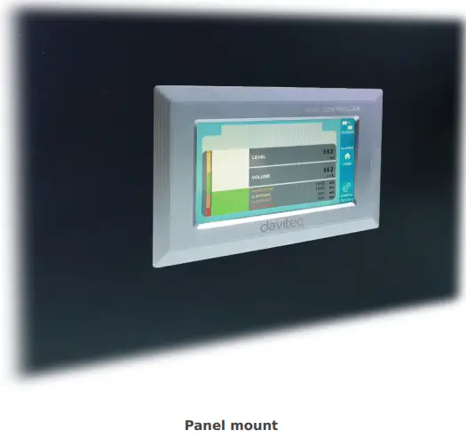
| Tipo di montaggio | Montaggio a pannello |
| Morsettiera | passo 5.0 mm, potenza nominale 300 V CA, dimensione filo 12-24 AWG |
| Temperatura / umidità di lavoro | 0..60 °C / 95% RH senza condensa |
| Dimensione | A93xL138xP45 |
| Peso netto | 390 grammi |
Immagini del prodotto


Principio di funzionamento

5.1 Comunicazione Modbus

02 x RS485/ModbusRTU-Slave
Protocollo: Modbus-RTU
Indirizzo: 1 – 247, 0 is the Broadcast address
Velocità in baud: 9600 , 19200
Parità: nessuno, dispari, pari
- LED indicatore di stato:
- Led on: modbus communication OK
- Led blinking: received data but modbus communication incorrect, due to wrong Modbus configuration: address, baudrate
- Led off: LFC128-2 received no data, check the connection
Registrazioni Memmap
READ utilizza il comando 03, WRITE utilizza il comando 16
Configurazione predefinita:
- Indirizzo: 1
- Baudrate slave 1: 9600
- Parity slave 1: none
- Baudrate slave 2: 9600
- Parity slave 2: none
| Registro Modbus | Hex adr | # of registers |
Descrizione | Allineare | Predefinito | Formato | Proprietà | Commento |
| 0 | 0 | 2 | informazioni sul dispositivo | LFC1 | corda | Leggere | ||
| 8 | 8 | 1 | DI1 DI2: digital status | 0-1 | Uint8 | Leggere | H_byte: DI1 L_byte: DI2 | |
| 9 | 9 | 1 | DI3 DI4: digital status | 0-1 | Uint8 | Leggere | H_byte: DI3 L_byte: DI4 | |
| 10 | A | 1 | AI1 AI2: digital status | 0-1 | Uint8 | Leggere | H_byte: AI1 L_byte: AI2 | |
| 11 | B | 1 | AI3 AI4: digital status | 0-1 | Uint8 | Leggere | H_byte: AI3 L_byte: AI4 | |
| 12 | C | 1 | AI1: valore analogico | Uint16 | Leggere | |||
| 13 | D | 1 | AI2: valore analogico | Uint16 | Leggere | |||
| 14 | E | 1 | AI3: valore analogico | Uint16 | Leggere | |||
| 15 | F | 1 | AI4: valore analogico | Uint16 | Leggere | |||
| 16 | 10 | 2 | AI1: valore scalato | galleggiante | Leggere | |||
| 18 | 12 | 2 | AI2: valore scalato | galleggiante | Leggere | |||
| 20 | 14 | 2 | AI3: valore scalato | galleggiante | Leggere | |||
| 22 | 16 | 2 | AI4: valore scalato | galleggiante | Leggere | |||
| 24 | 18 | 1 | relè 1 | 0-1 | Uint16 | Leggere | ||
| 25 | 19 | 1 | relè 2 | 0-1 | Uint16 | Leggere | ||
| 26 | 1A | 1 | relè 3 | 0-1 | Uint16 | Leggere | ||
| 27 | 1B | 1 | relè 4 | 0-1 | Uint16 | Leggere | ||
| 28 | 1C | 1 | controllo del collettore aperto | 0-3 | Uint16 | Leggere/scrivere | 0: spento 1: acceso 2: pwm, impulso continuo 3: impulso, quando il numero di impulsi è sufficiente, ctrl = 0 | |
| 30 | 1E | 2 | contatore DI1 | Uint32 | Leggere/scrivere | contatore scrivibile, cancellabile | ||
| 32 | 20 | 2 | contatore DI2 | Uint32 | Leggere/scrivere | contatore scrivibile, cancellabile | ||
| 34 | 22 | 2 | contatore DI3 | Uint32 | Leggere/scrivere | contatore scrivibile, cancellabile | ||
| 36 | 24 | 2 | contatore DI4 | Uint32 | Leggere/scrivere | contatore scrivibile, cancellabile | ||
| 38 | 26 | 2 | contatore AI1 | Uint32 | Leggere/scrivere | counter writable, erasable, max frequency 10Hz | ||
| 40 | 28 | 2 | contatore AI2 | Uint32 | Leggere/scrivere | counter writable, erasable, max frequency 10Hz | ||
| 42 | 2A | 2 | contatore AI3 | Uint32 | Leggere/scrivere | counter writable, erasable, max frequency 10Hz | ||
| 44 | 2C | 2 | contatore AI4 | Uint32 | Leggere/scrivere | counter writable, erasable, max frequency 10Hz | ||
| 46 | 2E | 2 | DI1: time on | Uint32 | Leggere/scrivere | secondo | ||
| 48 | 30 | 2 | DI2: time on | Uint32 | Leggere/scrivere | secondo | ||
| 50 | 32 | 2 | DI3: time on | Uint32 | Leggere/scrivere | secondo | ||
| 52 | 34 | 2 | DI4: time on | Uint32 | Leggere/scrivere | secondo | ||
| 54 | 36 | 2 | AI1: time on | Uint32 | Leggere/scrivere | secondo | ||
| 56 | 38 | 2 | AI2: time on | Uint32 | Leggere/scrivere | secondo | ||
| 58 | 3A | 2 | AI3: time on | Uint32 | Leggere/scrivere | secondo | ||
| 60 | 3C | 2 | AI4: time on | Uint32 | Leggere/scrivere | secondo | ||
| 62 | 3E | 2 | DI1: time off | Uint32 | Leggere/scrivere | secondo | ||
| 64 | 40 | 2 | DI2: time off | Uint32 | Leggere/scrivere | secondo | ||
| 66 | 42 | 2 | DI3: time off | Uint32 | Leggere/scrivere | secondo | ||
| 68 | 44 | 2 | DI4: time off | Uint32 | Leggere/scrivere | secondo | ||
| 70 | 46 | 2 | AI1: time off | Uint32 | Leggere/scrivere | secondo | ||
| 72 | 48 | 2 | AI2: time off | Uint32 | Leggere/scrivere | secondo | ||
| 74 | 4A | 2 | AI3: time off | Uint32 | Leggere/scrivere | secondo | ||
| 76 | 4C | 2 | AI4: time off | Uint32 | Leggere/scrivere | secondo | ||
| 128 | 80 | 2 | contatore DI1 | Uint32 | Leggere | il contatore non può scrivere, cancellare | ||
| 130 | 82 | 2 | contatore DI2 | Uint32 | Leggere | il contatore non può scrivere, cancellare | ||
| 132 | 84 | 2 | contatore DI3 | Uint32 | Leggere | il contatore non può scrivere, cancellare | ||
| 134 | 86 | 2 | contatore DI4 | Uint32 | Leggere | il contatore non può scrivere, cancellare | ||
| 136 | 88 | 2 | contatore AI1 | Uint32 | Leggere | il contatore non può scrivere, cancellare; frequenza massima 10Hz | ||
| 138 | 8A | 2 | contatore AI2 | Uint32 | Leggere | il contatore non può scrivere, cancellare; frequenza massima 10Hz | ||
| 140 | 8C | 2 | contatore AI3 | Uint32 | Leggere | il contatore non può scrivere, cancellare; frequenza massima 10Hz | ||
| 142 | 8E | 2 | contatore AI4 | Uint32 | Leggere | il contatore non può scrivere, cancellare; frequenza massima 10Hz | ||
| 256 | 100 | 1 | indirizzo modbus slave | 1-247 | 1 | Uint16 | Leggere/scrivere |
|
| 257 | 101 | 1 | velocità in baud modbus slave 1 | 0-1 | 0 | Uint16 | Leggere/scrivere |
0: 9600, 1: 19200 |
| 258 | 102 | 1 | slave di parità modbus 1 | 0-2 | 0 | Uint16 | Leggere/scrivere |
0: nessuno, 1: dispari, 2: pari |
5.2 Pulsante di ripristino
When holding the reset button for 4 seconds, LFC 128-2 will reset the default configuration to 02 x RS485 / Modbus
RTU-Slave.
Configurazione Modbus RTU predefinita:
- Indirizzo: 1
- Velocità in baud: 9600
- Parità: nessuna
5.3 Ingresso digitale

Specifica:
- 04 channels DI, isolated
- Input Resistance: 4.7 kΏ
- Volume di isolamentotage: 5000 Vrms
- Logic level 0: 0-1V
- Logic level 1: 5-24V
- Funzione:
- Read logic 0/1
- Contaimpulsi
5.3.1 Leggere lo stato logico 0/1
Valore logico nella mappa di memoria Modbus: 0-1
Registri per memorizzare i valori logici nella mappa di memoria Modbus:
- DI1__DI2: digital status: stores the logical state of channel 1 and channel 2.
H_byte: DI1
L_byte: DI2 - DI3__DI4: digital status: store the logical state of channel 3 and channel 4.
H_byte: DI3
L_byte: DI4
5.3.2 Contatore di impulsi
Valore del contatore nella mappa di memoria Modbus, quando l'aggiunta del numero supera la soglia, verrà restituito automaticamente: 0 4294967295 (32 bit)
Il registro che memorizza il valore del contatore nella mappa di memoria Modbus non può essere cancellato:
- Contatore DI1: memorizza lo stato logico del canale 1
- Contatore DI2: memorizza lo stato logico del canale 2
- Counter DI3: store the logic state of channel 3
- Contatore DI4: memorizza lo stato logico del canale 4
Il registro che memorizza il valore del contatore nella mappa di memoria Modbus non può essere cancellato: - None reset counter DI1: stores the logic state of channel 1
- None reset counter DI2: stores the logic state of channel 2
- None reset counter DI3: stores the logic state of channel 3
- None reset counter DI4: stores the logic state of channel 4
Pulse Counter Mode:
Low-speed pulse count less than 10Hz with filter, anti-jamming:
- Set register “counter DI1: filter time” = 500-2000: Channel 1 counts pulses less than 10Hz
- Set register “counter DI2: filter time” = 500-2000: Channel 2 counts pulses less than 10Hz
- Set register “counter DI3: filter time” = 500-2000: Channel 3 counts pulses less than 10Hz
- Set register “counter DI4: filter time” = 500-2000: Channel 4 counts pulses less than 10Hz
- High-speed pulse count with max 2KHz frequency without filter:
- Set register “counter DI1: filter time” = 1: channel 1 counts pulses with Fmax = 2kHz
- Set register “counter DI2: filter time” = 1: channel 2 counts pulses with Fmax = 2kHz
- Set register “counter DI3: filter time” = 1: channel 3 counts pulses with Fmax = 2kHz
- Set register “counter DI4: filter time” = 1: channel 4 counts pulses with Fmax = 2kHz
5.4 Ingresso analogico
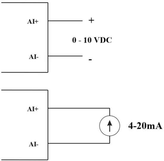
04 canali AI, nessun isolamento (AI1 è un ingresso sensore di livello 4-20 mA / 0-5 VDC / 0-10 VDC)
Utilizzare il DIP SW per configurare l'ingresso analogico: 0-10 V, 0-20 mA
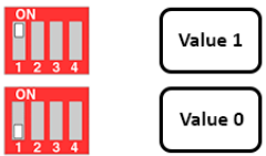
| Valore | Type of AI |
| 0 | 0-10 V |
| 1 | 0-20 mA |
Tipo di input:
- Misura volumetage: 0-10 V
- Measure current: 0-20mA
- The configuration for AI reads the same logical state as DI, but it is not isolated with a pulse range of 0-24V
Impedenza di ingresso:
- Misura volumetage: 320 kΏ
- Measure the current: 499 Ώ
5.4.1 Leggere il valore analogico
Risoluzione 12 bit
Non linearità: 0.1%
Valore analogico nella mappa di memoria Modbus: 0-3900
Registro dei valori analogici nella mappa di memoria Modbus:
- AI1 analog value: store the Analog value of channel 1
- AI2 analog value: stores the Analog value of channel 2
- AI3 analog value: store the Analog value of channel 3
- AI4 analog value: store the Analog value of channel 4
5.4.2 La configurazione AI funziona come DI
Nessun isolamento
AI Configura l'IA per leggere lo stesso stato logico di DI con impulso amptensione da 0-24V
Ci sono 2 soglie di conteggio AIx: soglia logica 0 e conteggio AIx: soglia logica 1 nella tabella modbus: 0-4095
- Analog Analog value of AI <counter AIx: threshold logic 0: is considered Logic 0 status of AI
- Analog Analog value of AI> counter AIx: threshold logic 1: is considered to be Logic 1 state of AI
- Counter AIx: threshold logic 0 = <Analog value of AI <= counter AIx: threshold logic 1: is considered to be the constant logic state
Logica Valore di stato logico dell'IA nella tabella della mappa di memoria Modbus: 0-1
Il registro memorizza i valori logici nella mappa di memoria Modbus:
- AI1___AI2: digital status: stores the logical state of channel 1 and channel 2.
H_byte: AI1
L_byte: AI2 - AI3___AI4: digital status: stores the logical state of channel 1 and channel 2.
H_byte: AI3
L_byte: AI4
5.4.3 Contatore di impulsi AI max 10Hz
Valore del contatore nella mappa di memoria Modbus, quando si aggiunge il numero oltre la soglia, verrà restituito automaticamente: 0 4294967295 (32 bit)
Il registro che memorizza il valore del contatore nella mappa di memoria Modbus non può essere cancellato:
- Counter AI1: stores the logic state of channel 1
- Counter AI2: save logic state of channel 2
- Counter AI3: save logic state of channel 3
- Counter AI4: save logic state of channel 4
Il registro che memorizza il valore del contatore nella mappa di memoria Modbus non può essere cancellato: - None reset counter AI1: stores the logic state of channel 1
- None reset counter AI2: stores the logic state of channel 2
- None reset counter AI3: stores the logic state of channel 3
- None reset counter AI4: save logic state of channel 4
Relè 5.5
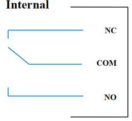
04 channel Relay SPDT NO / NC
Contact rating: 2A / 24VDC, 0.5A / 220VAC
There are status LEDs:
- Led on: Close Contact
- Led off: Open Contact
| Registro di relè predefinito | Status of relays when resetting power supplies |
| 3 | Operate according to the Alarm configuration |
Configurazione allarme:
- HIHI : Relay 4 On
- HI : Relay 3 On
- LO : Relay 2 On
- LOLO: Relay 1 On
5.6 Uscita a impulsi

01 isolated open-collector channel
Opto-coupler: Source current Imax = 10mA, Vceo = 80V
Funzioni: On / Off, pulse generator, PWM
5.6.1 Funzione On/Off
Set the Open-collector register in the Modbus Memory Map table:
- Set Open-collector register: 1 => Pulse Output ON
- Set Open-collector register: 0 => Pulse Output OFF
5.6.2 Generatore di impulsi
L'uscita a impulsi trasmette un massimo di 65535 impulsi, con Fmax 2.5 kHz
Configurare i seguenti registri nella tabella Modbus Memory Map:
- Set register “open collector: pulse number”: 0-65535 => Pulse Number = 65535: broadcast 65535 pulses
- Set register “open collector: time cycle”: (0-65535) x0.1ms => Time Cycle = 4: Fmax 2.5kHz
- Set register “open collector: time on”: (0-65535) x0.1ms => Time On: is the logic time 1 of the pulse
- Set the register “open collector ctrl” = 3 => configure the Pulse Output to generate a pulse and start to pulse, generate a sufficient number of pulses in the “open collector: pulse number” register => stop pulse generator and register ” open collector ctrl ”= 0
5.6.3 PWM
Frequenza massima 2.5 kHz
Configurare i seguenti registri nella tabella Modbus Memory Map:
- Set the register “open collector ctrl” = 2 => configure Pulse Output PWM function
- Set register “open collector: time cycle”: (0-65535) x0.1ms => Time Cycle = 4: Fmax 2.5kHz
- Set register “open collector: time on”: (0-65535) x0.1ms => Time On: is the logic time 1 of the pulse
Installazione
6.1 Metodo di installazione
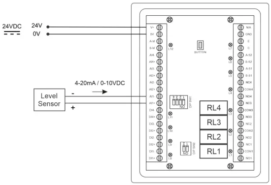
 6.2 Cablaggio con sensore di livello

Configurazione
7.1 Home Screen

SCHERMO: Switch to 2nd screen with more detailed information
ALLARMI: Show Level Alert
CASA: Torna alla schermata iniziale
CONFIG. (Default Password: a): Go to Setting Screen
7.2 Schermata di impostazione (Password predefinita: a)
7.2.1 Schermo 1
![daviteq LFC128 2 Advanced Level Display Controller - Home Screen 1] '](https://manuals.plus/wp-content/uploads/2025/08/daviteq-LFC128-2-Advanced-Level-Display-Controller-Home-Screen-1-550x305.png)
ADC: Raw signal value of channel AI1
Level (Unit): The level corresponds to the ADC signal after configuration
Decimal Places Level:Decimal number of digits after the dot of Level 0-3 (00000, 1111.1, 222.22, 33.333)
Unit level: level units, 0-3 (0: mm, 1: cm, 2: m, 3: inch)
Nel 1: Enter the ADC value after putting 4 mA / 0 VDC into AI1 for calibration at 0 level
Scala 1: The level value displayed corresponds to the value entered in In 1 (usually 0)
Nel 2: Enter the ADC value after putting 20 mA / 10 VDC into AI1 for calibration at Full level
Scala 2: The level value displayed corresponds to the value entered in In 2
Span Level: Maximum value of Level (Span Level ≥ Scale 2)
Decimal Places Volume: Decimal number of digits after the dot of Volume 0-3 (00000, 1111.1, 222.22, 33.333)
Unit Volume: units of volume 0-3 (0: lit, 1: cm, 2: m3, 3:%)
7.2.2 Schermo 2

Level Hi Hi Set point (Unit): High High level of Alarm Level
Level Hi Hi Hys (Unit): High High level hysteresis of Alarm Level
Level Hi Set point (Unit): High level of Alarm Level
Level Hi Hys (Unit): High level hysteresis of Alarm Level
Level Lo Set point (Unit): Low level of Alarm Level
Level Lo Hys (Unit): Low level hysteresis of Alarm Level
Level Lo Lo Set point (Unit): Low Low level of Alarm Level
Level Lo Lo Hys (Unit): Low Low level hysteresis of Alarm Level
Modalità sveglia: 0: Level, 1: Volume
Span Volume(Unit): Maximum value of the volume
7.2.3 Schermo 3

Volume Hi Hi Set point (Unit): High High volume of Alarm Volume
Volume Hi Hi Hys (Unit): High High volume hysteresis of Alarm Volume
Volume Hi Set point (Unit): High volume of Alarm Volume
Volume Hi Hys (Unit): High volume hysteresis of Alarm Volume
Volume Lo Set point (Unit): Low volume of Alarm Volume
Volume Lo Hys (Unit): Low volume hysteresis of Alarm Volume
Volume Lo Lo Set point (Unit): Low Low volume of Alarm Volume
Volume Lo Lo Hys (Unit): Low Low volume hysteresis of Alarm Volume
Run Total: Run the total function. 0-1 (0: No 1: Yes)
7.2.4 Schermo 4

Filling (Unit): Total function: total put into tank
Consumption (Unit): Total function: total consumption of the tank
Decimal Places Total: Decimal number of parameters Filling, Consumption, NRT Filling, NRT Consumption on display page (not the setting page)
Delta Total (Unit): Hysteresis level of the total function
Indirizzo Modbus: Modbus address of LFC128-2, 1-247
Modbus Baurate S1: 0-1 (0 : 9600 , 1 : 19200)
Modbus Parity S1: 0-2 (0: none, 1: odd, 2: even)
Modbus Baurate S2: 0-1 (0 : 9600 , 1 : 19200)
Modbus Parity S2: 0-2 (0: none, 1: odd, 2: even)
Num of Points: Number of points in the table to convert from level to volume, 1-166
7.2.5 Schermo 5

Point 1 Level (Level Unit): Level at Point 1
Point 1 Volume (Volume Unit): The corresponding volume at Point 1
Point 166 Level (Level Unit): Fuel level at Point 166
Point 166 Volume (Volume Unit): The corresponding volume at Point 166
7.2.6 Schermo 6

Password: Password to enter the Setting page, 8 ASCII characters
Tank Name: Tank name displayed on the main screen
Risoluzione dei problemi
| NO. | Fenomeni | Motivo | Soluzioni |
| 1 | Modbus non è riuscito a comunicare | Modbus LED Status: LED is off: received no data LED is blinking: the Modbus configuration is not the correct | Controllare la connessione Controllare la configurazione Modbus: indirizzo, velocità in baud, parità |
| 2 | Modbus fuori tempo massimo | Si sente rumore sulla linea | Configurare Baudrate 9600 e utilizzare un cavo a doppino intrecciato con protezione anti-jamming |
| 3 | Sensore disconnesso | Il sensore e l'LFC128 hanno perso la connessione | Checking connection Check sensor type (LFC128-2 only connects to 0-10VDC / 4- 20mA analog sensor type) Check the switch to see if it is turned on correctly Check that the sensor connector is correct AI1 |
| 4 | Errore della tabella di linearizzazione | Errore nella tabella di conversione da livello a volume | Controllare la configurazione della tabella di conversione da livello a volume |
Contatti di assistenza
Produttore
Daviteq Technologies Inc
No.11 Street 2G, Nam Hung Vuong Res., An Lac Ward, Binh Tan Dist., Ho Chi Minh City, Vietnam.
Tel: +84-28-6268.2523/4 (ext.122)
E-mail: info@daviteq.com
www.daviteq.com
Documenti / Risorse
 |
Controller di visualizzazione di livello avanzato daviteq LFC128-2 [pdf] Manuale di istruzioni LFC128-2, LFC128-2 Controller di visualizzazione di livello avanzato, Controller di visualizzazione di livello avanzato, Controller di visualizzazione di livello, Controller di visualizzazione |