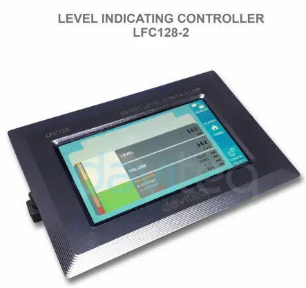
![]() Level Indicating
Level Indicating
Controller LFC128-2
UPORABNIŠKI NAVODILA ZA KRMILNIK NIVOJA LFC128-2
LFC128-2-MN-EN-01 JUN-2020
Napredni krmilnik zaslona LFC128-2
Ta dokument se uporablja za naslednje izdelke
| SKU | LFC128-2 | HW Ver. | 1.0 | FW Ver. | 1.1 |
| Šifra artikla | LFC128-2 | Krmilnik nivoja, 4AI/DI, 4DI, 4x rele, 1x impulzni izhod, 2 x RS485/ModbusRTU-Slave komunikacija | |||
Funkcije Dnevnik sprememb
| HW Ver. | FW Ver. | Datum izdaje | Funkcije spremeniti |
| 1.0 | 1.1 | JUN-2020 | |
Uvod
LFC128-2 je napredni krmilnik zaslona. Izdelek ima integriran vmesnik Modbus RTU, ki omogoča povezavo PLC / SCADA / BMS in katerega koli IoT vhoda z monitorjem. LFC128-2 ima preprosto, a zmogljivo zasnovo s 4 AI / DI, 4 DI, 4 releji, 1 impulznim impulznim izhodom in 2 RS485 podrejenima ModbusRTU-jema, kar omogoča enostavno povezavo z več napravami. Z napredno tehnologijo, ki zagotavlja visoko stabilnost in zanesljivost, številne funkcije, enostavno namestitev z zaslonom na dotik in prijaznim vmesnikom omogoča vizualno spremljanje nivoja.
Specifikacija
| Digitalni vhodi | 04 x Ports, opto-coupler, 4.7 kohms input resisrtance, 5000V rms isolation, Logic 0 (0-1VDC), Logic 1 (5-24VDC), Functions: logic status 0/1 or Pulse counting (32 bit counter with max 4kHz pulse) |
| Analogni vhodi | 04 x Ports, select between 0-10VDC input or 0-20mA input, 12 bit Resolution, can be configured as Digital input by DIP switch (max 10VDC input) The AI1 port is a 0-10 VDC / 4-20 mA level sensor connection port |
| Relejni izhod | 04 x Ports, electro-mechanical Relays, SPDT, contact rating 24VDC/2A or 250VAC/5A, LED indicators |
| Impulzni izhod | 01 x Ports, open-collector, opto-isolation, max 10mA and 80VDC, On/off control, Pulser (max 2.5Khz, max 65535 Pulses) or PWM (max 2.5Khz) |
| Komunikacija | 02 x ModbusRTU-Slave, RS485, hitrost 9600 ali 19200, LED indikator |
| Gumb za ponastavitev | For resetting 02 x RS485 Slave port to default setting (9600, None parity, 8 bit) |
| Vrsta zaslona | Zaslon na dotik |
| Napajanje | 9..36 VDC |
| Poraba | 200 mA pri napajanju 24 VDC |
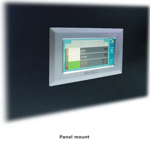
| Vrsta montaže | Montaža na ploščo |
| Terminalni blok | korak 5.0 mm, nazivna napetost 300 VAC, velikost žice 12-24 AWG |
| Delovna temperatura / vlažnost | 0..60 °C / 95 % relativne vlažnosti brez kondenzacije |
| Dimenzija | V93xŠ138xD45 |
| Neto teža | 390 gramov |
Slike izdelkov


Načelo delovanja

5.1 Modbus komunikacija

02 x RS485/ModbusRTU-Slave
Protokol: Modbus RTU
Naslov: 1 – 247, 0 is the Broadcast address
Hitrost prenosa: 9600, 19200
Parnost: nič, liho, sodo
- LED indikator stanja:
- Led on: modbus communication OK
- Led blinking: received data but modbus communication incorrect, due to wrong Modbus configuration: address, baudrate
- Led off: LFC128-2 received no data, check the connection
Memmap se registrira
BRANJE uporablja ukaz 03, PISANJE pa ukaz 16.
Privzeta konfiguracija:
- Naslov: 1
- Baudrate slave 1: 9600
- Parity slave 1: none
- Baudrate slave 2: 9600
- Parity slave 2: none
| Register Modbus | Hex adr | # of registers |
Opis | Razpon | Privzeto | Oblika | Lastnina | Komentiraj |
| 0 | 0 | 2 | informacije o napravi | LFC1 | niz | Preberi | ||
| 8 | 8 | 1 | DI1 DI2: digital status | 0-1 | uint8 | Preberi | H_bajt: DI1 L_bajt: DI2 | |
| 9 | 9 | 1 | DI3 DI4: digital status | 0-1 | uint8 | Preberi | H_bajt: DI3 L_bajt: DI4 | |
| 10 | A | 1 | AI1 AI2: digital status | 0-1 | uint8 | Preberi | H_bajt: AI1 L_bajt: AI2 | |
| 11 | B | 1 | AI3 AI4: digital status | 0-1 | uint8 | Preberi | H_bajt: AI3 L_bajt: AI4 | |
| 12 | C | 1 | AI1: analogna vrednost | uint16 | Preberi | |||
| 13 | D | 1 | AI2: analogna vrednost | uint16 | Preberi | |||
| 14 | E | 1 | AI3: analogna vrednost | uint16 | Preberi | |||
| 15 | F | 1 | AI4: analogna vrednost | uint16 | Preberi | |||
| 16 | 10 | 2 | AI1: skalirana vrednost | lebdi | Preberi | |||
| 18 | 12 | 2 | AI2: skalirana vrednost | lebdi | Preberi | |||
| 20 | 14 | 2 | AI3: skalirana vrednost | lebdi | Preberi | |||
| 22 | 16 | 2 | AI4: skalirana vrednost | lebdi | Preberi | |||
| 24 | 18 | 1 | rele 1 | 0-1 | uint16 | Preberi | ||
| 25 | 19 | 1 | rele 2 | 0-1 | uint16 | Preberi | ||
| 26 | 1A | 1 | rele 3 | 0-1 | uint16 | Preberi | ||
| 27 | 1B | 1 | rele 4 | 0-1 | uint16 | Preberi | ||
| 28 | 1C | 1 | odprti kolektorski nadzor | 0-3 | uint16 | Branje/Pisanje | 0: izklopljeno 1: vklopljeno 2: pwm, neprekinjeno pulziranje 3: pulziranje, ko je dovolj pulzov, krmiljenje = 0 | |
| 30 | 1E | 2 | števec DI1 | uint32 | Branje/Pisanje | števec, ki ga je mogoče zapisovati, izbrisati | ||
| 32 | 20 | 2 | števec DI2 | uint32 | Branje/Pisanje | števec, ki ga je mogoče zapisovati, izbrisati | ||
| 34 | 22 | 2 | števec DI3 | uint32 | Branje/Pisanje | števec, ki ga je mogoče zapisovati, izbrisati | ||
| 36 | 24 | 2 | števec DI4 | uint32 | Branje/Pisanje | števec, ki ga je mogoče zapisovati, izbrisati | ||
| 38 | 26 | 2 | števec AI1 | uint32 | Branje/Pisanje | counter writable, erasable, max frequency 10Hz | ||
| 40 | 28 | 2 | števec AI2 | uint32 | Branje/Pisanje | counter writable, erasable, max frequency 10Hz | ||
| 42 | 2A | 2 | števec AI3 | uint32 | Branje/Pisanje | counter writable, erasable, max frequency 10Hz | ||
| 44 | 2C | 2 | števec AI4 | uint32 | Branje/Pisanje | counter writable, erasable, max frequency 10Hz | ||
| 46 | 2E | 2 | DI1: time on | uint32 | Branje/Pisanje | sek | ||
| 48 | 30 | 2 | DI2: time on | uint32 | Branje/Pisanje | sek | ||
| 50 | 32 | 2 | DI3: time on | uint32 | Branje/Pisanje | sek | ||
| 52 | 34 | 2 | DI4: time on | uint32 | Branje/Pisanje | sek | ||
| 54 | 36 | 2 | AI1: time on | uint32 | Branje/Pisanje | sek | ||
| 56 | 38 | 2 | AI2: time on | uint32 | Branje/Pisanje | sek | ||
| 58 | 3A | 2 | AI3: time on | uint32 | Branje/Pisanje | sek | ||
| 60 | 3C | 2 | AI4: time on | uint32 | Branje/Pisanje | sek | ||
| 62 | 3E | 2 | DI1: time off | uint32 | Branje/Pisanje | sek | ||
| 64 | 40 | 2 | DI2: time off | uint32 | Branje/Pisanje | sek | ||
| 66 | 42 | 2 | DI3: time off | uint32 | Branje/Pisanje | sek | ||
| 68 | 44 | 2 | DI4: time off | uint32 | Branje/Pisanje | sek | ||
| 70 | 46 | 2 | AI1: time off | uint32 | Branje/Pisanje | sek | ||
| 72 | 48 | 2 | AI2: time off | uint32 | Branje/Pisanje | sek | ||
| 74 | 4A | 2 | AI3: time off | uint32 | Branje/Pisanje | sek | ||
| 76 | 4C | 2 | AI4: time off | uint32 | Branje/Pisanje | sek | ||
| 128 | 80 | 2 | števec DI1 | uint32 | Preberi | števec ne more pisati, brisati | ||
| 130 | 82 | 2 | števec DI2 | uint32 | Preberi | števec ne more pisati, brisati | ||
| 132 | 84 | 2 | števec DI3 | uint32 | Preberi | števec ne more pisati, brisati | ||
| 134 | 86 | 2 | števec DI4 | uint32 | Preberi | števec ne more pisati, brisati | ||
| 136 | 88 | 2 | števec AI1 | uint32 | Preberi | števec ne more pisati, brisati; najvišja frekvenca 10 Hz | ||
| 138 | 8A | 2 | števec AI2 | uint32 | Preberi | števec ne more pisati, brisati; najvišja frekvenca 10 Hz | ||
| 140 | 8C | 2 | števec AI3 | uint32 | Preberi | števec ne more pisati, brisati; najvišja frekvenca 10 Hz | ||
| 142 | 8E | 2 | števec AI4 | uint32 | Preberi | števec ne more pisati, brisati; najvišja frekvenca 10 Hz | ||
| 256 | 100 | 1 | podrejeni naslov Modbus | 1-247 | 1 | uint16 | Branje/Pisanje |
|
| 257 | 101 | 1 | podrejeni modul 1 s hitrostjo prenosa Modbus | 0-1 | 0 | uint16 | Branje/Pisanje |
0:9600, 1:19200 |
| 258 | 102 | 1 | podrejeni paritetni Modbus 1 | 0-2 | 0 | uint16 | Branje/Pisanje |
0: nič, 1: liho, 2: sodo |
5.2 Gumb za ponastavitev
When holding the reset button for 4 seconds, LFC 128-2 will reset the default configuration to 02 x RS485 / Modbus
RTU-Slave.
Privzeta konfiguracija Modbus RTU:
- Naslov: 1
- Hitrost prenosa: 9600
- Pariteta: nobena
5.3 Digitalni vhod

Specifikacija:
- 04 channels DI, isolated
- Input Resistance: 4.7 kΏ
- Izolacija Voltage: 5000 Vrms
- Logic level 0: 0-1V
- Logic level 1: 5-24V
- Funkcija:
- Read logic 0/1
- Števec impulzov
5.3.1 Preberi logično stanje 0/1
Logična vrednost v pomnilniškem zemljevidu Modbus: 0–1
Registri za shranjevanje logičnih vrednosti v pomnilniški mapi Modbus:
- DI1__DI2: digital status: stores the logical state of channel 1 and channel 2.
H_byte: DI1
L_byte: DI2 - DI3__DI4: digital status: store the logical state of channel 3 and channel 4.
H_byte: DI3
L_byte: DI4
5.3.2 Števec impulzov
Vrednost števca v pomnilniškem zemljevidu Modbus. Ko seštevanje preseže prag, se samodejno vrne: 0 4294967295 (32 bitov)
Register, ki shranjuje vrednost števca v pomnilniškem zemljevidu Modbus, ni mogoče izbrisati:
- Števec DI1: shranjuje logično stanje kanala 1
- Števec DI2: shranjuje logično stanje kanala 2
- Counter DI3: store the logic state of channel 3
- Števec DI4: shranjuje logično stanje kanala 4
Register, ki shranjuje vrednost števca v pomnilniškem zemljevidu Modbus, ni mogoče izbrisati: - None reset counter DI1: stores the logic state of channel 1
- None reset counter DI2: stores the logic state of channel 2
- None reset counter DI3: stores the logic state of channel 3
- None reset counter DI4: stores the logic state of channel 4
Pulse Counter Mode:
Low-speed pulse count less than 10Hz with filter, anti-jamming:
- Set register “counter DI1: filter time” = 500-2000: Channel 1 counts pulses less than 10Hz
- Set register “counter DI2: filter time” = 500-2000: Channel 2 counts pulses less than 10Hz
- Set register “counter DI3: filter time” = 500-2000: Channel 3 counts pulses less than 10Hz
- Set register “counter DI4: filter time” = 500-2000: Channel 4 counts pulses less than 10Hz
- High-speed pulse count with max 2KHz frequency without filter:
- Set register “counter DI1: filter time” = 1: channel 1 counts pulses with Fmax = 2kHz
- Set register “counter DI2: filter time” = 1: channel 2 counts pulses with Fmax = 2kHz
- Set register “counter DI3: filter time” = 1: channel 3 counts pulses with Fmax = 2kHz
- Set register “counter DI4: filter time” = 1: channel 4 counts pulses with Fmax = 2kHz
5.4 Analogni vhod
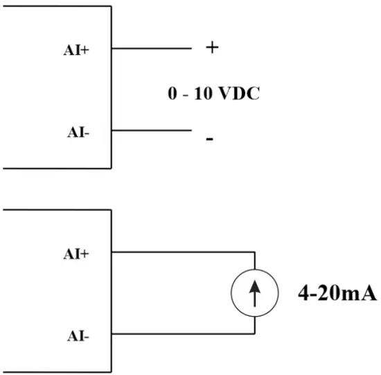
04 AI kanali, brez izolacije (AI1 je vhod za senzor nivoja 4–20 mA / 0–5 VDC / 0–10 VDC)
Z DIP preklopnikom konfigurirajte analogni vhod: 0–10 V, 0–20 mA
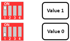
| Vrednost | Type of AI |
| 0 | 0-10 V |
| 1 | 0-20 mA |
Vrsta vnosa:
- Izmerite voltage: 0-10 V
- Measure current: 0-20mA
- The configuration for AI reads the same logical state as DI, but it is not isolated with a pulse range of 0-24V
Vhodna impedanca:
- Izmerite voltage: 320 kΏ
- Measure the current: 499 Ώ
5.4.1 Odčitavanje analogne vrednosti
Ločljivost 12 bitov
Nelinearnost: 0.1 %
Analogna vrednost v pomnilniškem zemljevidu Modbus: 0–3900
Register analognih vrednosti v pomnilniškem zemljevidu Modbus:
- AI1 analog value: store the Analog value of channel 1
- AI2 analog value: stores the Analog value of channel 2
- AI3 analog value: store the Analog value of channel 3
- AI4 analog value: store the Analog value of channel 4
5.4.2 Konfiguracija AI deluje kot DI
Brez izolacije
AI Konfigurirajte AI za branje istega logičnega stanja kot DI s pulziranjem ampsvetloba od 0 do 24 V
V tabeli Modbus: 2–0 sta 1 praga števca AIx: logični prag 0 in števec AIx: logični prag 4095.
- Analog Analog value of AI <counter AIx: threshold logic 0: is considered Logic 0 status of AI
- Analog Analog value of AI> counter AIx: threshold logic 1: is considered to be Logic 1 state of AI
- Counter AIx: threshold logic 0 = <Analog value of AI <= counter AIx: threshold logic 1: is considered to be the constant logic state
Logika Logična vrednost stanja AI v tabeli pomnilniškega zemljevida Modbus: 0–1
Register shrani logične vrednosti v pomnilniški mapi Modbus:
- AI1___AI2: digital status: stores the logical state of channel 1 and channel 2.
H_byte: AI1
L_byte: AI2 - AI3___AI4: digital status: stores the logical state of channel 1 and channel 2.
H_byte: AI3
L_byte: AI4
5.4.3 Števec impulzov AI maks. 10 Hz
Vrednost števca v pomnilniškem zemljevidu Modbus, ko seštejete število preko praga, se samodejno vrne: 0 4294967295 (32 bitov)
Register, ki shranjuje vrednost števca v pomnilniškem zemljevidu Modbus, ni mogoče izbrisati:
- Counter AI1: stores the logic state of channel 1
- Counter AI2: save logic state of channel 2
- Counter AI3: save logic state of channel 3
- Counter AI4: save logic state of channel 4
Register, ki shranjuje vrednost števca v pomnilniškem zemljevidu Modbus, ni mogoče izbrisati: - None reset counter AI1: stores the logic state of channel 1
- None reset counter AI2: stores the logic state of channel 2
- None reset counter AI3: stores the logic state of channel 3
- None reset counter AI4: save logic state of channel 4
5.5 Rele
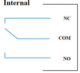
04 channel Relay SPDT NO / NC
Contact rating: 2A / 24VDC, 0.5A / 220VAC
There are status LEDs:
- Led on: Close Contact
- Led off: Open Contact
| Privzeti register releja | Status of relays when resetting power supplies |
| 3 | Operate according to the Alarm configuration |
Konfiguracija alarma:
- HIHI : Relay 4 On
- HI : Relay 3 On
- LO : Relay 2 On
- LOLO: Relay 1 On
5.6 Impulzni izhod

01 isolated open-collector channel
Opto-coupler: Source current Imax = 10mA, Vceo = 80V
Funkcije: On / Off, pulse generator, PWM
5.6.1 Funkcija vklopa/izklopa
Set the Open-collector register in the Modbus Memory Map table:
- Set Open-collector register: 1 => Pulse Output ON
- Set Open-collector register: 0 => Pulse Output OFF
5.6.2 Generator impulzov
Impulzni izhod oddaja največ 65535 impulzov z Fmax 2.5 kHz
V tabeli Modbus Memory Map konfigurirajte naslednje registre:
- Set register “open collector: pulse number”: 0-65535 => Pulse Number = 65535: broadcast 65535 pulses
- Set register “open collector: time cycle”: (0-65535) x0.1ms => Time Cycle = 4: Fmax 2.5kHz
- Set register “open collector: time on”: (0-65535) x0.1ms => Time On: is the logic time 1 of the pulse
- Set the register “open collector ctrl” = 3 => configure the Pulse Output to generate a pulse and start to pulse, generate a sufficient number of pulses in the “open collector: pulse number” register => stop pulse generator and register ” open collector ctrl ”= 0
5.6.3 PWM
Največja frekvenca 2.5 kHz
V tabeli Modbus Memory Map konfigurirajte naslednje registre:
- Set the register “open collector ctrl” = 2 => configure Pulse Output PWM function
- Set register “open collector: time cycle”: (0-65535) x0.1ms => Time Cycle = 4: Fmax 2.5kHz
- Set register “open collector: time on”: (0-65535) x0.1ms => Time On: is the logic time 1 of the pulse
Namestitev
6.1 Način namestitve
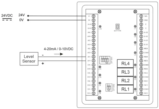
 6.2 Ožičenje s senzorjem nivoja

Konfiguracija
7.1 Začetni zaslon

ZASLON: Switch to 2nd screen with more detailed information
ALARMI: Show Level Alert
DOMOV: Vrnitev na začetni zaslon
KONFIG. (Default Password: a): Go to Setting Screen
7.2 Zaslon za nastavitve (privzeto geslo: a)
7.2.1 Zaslon 1
![daviteq LFC128 2 Advanced Level Display Controller - Home Screen 1] '](https://manuals.plus/wp-content/uploads/2025/08/daviteq-LFC128-2-Advanced-Level-Display-Controller-Home-Screen-1-550x305.png)
ADC-ji: Raw signal value of channel AI1
Level (Unit): The level corresponds to the ADC signal after configuration
Decimal Places Level:Decimal number of digits after the dot of Level 0-3 (00000, 1111.1, 222.22, 33.333)
Unit level: level units, 0-3 (0: mm, 1: cm, 2: m, 3: inch)
V 1: Enter the ADC value after putting 4 mA / 0 VDC into AI1 for calibration at 0 level
Lestvica 1: The level value displayed corresponds to the value entered in In 1 (usually 0)
V 2: Enter the ADC value after putting 20 mA / 10 VDC into AI1 for calibration at Full level
Lestvica 2: The level value displayed corresponds to the value entered in In 2
Span Level: Maximum value of Level (Span Level ≥ Scale 2)
Decimal Places Volume: Decimal number of digits after the dot of Volume 0-3 (00000, 1111.1, 222.22, 33.333)
Unit Volume: units of volume 0-3 (0: lit, 1: cm, 2: m3, 3:%)
7.2.2 Zaslon 2

Level Hi Hi Set point (Unit): High High level of Alarm Level
Level Hi Hi Hys (Unit): High High level hysteresis of Alarm Level
Level Hi Set point (Unit): High level of Alarm Level
Level Hi Hys (Unit): High level hysteresis of Alarm Level
Level Lo Set point (Unit): Low level of Alarm Level
Level Lo Hys (Unit): Low level hysteresis of Alarm Level
Level Lo Lo Set point (Unit): Low Low level of Alarm Level
Level Lo Lo Hys (Unit): Low Low level hysteresis of Alarm Level
Način alarma: 0: Level, 1: Volume
Span Volume(Unit): Maximum value of the volume
7.2.3 Zaslon 3

Volume Hi Hi Set point (Unit): High High volume of Alarm Volume
Volume Hi Hi Hys (Unit): High High volume hysteresis of Alarm Volume
Volume Hi Set point (Unit): High volume of Alarm Volume
Volume Hi Hys (Unit): High volume hysteresis of Alarm Volume
Volume Lo Set point (Unit): Low volume of Alarm Volume
Volume Lo Hys (Unit): Low volume hysteresis of Alarm Volume
Volume Lo Lo Set point (Unit): Low Low volume of Alarm Volume
Volume Lo Lo Hys (Unit): Low Low volume hysteresis of Alarm Volume
Run Total: Run the total function. 0-1 (0: No 1: Yes)
7.2.4 Zaslon 4

Filling (Unit): Total function: total put into tank
Consumption (Unit): Total function: total consumption of the tank
Decimal Places Total: Decimal number of parameters Filling, Consumption, NRT Filling, NRT Consumption on display page (not the setting page)
Delta Total (Unit): Hysteresis level of the total function
Modbus naslov: Modbus address of LFC128-2, 1-247
Modbus Baurate S1: 0-1 (0 : 9600 , 1 : 19200)
Modbus Parity S1: 0-2 (0: none, 1: odd, 2: even)
Modbus Baurate S2: 0-1 (0 : 9600 , 1 : 19200)
Modbus Parity S2: 0-2 (0: none, 1: odd, 2: even)
Num of Points: Number of points in the table to convert from level to volume, 1-166
7.2.5 Zaslon 5

Point 1 Level (Level Unit): Level at Point 1
Point 1 Volume (Volume Unit): The corresponding volume at Point 1
Point 166 Level (Level Unit): Fuel level at Point 166
Point 166 Volume (Volume Unit): The corresponding volume at Point 166
7.2.6 Zaslon 6

geslo: Password to enter the Setting page, 8 ASCII characters
Tank Name: Tank name displayed on the main screen
Odpravljanje težav
| št. | Fenomeni | Razlog | Rešitve |
| 1 | Komunikacija z Modbusom ni uspela | Modbus LED Status: LED is off: received no data LED is blinking: the Modbus configuration is not the correct | Preverite povezavo. Preverite konfiguracijo Modbusa: naslov, hitrost prenosa v baudih, pariteto. |
| 2 | Časovna omejitev Modbus | Na liniji se pojavi šum | Konfigurirajte Baudrate 9600 in uporabite zasukani par z zaščito pred motenjem |
| 3 | Senzor je odklopljen | Senzor in LFC128 sta izgubila povezavo | Checking connection Check sensor type (LFC128-2 only connects to 0-10VDC / 4- 20mA analog sensor type) Check the switch to see if it is turned on correctly Check that the sensor connector is correct AI1 |
| 4 | Napaka tabele linearizacije | Napaka pretvorbene tabele iz nivoja v volumen | Preverite konfiguracijo pretvorbene tabele iz ravni v prostornino |
Kontakti za podporo
Proizvajalec
Daviteq Technologies Inc
No.11 Street 2G, Nam Hung Vuong Res., An Lac Ward, Binh Tan Dist., Ho Chi Minh City, Vietnam.
Tel: +84-28-6268.2523/4 (ext.122)
E-pošta: info@daviteq.com
www.daviteq.com
Dokumenti / Viri
 |
daviteq LFC128-2 krmilnik zaslona napredne ravni [pdf] Navodila za uporabo LFC128-2, LFC128-2 krmilnik zaslona napredne ravni, krmilnik zaslona napredne ravni, krmilnik zaslona ravni, krmilnik zaslona |