![]() ការចង្អុលបង្ហាញកម្រិត
ការចង្អុលបង្ហាញកម្រិត
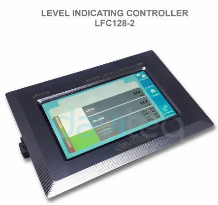
ឧបករណ៍បញ្ជា LFC128-2
មគ្គុទ្ទេសក៍អ្នកប្រើប្រាស់សម្រាប់កម្រិតបង្ហាញអ្នកត្រួតពិនិត្យ LFC128-2
LFC128-2-MN-EN-01 ខែមិថុនា-2020
LFC128-2 ឧបករណ៍បញ្ជាការបង្ហាញកម្រិតកម្រិតខ្ពស់
ឯកសារនេះត្រូវបានអនុវត្តសម្រាប់ផលិតផលខាងក្រោម
| SKU | LFC128-2 | HW Ver. | 1.0 | FW Ver. | 1.1 |
| លេខកូដធាតុ | LFC128-2 | ឧបករណ៍បញ្ជាកម្រិតបង្ហាញ, 4AI/DI, 4DI, 4xRelay, 1xPulse Output, 2 x RS485/ModbusRTU-Slave Communication | |||
មុខងារផ្លាស់ប្តូរកំណត់ហេតុ
| HW Ver. | FW Ver. | កាលបរិច្ឆេទចេញផ្សាយ | មុខងារ ផ្លាស់ប្តូរ |
| 1.0 | 1.1 | ខែមិថុនា-2020 | |
សេចក្តីផ្តើម
LFC128-2 គឺជាឧបករណ៍បញ្ជាការបង្ហាញកម្រិតកម្រិតខ្ពស់។ ផលិតផលរួមបញ្ចូលចំណុចប្រទាក់ Modbus RTU ដើម្បីជួយ PLC / SCADA / BMS និងច្រក IoT ណាមួយអាចភ្ជាប់ទៅម៉ូនីទ័រ។ LFC128-2 មានការរចនាដ៏សាមញ្ញ ប៉ុន្តែមានថាមពលជាមួយនឹង 4 AI / DI, 4 DI, 4 Relays, 1 Pulse pulse output, 2 RS485 Slave ModbusRTU អនុញ្ញាតឱ្យពួកវាភ្ជាប់ជាមួយឧបករណ៍ច្រើនយ៉ាងងាយស្រួល។ ជាមួយនឹងបច្ចេកវិជ្ជាទំនើបដែលផ្តល់នូវស្ថេរភាពនិងភាពជឿជាក់ខ្ពស់ មុខងារជាច្រើន ការដំឡើងងាយស្រួលជាមួយនឹងអេក្រង់ប៉ះ និងចំណុចប្រទាក់មិត្តភាពជួយឱ្យកម្រិតត្រួតពិនិត្យមើលឃើញ។
ការបញ្ជាក់
| ការបញ្ចូលឌីជីថល | 04 x Ports, opto-coupler, 4.7 kohms input resisrtance, 5000V rms isolation, Logic 0 (0-1VDC), Logic 1 (5-24VDC), មុខងារ៖ ស្ថានភាពតក្កវិជ្ជា 0/1 ឬការរាប់ជីពចរ (ការរាប់ 32 ប៊ីតជាមួយនឹងជីពចរអតិបរមា 4kHz) |
| ការបញ្ចូលអាណាឡូក | ច្រក 04 x ជ្រើសរើសរវាង 0-10VDC input ឬ 0-20mA input, 12 bit Resolution, can be configured as Digital input by DIP switch (max 10VDC input) ច្រក AI1 គឺជាច្រកតភ្ជាប់ឧបករណ៍ចាប់សញ្ញាកម្រិត 0-10 VDC / 4-20 mA |
| ទិន្នផលបញ្ជូនត | ច្រក 04 x, ការបញ្ជូនតអេឡិចត្រូមេកានិក, SPDT, ការវាយតម្លៃទំនាក់ទំនង 24VDC/2A ឬ 250VAC/5A, សូចនាករ LED |
| លទ្ធផលនៃជីពចរ | 01 x Ports, open-collector, opto-isolation, max 10mA និង 80VDC, បើក/off control, Pulser (max 2.5Khz, max 65535 Pulses) ឬ PWM (max 2.5Khz) |
| ទំនាក់ទំនង | 02 x ModbusRTU-Slave, RS485, ល្បឿន 9600 ឬ 19200, សូចនាករ LED |
| ប៊ូតុងកំណត់ឡើងវិញ | សម្រាប់ការកំណត់ឡើងវិញ 02 x RS485 Slave port ទៅជាការកំណត់លំនាំដើម (9600, None parity, 8 bit) |
| ប្រភេទអេក្រង់ | អេក្រង់ប៉ះ |
| ការផ្គត់ផ្គង់ថាមពល | 9..36VDC |
| ការប្រើប្រាស់ | ការផ្គត់ផ្គង់ 200mA @ 24VDC |
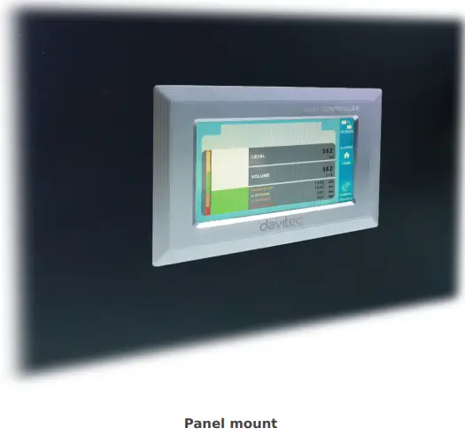
| ប្រភេទម៉ោន | បន្ទះម៉ោន |
| ប្លុកស្ថានីយ | កម្រិត 5.0mm, កម្រិត 300VAC, ទំហំខ្សែ 12-24AWG |
| សីតុណ្ហភាពការងារ / សំណើម | 0..60 degC / 95% RH មិនខាប់ |
| វិមាត្រ | H93xW138xD45 |
| ទំងន់សុទ្ធ | ២១៩ ក្រាម។ |
រូបភាពផលិតផល


គោលការណ៍ប្រតិបត្តិការ

5.1 ការទំនាក់ទំនង Modbus

02 x RS485/ModbusRTU-Slave
ពិធីសារៈ Modbus RTU
អាស័យដ្ឋាន៖ 1 – 247, 0 គឺជាអាសយដ្ឋានផ្សាយ
អត្រា Baud: ៣, ១
ភាពស្មើគ្នា: គ្មាន, សេស, គូ
- សូចនាករស្ថានភាព LED៖
- ដឹកនាំលើ៖ ការទំនាក់ទំនង modbus យល់ព្រម
- ពន្លឺភ្លឹបភ្លែតៗ៖ បានទទួលទិន្នន័យ ប៉ុន្តែការទំនាក់ទំនង modbus មិនត្រឹមត្រូវ ដោយសារការកំណត់រចនាសម្ព័ន្ធ Modbus ខុស៖ អាសយដ្ឋាន baudrate
- បិទ៖ LFC128-2 បានទទួលទិន្នន័យ ពិនិត្យការតភ្ជាប់
ចុះឈ្មោះ Memmap
អានប្រើពាក្យបញ្ជា 03, WRITE ប្រើពាក្យបញ្ជា 16
ការកំណត់រចនាសម្ព័ន្ធលំនាំដើម៖
- អាស័យដ្ឋាន៖ 1
- ទាសករ Baudrate 1: 9600
- ទាសករ Parity 1: គ្មាន
- ទាសករ Baudrate 2: 9600
- ទាសករ Parity 2: គ្មាន
| ចុះឈ្មោះ Modbus | Hex adr | # នៃការចុះឈ្មោះ |
ការពិពណ៌នា | ជួរ | លំនាំដើម | ទម្រង់ | ទ្រព្យសម្បត្តិ | មតិយោបល់ |
| 0 | 0 | 2 | ព័ត៌មានឧបករណ៍ | LFC1 | ខ្សែអក្សរ | អាន | ||
| 8 | 8 | 1 | ឌី២ DI2: ស្ថានភាពឌីជីថល | ០១៤៨៦០៧៤-០០៤ | uint8 | អាន | H_byte: DI1 L_byte: DI2 | |
| 9 | 9 | 1 | ឌី២ DI4: ស្ថានភាពឌីជីថល | ០១៤៨៦០៧៤-០០៤ | uint8 | អាន | H_byte: DI3 L_byte: DI4 | |
| 10 | A | 1 | AI២៤២ AI2: ស្ថានភាពឌីជីថល | ០១៤៨៦០៧៤-០០៤ | uint8 | អាន | H_byte: AI1 L_byte: AI2 | |
| 11 | B | 1 | AI២៤២ AI4: ស្ថានភាពឌីជីថល | ០១៤៨៦០៧៤-០០៤ | uint8 | អាន | H_byte: AI3 L_byte: AI4 | |
| 12 | C | 1 | AI1: តម្លៃអាណាឡូក | uint16 | អាន | |||
| 13 | D | 1 | AI2: តម្លៃអាណាឡូក | uint16 | អាន | |||
| 14 | E | 1 | AI3: តម្លៃអាណាឡូក | uint16 | អាន | |||
| 15 | F | 1 | AI4: តម្លៃអាណាឡូក | uint16 | អាន | |||
| 16 | 10 | 2 | AI1៖ តម្លៃមាត្រដ្ឋាន | អណ្តែត | អាន | |||
| 18 | 12 | 2 | AI2៖ តម្លៃមាត្រដ្ឋាន | អណ្តែត | អាន | |||
| 20 | 14 | 2 | AI3៖ តម្លៃមាត្រដ្ឋាន | អណ្តែត | អាន | |||
| 22 | 16 | 2 | AI4៖ តម្លៃមាត្រដ្ឋាន | អណ្តែត | អាន | |||
| 24 | 18 | 1 | បញ្ជូនត ១ | ០១៤៨៦០៧៤-០០៤ | uint16 | អាន | ||
| 25 | 19 | 1 | បញ្ជូនត ១ | ០១៤៨៦០៧៤-០០៤ | uint16 | អាន | ||
| 26 | 1A | 1 | បញ្ជូនត ១ | ០១៤៨៦០៧៤-០០៤ | uint16 | អាន | ||
| 27 | 1B | 1 | បញ្ជូនត ១ | ០១៤៨៦០៧៤-០០៤ | uint16 | អាន | ||
| 28 | 1C | 1 | បើកអ្នកប្រមូល ctrl | ០១៤៨៦០៧៤-០០៤ | uint16 | អាន/សរសេរ | 0: បិទ 1: នៅលើ 2: pwm, ជីពចរបន្ត 3: ជីពចរ, នៅពេលដែលចំនួនជីពចរគ្រប់គ្រាន់, ctrl = 0 | |
| 30 | 1E | 2 | ប្រឆាំង DI1 | uint32 | អាន/សរសេរ | អាចសរសេរបាន, អាចលុបបាន។ | ||
| 32 | 20 | 2 | ប្រឆាំង DI2 | uint32 | អាន/សរសេរ | អាចសរសេរបាន, អាចលុបបាន។ | ||
| 34 | 22 | 2 | ប្រឆាំង DI3 | uint32 | អាន/សរសេរ | អាចសរសេរបាន, អាចលុបបាន។ | ||
| 36 | 24 | 2 | ប្រឆាំង DI4 | uint32 | អាន/សរសេរ | អាចសរសេរបាន, អាចលុបបាន។ | ||
| 38 | 26 | 2 | ប្រឆាំង AI1 | uint32 | អាន/សរសេរ | រាប់អាចសរសេរបាន លុបបាន ប្រេកង់អតិបរមា 10Hz | ||
| 40 | 28 | 2 | ប្រឆាំង AI2 | uint32 | អាន/សរសេរ | រាប់អាចសរសេរបាន លុបបាន ប្រេកង់អតិបរមា 10Hz | ||
| 42 | 2A | 2 | ប្រឆាំង AI3 | uint32 | អាន/សរសេរ | រាប់អាចសរសេរបាន លុបបាន ប្រេកង់អតិបរមា 10Hz | ||
| 44 | 2C | 2 | ប្រឆាំង AI4 | uint32 | អាន/សរសេរ | រាប់អាចសរសេរបាន លុបបាន ប្រេកង់អតិបរមា 10Hz | ||
| 46 | 2E | 2 | DI1: ដល់ម៉ោងហើយ។ | uint32 | អាន/សរសេរ | វិ | ||
| 48 | 30 | 2 | DI2: ដល់ម៉ោងហើយ។ | uint32 | អាន/សរសេរ | វិ | ||
| 50 | 32 | 2 | DI3: ដល់ម៉ោងហើយ។ | uint32 | អាន/សរសេរ | វិ | ||
| 52 | 34 | 2 | DI4: ដល់ម៉ោងហើយ។ | uint32 | អាន/សរសេរ | វិ | ||
| 54 | 36 | 2 | AI1: ដល់ពេលហើយ។ | uint32 | អាន/សរសេរ | វិ | ||
| 56 | 38 | 2 | AI2: ដល់ពេលហើយ។ | uint32 | អាន/សរសេរ | វិ | ||
| 58 | 3A | 2 | AI3: ដល់ពេលហើយ។ | uint32 | អាន/សរសេរ | វិ | ||
| 60 | 3C | 2 | AI4: ដល់ពេលហើយ។ | uint32 | អាន/សរសេរ | វិ | ||
| 62 | 3E | 2 | DI1: សម្រាក | uint32 | អាន/សរសេរ | វិ | ||
| 64 | 40 | 2 | DI2: សម្រាក | uint32 | អាន/សរសេរ | វិ | ||
| 66 | 42 | 2 | DI3: សម្រាក | uint32 | អាន/សរសេរ | វិ | ||
| 68 | 44 | 2 | DI4: សម្រាក | uint32 | អាន/សរសេរ | វិ | ||
| 70 | 46 | 2 | AI1: សម្រាក | uint32 | អាន/សរសេរ | វិ | ||
| 72 | 48 | 2 | AI2: សម្រាក | uint32 | អាន/សរសេរ | វិ | ||
| 74 | 4A | 2 | AI3: សម្រាក | uint32 | អាន/សរសេរ | វិ | ||
| 76 | 4C | 2 | AI4: សម្រាក | uint32 | អាន/សរសេរ | វិ | ||
| 128 | 80 | 2 | ប្រឆាំង DI1 | uint32 | អាន | counter មិនអាចសរសេរ លុបបានទេ។ | ||
| 130 | 82 | 2 | ប្រឆាំង DI2 | uint32 | អាន | counter មិនអាចសរសេរ លុបបានទេ។ | ||
| 132 | 84 | 2 | ប្រឆាំង DI3 | uint32 | អាន | counter មិនអាចសរសេរ លុបបានទេ។ | ||
| 134 | 86 | 2 | ប្រឆាំង DI4 | uint32 | អាន | counter មិនអាចសរសេរ លុបបានទេ។ | ||
| 136 | 88 | 2 | ប្រឆាំង AI1 | uint32 | អាន | counter មិនអាចសរសេរ, លុប; ប្រេកង់អតិបរមា 10Hz | ||
| 138 | 8A | 2 | ប្រឆាំង AI2 | uint32 | អាន | counter មិនអាចសរសេរ, លុប; ប្រេកង់អតិបរមា 10Hz | ||
| 140 | 8C | 2 | ប្រឆាំង AI3 | uint32 | អាន | counter មិនអាចសរសេរ, លុប; ប្រេកង់អតិបរមា 10Hz | ||
| 142 | 8E | 2 | ប្រឆាំង AI4 | uint32 | អាន | counter មិនអាចសរសេរ, លុប; ប្រេកង់អតិបរមា 10Hz | ||
| 256 | 100 | 1 | slave អាសយដ្ឋាន modbus | ០១៤៨៦០៧៤-០០៤ | 1 | uint16 | អាន/សរសេរ |
|
| 257 | 101 | 1 | modbus baudrate ទាសករ ១ | ០១៤៨៦០៧៤-០០៤ | 0 | uint16 | អាន/សរសេរ |
0:9600, 1:19200 |
| 258 | 102 | 1 | modbus parity ទាសករ ១ | ០១៤៨៦០៧៤-០០៤ | 0 | uint16 | អាន/សរសេរ |
0: គ្មាន, 1: សេស, 2: គូ |
5.2 ប៊ូតុងកំណត់ឡើងវិញ
នៅពេលសង្កត់ប៊ូតុងកំណត់ឡើងវិញរយៈពេល 4 វិនាទី LFC 128-2 នឹងកំណត់ការកំណត់លំនាំដើមឡើងវិញទៅ 02 x RS485 / Modbus
RTU-ទាសករ។
ការកំណត់រចនាសម្ព័ន្ធ Modbus RTU លំនាំដើម៖
- អាស័យដ្ឋាន៖ 1
- អត្រា Baud: 9600
- ភាពស្មើគ្នា៖ គ្មាន
៤.៤ ការបញ្ចូលឌីជីថល

បញ្ជាក់៖
- 04 ឆានែល DI, ដាច់ឆ្ងាយ
- ភាពធន់ទ្រាំបញ្ចូល: 4.7 kΏ
- វ៉ុលឯកោtagអ៊ី: ៦០០ វី
- កម្រិតតក្កវិជ្ជា 0: 0-1V
- កម្រិតតក្កវិជ្ជា 1: 5-24V
- មុខងារ៖
- អានតក្កវិជ្ជា 0/1
- Pulse Counter
5.3.1 អានស្ថានភាពតក្កវិជ្ជា 0/1
តម្លៃតក្កវិជ្ជាក្នុង Modbus Memory Map៖ 0-1
ចុះឈ្មោះដើម្បីរក្សាទុកតម្លៃតក្កវិជ្ជាក្នុង Modbus Memory Map៖
- DI1__DI2៖ ស្ថានភាពឌីជីថល៖ រក្សាទុកស្ថានភាពឡូជីខលនៃឆានែល 1 និងឆានែល 2 ។
H_byte៖ DI1
L_byte៖ DI2 - DI3__DI4៖ ស្ថានភាពឌីជីថល៖ រក្សាទុកស្ថានភាពឡូជីខលនៃឆានែលទី 3 និងឆានែលទី 4 ។
H_byte៖ DI3
L_byte៖ DI4
5.3.2 Pulse Counter
តម្លៃរាប់ក្នុង Modbus Memory Map នៅពេលបន្ថែមលេខលើសពីកម្រិត វានឹងត្រឡប់ដោយស្វ័យប្រវត្តិ៖ 0 4294967295 (32bits)
ការចុះឈ្មោះដែលរក្សាទុកតម្លៃរាប់ក្នុង Modbus Memory Map មិនអាចលុបបានទេ៖
- Counter DI1: រក្សាទុកស្ថានភាពតក្កវិជ្ជានៃឆានែល 1
- Counter DI2: រក្សាទុកស្ថានភាពតក្កវិជ្ជានៃឆានែល 2
- Counter DI3: រក្សាទុកស្ថានភាពតក្កវិជ្ជានៃឆានែលទី 3
- Counter DI4: រក្សាទុកស្ថានភាពតក្កវិជ្ជានៃឆានែល 4
ការចុះឈ្មោះដែលរក្សាទុកតម្លៃរាប់ក្នុង Modbus Memory Map មិនអាចលុបបានទេ៖ - គ្មានកំណត់រាប់ឡើងវិញ DI1: រក្សាទុកស្ថានភាពតក្កវិជ្ជានៃឆានែល 1
- គ្មានកំណត់រាប់ឡើងវិញ DI2: រក្សាទុកស្ថានភាពតក្កវិជ្ជានៃឆានែល 2
- គ្មានកំណត់រាប់ឡើងវិញ DI3: រក្សាទុកស្ថានភាពតក្កវិជ្ជានៃឆានែល 3
- គ្មានកំណត់រាប់ឡើងវិញ DI4: រក្សាទុកស្ថានភាពតក្កវិជ្ជានៃឆានែល 4
របៀបរាប់ជីពចរ៖
ជីពចរល្បឿនទាបរាប់តិចជាង 10Hz ជាមួយនឹងតម្រង ប្រឆាំងនឹងការកកស្ទះ៖
- កំណត់ការចុះឈ្មោះ “Counter DI1: filter time” = 500-2000: Channel 1 រាប់ pulses តិចជាង 10Hz
- កំណត់ការចុះឈ្មោះ “Counter DI2: filter time” = 500-2000: Channel 2 រាប់ pulses តិចជាង 10Hz
- កំណត់ការចុះឈ្មោះ “Counter DI3: filter time” = 500-2000: Channel 3 រាប់ pulses តិចជាង 10Hz
- កំណត់ការចុះឈ្មោះ “Counter DI4: filter time” = 500-2000: Channel 4 រាប់ pulses តិចជាង 10Hz
- ការរាប់ជីពចរល្បឿនលឿនជាមួយនឹងប្រេកង់អតិបរមា 2KHz ដោយគ្មានតម្រង៖
- កំណត់ការចុះឈ្មោះ “Counter DI1: filter time” = 1: channel 1 រាប់ជីពចរជាមួយនឹង Fmax = 2kHz
- កំណត់ការចុះឈ្មោះ “Counter DI2: filter time” = 1: channel 2 រាប់ជីពចរជាមួយនឹង Fmax = 2kHz
- កំណត់ការចុះឈ្មោះ “Counter DI3: filter time” = 1: channel 3 រាប់ជីពចរជាមួយនឹង Fmax = 2kHz
- កំណត់ការចុះឈ្មោះ “Counter DI4: filter time” = 1: channel 4 រាប់ជីពចរជាមួយនឹង Fmax = 2kHz
5.4 ការបញ្ចូលអាណាឡូក
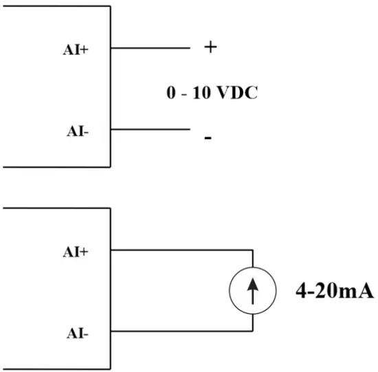
04 AI channels, no isolation (AI1 is a 4-20mA / 0-5 VDC / 0-10 VDC level input sensor )
ប្រើ DIP SW ដើម្បីកំណត់រចនាសម្ព័ន្ធការបញ្ចូលអាណាឡូក៖ 0-10V, 0-20mA
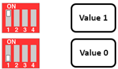
| តម្លៃ | ប្រភេទនៃ AI |
| 0 | 0-10 V |
| 1 | 0-20 mA |
ប្រភេទបញ្ចូល៖
- វាស់វ៉ុលtagអ៊ី: ៤.៨-១០ វី
- វាស់ចរន្ត: 0-20mA
- ការកំណត់រចនាសម្ព័ន្ធសម្រាប់ AI អានស្ថានភាពឡូជីខលដូចគ្នានឹង DI ប៉ុន្តែវាមិនត្រូវបានញែកដាច់ពីគ្នាជាមួយនឹងជួរជីពចរពី 0-24V
impedance បញ្ចូល៖
- វាស់វ៉ុលtage: 320 kΏ
- វាស់ចរន្ត: 499 Ώ
5.4.1 អានតម្លៃអាណាឡូក
ដំណោះស្រាយ ១៦ ប៊ីត
ភាពមិនលីនេអ៊ែរ៖ 0.1%
តម្លៃអាណាឡូកក្នុង Modbus Memory Map៖ 0-3900
ការចុះឈ្មោះតម្លៃអាណាឡូកក្នុង Modbus Memory Map៖
- តម្លៃអាណាឡូក AI1៖ រក្សាទុកតម្លៃអាណាឡូកនៃឆានែល 1
- តម្លៃអាណាឡូក AI2៖ រក្សាទុកតម្លៃអាណាឡូកនៃឆានែល 2
- តម្លៃអាណាឡូក AI3៖ រក្សាទុកតម្លៃអាណាឡូកនៃឆានែល 3
- តម្លៃអាណាឡូក AI4៖ រក្សាទុកតម្លៃអាណាឡូកនៃឆានែល 4
5.4.2 ការកំណត់រចនាសម្ព័ន្ធ AI ដំណើរការជា DI
គ្មានភាពឯកោទេ។
AI កំណត់រចនាសម្ព័ន្ធ AI ដើម្បីអានស្ថានភាពតក្កវិជ្ជាដូចគ្នានឹង DI ជាមួយជីពចរ ampពន្លឺពី 0-24V
មាន 2 counter threshold AIx: logic threshold 0 និង counter AIx: threshold logic 1 in the modbus table: 0-4095
- តម្លៃអាណាឡូកអាណាឡូកនៃ AI
- តម្លៃអាណាឡូកអាណាឡូកនៃ AI > counter AIx: threshold logic 1: ត្រូវបានចាត់ទុកថាជា Logic 1 state of AI
- Counter AIx៖ threshold logic 0 =
តម្លៃស្ថានភាពឡូជីខលនៃ AI នៅក្នុងតារាង Modbus Memory Map៖ 0-1
ការចុះឈ្មោះរក្សាទុកតម្លៃឡូជីខលនៅក្នុង Modbus Memory Map៖
- AI1___AI2៖ ស្ថានភាពឌីជីថល៖ រក្សាទុកស្ថានភាពឡូជីខលនៃឆានែល 1 និងឆានែល 2 ។
H_byte៖ AI1
L_byte៖ AI2 - AI3___AI4៖ ស្ថានភាពឌីជីថល៖ រក្សាទុកស្ថានភាពឡូជីខលនៃឆានែល 1 និងឆានែល 2 ។
H_byte៖ AI3
L_byte៖ AI4
5.4.3 Pulse Counter AI អតិបរមា 10Hz
តម្លៃរាប់ក្នុង Modbus Memory Map នៅពេលបន្ថែមលេខលើសពីកម្រិត វានឹងត្រឡប់ដោយស្វ័យប្រវត្តិ៖ 0 4294967295 (32 ប៊ីត)
ការចុះឈ្មោះដែលរក្សាទុកតម្លៃរាប់ក្នុង Modbus Memory Map មិនអាចលុបបានទេ៖
- Counter AI1: រក្សាទុកស្ថានភាពតក្កវិជ្ជានៃឆានែល 1
- ប្រឆាំង AI2: រក្សាទុកស្ថានភាពតក្កវិជ្ជានៃឆានែលទី 2
- ប្រឆាំង AI3: រក្សាទុកស្ថានភាពតក្កវិជ្ជានៃឆានែលទី 3
- ប្រឆាំង AI4: រក្សាទុកស្ថានភាពតក្កវិជ្ជានៃឆានែលទី 4
ការចុះឈ្មោះដែលរក្សាទុកតម្លៃរាប់ក្នុង Modbus Memory Map មិនអាចលុបបានទេ៖ - គ្មានការកំណត់ឡើងវិញ AI1: រក្សាទុកស្ថានភាពតក្កវិជ្ជានៃឆានែល 1
- គ្មានការកំណត់ឡើងវិញ AI2: រក្សាទុកស្ថានភាពតក្កវិជ្ជានៃឆានែល 2
- គ្មានការកំណត់ឡើងវិញ AI3: រក្សាទុកស្ថានភាពតក្កវិជ្ជានៃឆានែល 3
- គ្មានការកំណត់ឡើងវិញ AI4៖ រក្សាទុកស្ថានភាពតក្កវិជ្ជានៃឆានែលទី 4
៤ បញ្ជូនបន្ត
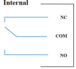
04 ឆានែលបញ្ជូនត SPDT NO / NC
ការវាយតម្លៃទំនាក់ទំនង: 2A / 24VDC, 0.5A / 220VAC
មាន LED ស្ថានភាព៖
- ដឹកនាំ៖ បិទទំនាក់ទំនង
- បិទ៖ បើកទំនាក់ទំនង
| ការចុះឈ្មោះបញ្ជូនបន្តលំនាំដើម | ស្ថានភាពនៃការបញ្ជូនតនៅពេលកំណត់ការផ្គត់ផ្គង់ថាមពលឡើងវិញ |
| 3 | ដំណើរការតាមការកំណត់រចនាសម្ព័ន្ធសំឡេងរោទិ៍ |
ការកំណត់រចនាសម្ព័ន្ធសំឡេងរោទិ៍៖
- HIHI: បញ្ជូនបន្ត 4 បើក
- HI: Relay 3 On
- LO: បញ្ជូនបន្ត 2 បើក
- LOLO៖ បញ្ជូនបន្ត 1 បើក
5.6 ទិន្នផលជីពចរ

01 ឆានែលអ្នកប្រមូលបើកចំហដាច់ដោយឡែក
Opto-coupler៖ ប្រភពបច្ចុប្បន្ន Imax = 10mA, Vceo = 80V
មុខងារ៖ បើក / បិទ, ម៉ាស៊ីនភ្លើងជីពចរ, PWM
5.6.1 មុខងារបើក/បិទ
កំណត់ការចុះឈ្មោះ Open-collector នៅក្នុងតារាង Modbus Memory Map៖
- កំណត់ Open-collector register: 1 => Pulse Output ON
- កំណត់ Open-collector register: 0 => Pulse Output OFF
5.6.2 ម៉ាស៊ីនភ្លើងជីពចរ
ទិន្នផលជីពចរបញ្ជូនអតិបរមា 65535 ជីពចរជាមួយនឹង Fmax 2.5kHz
កំណត់រចនាសម្ព័ន្ធការចុះឈ្មោះខាងក្រោមនៅក្នុងតារាង Modbus Memory Map៖
- កំណត់ការចុះឈ្មោះ “អ្នកប្រមូលបើកចំហ៖ លេខជីពចរ”៖ 0-65535 => លេខជីពចរ = 65535៖ ចាក់ផ្សាយ 65535 ជីពចរ
- កំណត់ការចុះឈ្មោះ “open collector: time cycle”: (0-65535) x0.1ms => Time Cycle = 4: Fmax 2.5kHz
- កំណត់ការចុះឈ្មោះ “open collector: time on”: (0-65535) x0.1ms => Time On: គឺជាពេលវេលាតក្កវិជ្ជា 1 នៃជីពចរ
- កំណត់ការចុះឈ្មោះ “open collector ctrl” = 3 => កំណត់រចនាសម្ព័ន្ធ Pulse Output ដើម្បីបង្កើតជីពចរ ហើយចាប់ផ្តើមជីពចរ បង្កើតចំនួនជីពចរគ្រប់គ្រាន់នៅក្នុង “open collector: pulse number” register => stop pulse generator ហើយចុះឈ្មោះ “open collector ctrl”= 0
PWM ១
ប្រេកង់អតិបរមា 2.5kHz
កំណត់រចនាសម្ព័ន្ធការចុះឈ្មោះខាងក្រោមនៅក្នុងតារាង Modbus Memory Map៖
- កំណត់ការចុះឈ្មោះ “open collector ctrl” = 2 => កំណត់រចនាសម្ព័ន្ធមុខងារ Pulse Output PWM
- កំណត់ការចុះឈ្មោះ “open collector: time cycle”: (0-65535) x0.1ms => Time Cycle = 4: Fmax 2.5kHz
- កំណត់ការចុះឈ្មោះ “open collector: time on”: (0-65535) x0.1ms => Time On: គឺជាពេលវេលាតក្កវិជ្ជា 1 នៃជីពចរ
ការដំឡើង
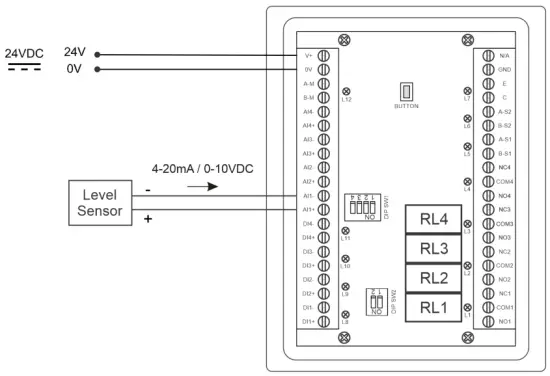
6.1 វិធីសាស្រ្តដំឡើង
 6.2 ខ្សែជាមួយឧបករណ៍ចាប់សញ្ញាកម្រិត

ការកំណត់រចនាសម្ព័ន្ធ
7.1 អេក្រង់ដើម

ស្គ្រីន៖ ប្តូរទៅអេក្រង់ទី 2 ដែលមានព័ត៌មានលំអិតបន្ថែម
ការដាស់តឿន: បង្ហាញការជូនដំណឹងកម្រិត
គេហទំព័រ៖ ត្រឡប់ទៅអេក្រង់ដើមវិញ។
កំណត់រចនាសម្ព័ន្ធ។ (ពាក្យសម្ងាត់លំនាំដើម៖ ក)៖ ចូលទៅកាន់អេក្រង់ការកំណត់
7.2 ការកំណត់អេក្រង់ (ពាក្យសម្ងាត់លំនាំដើម៖ ក)
7.2.1 អេក្រង់ 1
![daviteq LFC128 2 Advanced Level Display Controller - Home Screen 1] '](https://manuals.plus/wp-content/uploads/2025/08/daviteq-LFC128-2-Advanced-Level-Display-Controller-Home-Screen-1-550x305.png)
ADC៖ តម្លៃសញ្ញាឆៅនៃឆានែល AI1
កម្រិត (ឯកតា): កម្រិតត្រូវគ្នាទៅនឹងសញ្ញា ADC បន្ទាប់ពីការកំណត់រចនាសម្ព័ន្ធ
កម្រិតខ្ទង់ទសភាគ៖ ចំនួនខ្ទង់ទសភាគបន្ទាប់ពីចំនុចនៃកម្រិត 0-3 (00000, 1111.1, 222.22, 33.333)
កម្រិតឯកតា: ឯកតាកម្រិត 0-3 (0: mm, 1: cm, 2: m, 3: inch)
ក្នុង ១៖ បញ្ចូលតម្លៃ ADC បន្ទាប់ពីដាក់ 4 mA/0 VDC ទៅក្នុង AI1 សម្រាប់ការក្រិតនៅកម្រិត 0
មាត្រដ្ឋាន 1៖ តម្លៃកម្រិតដែលបានបង្ហាញត្រូវនឹងតម្លៃដែលបានបញ្ចូលក្នុង 1 (ជាធម្មតា 0)
ក្នុង ១៖ បញ្ចូលតម្លៃ ADC បន្ទាប់ពីដាក់ 20 mA/10 VDC ទៅក្នុង AI1 សម្រាប់ការក្រិតតាមកម្រិតពេញ
មាត្រដ្ឋាន 2៖ តម្លៃកម្រិតដែលបង្ហាញត្រូវគ្នាទៅនឹងតម្លៃដែលបានបញ្ចូលក្នុង 2
កម្រិតវិសាលភាព៖ តម្លៃអតិបរមានៃកម្រិត (កម្រិតកម្រិត ≥ មាត្រដ្ឋាន 2)
បរិមាណខ្ទង់ទសភាគ៖ ចំនួនខ្ទង់ទសភាគបន្ទាប់ពីចំនុចនៃភាគ 0-3 (00000, 1111.1, 222.22, 33.333)
បរិមាណឯកតា៖ ឯកតានៃបរិមាណ 0-3 (0: ភ្លឺ, 1: សង់ទីម៉ែត្រ, 2: m3, 3:%)
7.2.2 អេក្រង់ 2

កម្រិត Hi Hi កំណត់ចំណុច (ឯកតា): កម្រិតខ្ពស់នៃកម្រិតសំឡេងរោទិ៍
កម្រិត Hi Hi Hys (ឯកតា): hysteresis កម្រិតខ្ពស់នៃកម្រិតសំឡេងរោទិ៍
កម្រិត Hi កំណត់ចំណុច (ឯកតា): កម្រិតខ្ពស់នៃកម្រិតសំឡេងរោទិ៍
កម្រិត Hi Hys (ឯកតា): hysteresis កម្រិតខ្ពស់នៃកម្រិតសំឡេងរោទិ៍
កម្រិត Lo ចំណុចកំណត់ (ឯកតា)៖ កម្រិតសំឡេងរោទិ៍ទាប
កម្រិត Lo Hys (ឯកតា): hysteresis កម្រិតទាបនៃកម្រិតសំឡេងរោទិ៍
កម្រិត Lo Lo កំណត់ចំណុច (ឯកតា): កម្រិតទាបនៃកម្រិតសំឡេងរោទិ៍
កម្រិត Lo Lo Hys (ឯកតា): កម្រិតទាប hysteresis កម្រិតសំឡេងរោទិ៍
របៀបជូនដំណឹង៖ 0: កម្រិត, 1: កម្រិតសំឡេង
កម្រិតសំឡេង (ឯកតា)៖ តម្លៃអតិបរមានៃកម្រិតសំឡេង
7.2.3 អេក្រង់ 3

កម្រិតសំឡេង Hi Hi កំណត់ចំណុច (ឯកតា): កម្រិតសំឡេងរោទិ៍កម្រិតខ្ពស់
កម្រិតសំឡេង Hi Hi Hys (ឯកតា): កម្រិតសំឡេងខ្ពស់ hysteresis នៃកម្រិតសំឡេងរោទិ៍
កម្រិតសំឡេង Hi កំណត់ចំណុច (ឯកតា): កម្រិតសំឡេងរោទិ៍ខ្ពស់។
កម្រិតសំឡេង Hi Hys (ឯកតា)៖ កម្រិតសំឡេងខ្ពស់នៃសំឡេងរោទិ៍
កម្រិតសំឡេង Lo កំណត់ចំណុច (ឯកតា): កម្រិតសំឡេងរោទិ៍ទាប
បរិមាណ Lo Hys (ឯកតា): កម្រិតសំឡេងទាប hysteresis នៃកម្រិតសំឡេងរោទិ៍
កម្រិតសំឡេង Lo Lo កំណត់ចំណុច (ឯកតា): កម្រិតសំឡេងរោទិ៍ទាបទាប
បរិមាណ Lo Lo Hys (ឯកតា): កម្រិតសំឡេងទាប hysteresis នៃកម្រិតសំឡេងរោទិ៍
ដំណើរការសរុប៖ ដំណើរការមុខងារសរុប។ 0-1 (0: ទេ 1: បាទ)
7.2.4 អេក្រង់ 4

ការបំពេញ (ឯកតា): មុខងារសរុប៖ សរុបដាក់ក្នុងធុង
ការប្រើប្រាស់ (ឯកតា)៖ មុខងារសរុប៖ ការប្រើប្រាស់សរុបនៃធុង
ខ្ទង់ទសភាគសរុប៖ ចំនួនទសភាគនៃប៉ារ៉ាម៉ែត្រ ការបំពេញ ការប្រើប្រាស់ ការបំពេញ NRT ការប្រើប្រាស់ NRT នៅលើទំព័របង្ហាញ (មិនមែនទំព័រកំណត់)
Delta Total (ឯកតា)៖ កម្រិត Hysteresis នៃមុខងារសរុប
អាសយដ្ឋាន Modbus៖ អាសយដ្ឋាន Modbus នៃ LFC128-2, 1-247
Modbus Baurate S1៖ 0-1 (0 : 9600 , 1 : 19200)
Modbus Parity S1៖ 0-2 (0: គ្មាន, 1: សេស, 2: គូ)
Modbus Baurate S2៖ 0-1 (0 : 9600 , 1 : 19200)
Modbus Parity S2៖ 0-2 (0: គ្មាន, 1: សេស, 2: គូ)
ចំនួនពិន្ទុ៖ ចំនួនពិន្ទុក្នុងតារាងដើម្បីបំប្លែងពីកម្រិតមួយទៅកម្រិតសំឡេង 1-166
7.2.5 អេក្រង់ 5

ចំណុច 1 កម្រិត (ឯកតាកម្រិត): កម្រិតនៅចំណុច 1
ចំណុចទី 1 កម្រិតសំឡេង (ឯកតាកម្រិតសំឡេង): បរិមាណដែលត្រូវគ្នានៅចំណុច 1
ចំណុច ១៦៦ កម្រិត (ឯកតាកម្រិត)៖ កម្រិតប្រេងឥន្ធនៈនៅចំណុច ១៦៦
ចំណុចទី 166 កម្រិតសំឡេង (ឯកតាកម្រិតសំឡេង): បរិមាណដែលត្រូវគ្នានៅចំណុច 166
7.2.6 អេក្រង់ 6

ពាក្យសម្ងាត់៖ ពាក្យសម្ងាត់ដើម្បីបញ្ចូលទំព័រការកំណត់ 8 តួអក្សរ ASCII
ឈ្មោះធុង៖ ឈ្មោះធុងត្រូវបានបង្ហាញនៅលើអេក្រង់មេ
ការដោះស្រាយបញ្ហា
| ទេ | បាតុភូត | ហេតុផល | ដំណោះស្រាយ |
| 1 | Modbus បរាជ័យក្នុងការទំនាក់ទំនង | ស្ថានភាព Modbus LED៖ LED បិទ៖ មិនបានទទួលទិន្នន័យ LED កំពុងភ្លឹបភ្លែតៗ៖ ការកំណត់រចនាសម្ព័ន្ធ Modbus មិនត្រឹមត្រូវទេ | ពិនិត្យការតភ្ជាប់ ពិនិត្យមើលការកំណត់រចនាសម្ព័ន្ធ Modbus៖ អាស័យដ្ឋាន អត្រា Baud ភាពស្មើគ្នា |
| 2 | អស់ពេល Modbus | សំលេងរំខានលេចឡើងនៅលើបន្ទាត់ | កំណត់រចនាសម្ព័ន្ធ Baudrate 9600 ហើយប្រើខ្សែគូរមួលដែលមានការការពារប្រឆាំងនឹងការកកស្ទះ |
| 3 | ឧបករណ៍ចាប់សញ្ញាត្រូវបានផ្តាច់ | ឧបករណ៍ចាប់សញ្ញា និង LFC128 បានបាត់បង់ការតភ្ជាប់ | ពិនិត្យការភ្ជាប់ ពិនិត្យប្រភេទឧបករណ៍ចាប់សញ្ញា (LFC128-2 តភ្ជាប់តែ 0-10VDC / 4- 20mA ប្រភេទឧបករណ៍ចាប់សញ្ញាអាណាឡូក) ពិនិត្យកុងតាក់ដើម្បីមើលថាតើវាត្រូវបានបើកត្រឹមត្រូវ ពិនិត្យមើលថាឧបករណ៍ភ្ជាប់ឧបករណ៍ចាប់សញ្ញាត្រឹមត្រូវ AI1 |
| 4 | កំហុសតារាងលីនេអ៊ែរ | កំហុសនៃតារាងបំប្លែងពីកម្រិតទៅកម្រិតសំឡេង | ពិនិត្យការកំណត់រចនាសម្ព័ន្ធតារាងបំប្លែងពីកម្រិតមួយទៅកម្រិតសំឡេង |
ទំនាក់ទំនងគាំទ្រ
ក្រុមហ៊ុនផលិត
Daviteq Technologies Inc
No.11 Street 2G, Nam Hung Vuong Res., An Lac Ward, Binh Tan Dist., Ho Chi Minh City, Vietnam.
Tel: +84-28-6268.2523/4 (ext.122)
អ៊ីមែល៖ info@daviteq.com
www.daviteq.com
ឯកសារ/ធនធាន
 |
daviteq LFC128-2 ឧបករណ៍បញ្ជាការបង្ហាញកម្រិតកម្រិតខ្ពស់ [pdf] សៀវភៅណែនាំ LFC128-2, LFC128-2 Advanced Level Display Controller, Advanced Level Display Controller, Level Display Controller, Display Controller |