![]() Itọkasi Ipele
Itọkasi Ipele
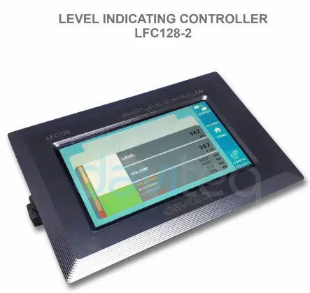
Adarí LFC128-2
Itọnisọna olumulo fun ipele ti o nfihan adari LFC128-2
LFC128-2-MN-EN-01 JUN-2020
LFC128-2 To ti ni ilọsiwaju Ipele Ifihan Adarí
Iwe yi wa ni loo fun awọn wọnyi awọn ọja
| SKU | LFC128-2 | HW Ver. | 1.0 | FW Ver. | 1.1 |
| Koodu Nkan | LFC128-2 | Alakoso Itọkasi Ipele, 4AI/DI, 4DI, 4xRelay, 1xPulse Output, 2 x RS485/ModbusRTU-Ibaraẹnisọrọ Ẹrú | |||
Awọn iṣẹ Iyipada Wọle
| HW Ver. | FW Ver. | Ojo ifisile | Awọn iṣẹ Yipada |
| 1.0 | 1.1 | Oṣu Kẹjọ-2020 | |
Ọrọ Iṣaaju
LFC128-2 jẹ oludari ifihan ipele to ti ni ilọsiwaju. Ọja naa ṣepọ Modbus RTU ni wiwo lati ṣe iranlọwọ PLC / SCADA / BMS ati eyikeyi ibudo IoT le sopọ lati ṣe atẹle. LFC128-2 ni apẹrẹ ti o rọrun sibẹsibẹ ti o lagbara pẹlu 4 AI / DI, 4 DI, 4 Relays, 1 Pulse pulse output, 2 RS485 Slave ModbusRTU gbigba wọn laaye lati sopọ pẹlu awọn ẹrọ lọpọlọpọ. Pẹlu imọ-ẹrọ to ti ni ilọsiwaju ti o pese iduroṣinṣin to gaju ati igbẹkẹle, ọpọlọpọ awọn iṣẹ, fifi sori ẹrọ ti o rọrun pẹlu iboju ifọwọkan ati wiwo ọrẹ ṣe iranlọwọ ni wiwo ipele ipele.
Sipesifikesonu
| Awọn igbewọle oni-nọmba | 04 x Ports, opto-coupler, 4.7 kohms input resisrtance, 5000V rms ipinya, Logic 0 (0-1VDC), Logic 1 (5-24VDC), Awọn iṣẹ: kannaa ipo 0/1 tabi Pulse kika (32 bit counter pẹlu max 4kHz pulse) |
| Awọn igbewọle Analog | 04 x Ports, yan laarin 0-10VDC input tabi 0-20mA input, 12 bit Resolution, le ti wa ni tunto bi Digital input nipa DIP yipada (max 10VDC input) AI1 ibudo ni a 0-10 VDC / 4-20 mA ipele sensọ ibudo ibudo. |
| Iṣajade yii | 04 x Awọn ebute oko oju omi, Relays elekitiro-mechanical, SPDT, Rating olubasọrọ 24VDC/2A tabi 250VAC/5A, Awọn afihan LED |
| O wu Polusi | 01 x Awọn ebute oko oju omi, olugba-iṣiro, ipinya opto, max 10mA ati 80VDC, Titan/pa Iṣakoso, Pulser (max 2.5Khz, max 65535 Pulses) tabi PWM (max 2.5Khz) |
| Ibaraẹnisọrọ | 02 x ModbusRTU-ẹrú, RS485, iyara 9600 tabi 19200, LED Atọka |
| Bọtini atunto | Fun tunto 02 x RS485 Ẹrú ibudo si eto aiyipada (9600, Ko si igbẹ, 8 bit) |
| Iboju iru | Afi ika te |
| Ibi ti ina elekitiriki ti nwa | 9..36VDC |
| Lilo agbara | 200mA @ 24VDC ipese |
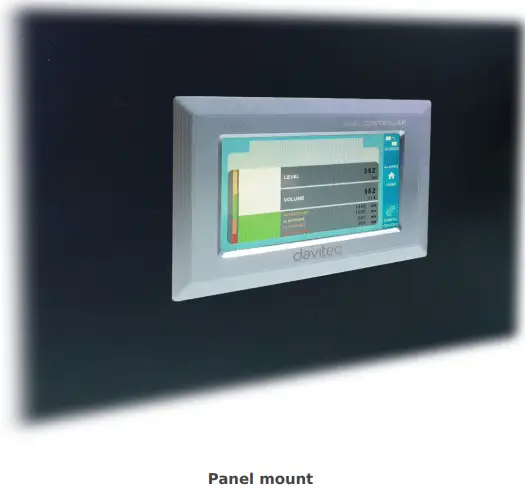
| Iṣagbesori iru | Panel òke |
| Ohun amorindun Terminal | ipolowo 5.0mm, Rating 300VAC, waya iwọn 12-24AWG |
| Ṣiṣẹ otutu / ọriniinitutu | 0..60 degC / 95% RH ti kii-condensing |
| Iwọn | H93xW138xD45 |
| Apapọ iwuwo | 390 giramu |
ọja Awọn aworan


Ilana Isẹ

5.1 Modbus ibaraẹnisọrọ

02 x RS485 / ModbusRTU-ẹrú
Ilana: Modbus RTU
Adirẹsi: 1 - 247, 0 ni adirẹsi Broadcast
Oṣuwọn Baud: 9600, 19200
Iṣọkan: ko si, odd, ani
- Atọka ipo LED:
- Mu lori: modbus ibaraẹnisọrọ O dara
- Led si pawalara: data ti o gba ṣugbọn ibaraẹnisọrọ modbus ko tọ, nitori iṣeto Modbus ti ko tọ: adirẹsi, baudrate
- Ti mu kuro: LFC128-2 ko gba data, ṣayẹwo asopọ naa
Awọn iforukọsilẹ Memmap
KA nlo aṣẹ 03, WRITE nlo aṣẹ 16
Iṣeto aiyipada:
- Adirẹsi: 1
- Baudrate ẹrú 1: 9600
- Parity ẹrú 1: kò
- Baudrate ẹrú 2: 9600
- Parity ẹrú 2: kò
| Modbus Forukọsilẹ | Hex adr | # ti awọn iforukọsilẹ |
Apejuwe | Ibiti o | Aiyipada | Ọna kika | Ohun ini | Ọrọìwòye |
| 0 | 0 | 2 | ẹrọ alaye | LFC1 | okun | Ka | ||
| 8 | 8 | 1 | DI1 DI2: oni ipo | 0-1 | oju8 | Ka | H_byte: DI1 L_baiti: DI2 | |
| 9 | 9 | 1 | DI3 DI4: oni ipo | 0-1 | oju8 | Ka | H_byte: DI3 L_baiti: DI4 | |
| 10 | A | 1 | AI1 AI2: oni ipo | 0-1 | oju8 | Ka | H_byte: AI1 L_byte: AI2 | |
| 11 | B | 1 | AI3 AI4: oni ipo | 0-1 | oju8 | Ka | H_byte: AI3 L_byte: AI4 | |
| 12 | C | 1 | AI1: afọwọṣe iye | oju16 | Ka | |||
| 13 | D | 1 | AI2: afọwọṣe iye | oju16 | Ka | |||
| 14 | E | 1 | AI3: afọwọṣe iye | oju16 | Ka | |||
| 15 | F | 1 | AI4: afọwọṣe iye | oju16 | Ka | |||
| 16 | 10 | 2 | AI1: iye iwọn | leefofo loju omi | Ka | |||
| 18 | 12 | 2 | AI2: iye iwọn | leefofo loju omi | Ka | |||
| 20 | 14 | 2 | AI3: iye iwọn | leefofo loju omi | Ka | |||
| 22 | 16 | 2 | AI4: iye iwọn | leefofo loju omi | Ka | |||
| 24 | 18 | 1 | yii 1 | 0-1 | oju16 | Ka | ||
| 25 | 19 | 1 | yii 2 | 0-1 | oju16 | Ka | ||
| 26 | 1A | 1 | yii 3 | 0-1 | oju16 | Ka | ||
| 27 | 1B | 1 | yii 4 | 0-1 | oju16 | Ka | ||
| 28 | 1C | 1 | ìmọ-odè ctrl | 0-3 | oju16 | Ka/Kọ | 0: pa 1: lori 2: pwm, pulse nigbagbogbo 3: pulse, nigbati nọmba pulse to, ctrl = 0 | |
| 30 | 1E | 2 | counter DI1 | oju32 | Ka/Kọ | counter writable, erasable | ||
| 32 | 20 | 2 | counter DI2 | oju32 | Ka/Kọ | counter writable, erasable | ||
| 34 | 22 | 2 | counter DI3 | oju32 | Ka/Kọ | counter writable, erasable | ||
| 36 | 24 | 2 | counter DI4 | oju32 | Ka/Kọ | counter writable, erasable | ||
| 38 | 26 | 2 | counter AI1 | oju32 | Ka/Kọ | counter writable, erasable, max igbohunsafẹfẹ 10Hz | ||
| 40 | 28 | 2 | counter AI2 | oju32 | Ka/Kọ | counter writable, erasable, max igbohunsafẹfẹ 10Hz | ||
| 42 | 2A | 2 | counter AI3 | oju32 | Ka/Kọ | counter writable, erasable, max igbohunsafẹfẹ 10Hz | ||
| 44 | 2C | 2 | counter AI4 | oju32 | Ka/Kọ | counter writable, erasable, max igbohunsafẹfẹ 10Hz | ||
| 46 | 2E | 2 | DI1: akoko lori | oju32 | Ka/Kọ | iṣẹju-aaya | ||
| 48 | 30 | 2 | DI2: akoko lori | oju32 | Ka/Kọ | iṣẹju-aaya | ||
| 50 | 32 | 2 | DI3: akoko lori | oju32 | Ka/Kọ | iṣẹju-aaya | ||
| 52 | 34 | 2 | DI4: akoko lori | oju32 | Ka/Kọ | iṣẹju-aaya | ||
| 54 | 36 | 2 | AI1: akoko lori | oju32 | Ka/Kọ | iṣẹju-aaya | ||
| 56 | 38 | 2 | AI2: akoko lori | oju32 | Ka/Kọ | iṣẹju-aaya | ||
| 58 | 3A | 2 | AI3: akoko lori | oju32 | Ka/Kọ | iṣẹju-aaya | ||
| 60 | 3C | 2 | AI4: akoko lori | oju32 | Ka/Kọ | iṣẹju-aaya | ||
| 62 | 3E | 2 | DI1: akoko isinmi | oju32 | Ka/Kọ | iṣẹju-aaya | ||
| 64 | 40 | 2 | DI2: akoko isinmi | oju32 | Ka/Kọ | iṣẹju-aaya | ||
| 66 | 42 | 2 | DI3: akoko isinmi | oju32 | Ka/Kọ | iṣẹju-aaya | ||
| 68 | 44 | 2 | DI4: akoko isinmi | oju32 | Ka/Kọ | iṣẹju-aaya | ||
| 70 | 46 | 2 | AI1: akoko isinmi | oju32 | Ka/Kọ | iṣẹju-aaya | ||
| 72 | 48 | 2 | AI2: akoko isinmi | oju32 | Ka/Kọ | iṣẹju-aaya | ||
| 74 | 4A | 2 | AI3: akoko isinmi | oju32 | Ka/Kọ | iṣẹju-aaya | ||
| 76 | 4C | 2 | AI4: akoko isinmi | oju32 | Ka/Kọ | iṣẹju-aaya | ||
| 128 | 80 | 2 | counter DI1 | oju32 | Ka | counter ko le kọ, nu | ||
| 130 | 82 | 2 | counter DI2 | oju32 | Ka | counter ko le kọ, nu | ||
| 132 | 84 | 2 | counter DI3 | oju32 | Ka | counter ko le kọ, nu | ||
| 134 | 86 | 2 | counter DI4 | oju32 | Ka | counter ko le kọ, nu | ||
| 136 | 88 | 2 | counter AI1 | oju32 | Ka | counter ko le kọ, nu; max igbohunsafẹfẹ 10Hz | ||
| 138 | 8A | 2 | counter AI2 | oju32 | Ka | counter ko le kọ, nu; max igbohunsafẹfẹ 10Hz | ||
| 140 | 8C | 2 | counter AI3 | oju32 | Ka | counter ko le kọ, nu; max igbohunsafẹfẹ 10Hz | ||
| 142 | 8E | 2 | counter AI4 | oju32 | Ka | counter ko le kọ, nu; max igbohunsafẹfẹ 10Hz | ||
| 256 | 100 | 1 | modbus adirẹsi ẹrú | 1-247 | 1 | oju16 | Ka/Kọ |
|
| 257 | 101 | 1 | modbus baudrate ẹrú 1 | 0-1 | 0 | oju16 | Ka/Kọ |
0: 9600, 1: 19200 |
| 258 | 102 | 1 | modbus parity ẹrú 1 | 0-2 | 0 | oju16 | Ka/Kọ |
0: ko si, 1: odd, 2: ani |
5.2 Tun Bọtini
Nigbati o ba di bọtini atunto fun awọn aaya 4, LFC 128-2 yoo tun atunto aiyipada pada si 02 x RS485 / Modbus
RTU-ẹrú.
Iṣeto Modbus RTU aiyipada:
- Adirẹsi: 1
- Oṣuwọn Baud: 9600
- Parity: ko si
5.3 Digital Input

Ni pato:
- 04 awọn ikanni DI, sọtọ
- Atako igbewọle: 4.7 kΏ
- Iyasoto Voltage: 5000Vrms
- Ipele kannaa 0: 0-1V
- Ipele kannaa 1: 5-24V
- Iṣẹ:
- Ka kannaa 0/1
- Pulse Counter
5.3.1 Ka awọn mogbonwa ipinle 0/1
Logic iye ni Modbus Memory Map: 0-1
Forukọsilẹ lati tọju awọn iye oye inu Modbus Map Iranti:
- DI1__DI2: ipo oni nọmba: tọju ipo ọgbọn ti ikanni 1 ati ikanni 2.
H_byte: DI1
L_baiti: DI2 - DI3__DI4: ipo oni nọmba: tọju ipo ọgbọn ti ikanni 3 ati ikanni 4.
H_byte: DI3
L_baiti: DI4
5.3.2 Polusi Counter
Iye Counter ni Modbus Memory Map, nigba fifi nọmba kun ju iloro, yoo pada laifọwọyi: 0 4294967295 (32bits)
Iforukọsilẹ ti o tọju iye Counter ni Maapu Iranti Modbus ko le parẹ:
- Counter DI1: tọju ipo ọgbọn ti ikanni 1
- Counter DI2: tọju ipo ọgbọn ti ikanni 2
- Counter DI3: tọju ipo ọgbọn ti ikanni 3
- Counter DI4: tọju ipo ọgbọn ti ikanni 4
Iforukọsilẹ ti o tọju iye Counter ni Maapu Iranti Modbus ko le parẹ: - Ko si counter atunto DI1: tọju ipo ọgbọn ti ikanni 1
- Ko si counter atunto DI2: tọju ipo ọgbọn ti ikanni 2
- Ko si counter atunto DI3: tọju ipo ọgbọn ti ikanni 3
- Ko si counter atunto DI4: tọju ipo ọgbọn ti ikanni 4
Ipo counter Pulse:
Iwọn-iyara-kekere ka kere ju 10Hz pẹlu àlẹmọ, egboogi-jamming:
- Ṣeto iforukọsilẹ “counter DI1: akoko àlẹmọ” = 500-2000: Ikanni 1 ka awọn iṣọn ti o kere ju 10Hz
- Ṣeto iforukọsilẹ “counter DI2: akoko àlẹmọ” = 500-2000: Ikanni 2 ka awọn iṣọn ti o kere ju 10Hz
- Ṣeto iforukọsilẹ “counter DI3: akoko àlẹmọ” = 500-2000: Ikanni 3 ka awọn iṣọn ti o kere ju 10Hz
- Ṣeto iforukọsilẹ “counter DI4: akoko àlẹmọ” = 500-2000: Ikanni 4 ka awọn iṣọn ti o kere ju 10Hz
- Iwọn pulse iyara to gaju pẹlu igbohunsafẹfẹ 2KHz ti o pọju laisi àlẹmọ:
- Ṣeto iforukọsilẹ “counter DI1: akoko àlẹmọ” = 1: ikanni 1 ka awọn iṣan pẹlu Fmax = 2kHz
- Ṣeto iforukọsilẹ “counter DI2: akoko àlẹmọ” = 1: ikanni 2 ka awọn iṣan pẹlu Fmax = 2kHz
- Ṣeto iforukọsilẹ “counter DI3: akoko àlẹmọ” = 1: ikanni 3 ka awọn iṣan pẹlu Fmax = 2kHz
- Ṣeto iforukọsilẹ “counter DI4: akoko àlẹmọ” = 1: ikanni 4 ka awọn iṣan pẹlu Fmax = 2kHz
5.4 Afọwọṣe Input
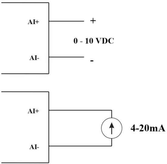
Awọn ikanni 04 AI, ko si ipinya (AI1 jẹ 4-20mA / 0-5 VDC / 0-10 VDC titẹ sensọ ipele)
Lo DIP SW lati tunto titẹ sii Analog: 0-10V, 0-20mA
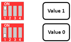
| Iye | Iru AI |
| 0 | 0-10 V |
| 1 | 0-20 mA |
Iru igbewọle:
- Iwọn iwọntage: 0-10V
- Iwọn lọwọlọwọ: 0-20mA
- Iṣeto ni fun AI ka ipo ọgbọn kanna bi DI, ṣugbọn ko ya sọtọ pẹlu iwọn pulse kan ti 0-24V
Imuwọle igbewọle:
- Iwọn iwọntage: 320 k
- Ṣe iwọn lọwọlọwọ: 499 Ώ
5.4.1 Ka iye Analog
O ga 12 die -die
Ti kii ṣe ila-ila: 0.1%
Afọwọṣe iye ni Modbus Memory Map: 0-3900
Iforukọsilẹ iye Analog ni Maapu Iranti Modbus:
- Iye afọwọṣe AI1: tọju iye Analog ti ikanni 1
- Iye afọwọṣe AI2: tọju iye Analog ti ikanni 2
- Iye afọwọṣe AI3: tọju iye Analog ti ikanni 3
- Iye afọwọṣe AI4: tọju iye Analog ti ikanni 4
5.4.2 AI iṣeto ni ṣiṣẹ bi DI
Ko si ipinya
AI Tunto AI lati ka ipo kannaa kanna bi DI pẹlu pulse amplitude lati 0-24V
2 counter threshold AIx: iloro oye 0 ati counter AIx: ero inu ala 1 ninu tabili modbus: 0-4095
- Analog Analog iye ti AI
- Iwọn Analog Analog ti AI> counter AIx: oye iloro 1: ni a gba pe o jẹ Logic 1 state of AI
- Counter AIx: ala kannaa 0 =
Logic Logical ipo iye ti AI ni Modbus Memory Map tabili: 0-1
Iforukọsilẹ naa tọju awọn iye oye ni Modbus Map Iranti:
- AI1____AI2: Ipo oni-nọmba: tọju ipo ọgbọn ti ikanni 1 ati ikanni 2.
H_byte: AI1
L_baiti: AI2 - AI3____AI4: Ipo oni-nọmba: tọju ipo ọgbọn ti ikanni 1 ati ikanni 2.
H_byte: AI3
L_baiti: AI4
5.4.3 Pulse Counter AI max 10Hz
Iye counter ni Modbus Memory Map, nigba fifi nọmba kun ni ikọja ala, yoo pada laifọwọyi: 0 4294967295 (32bits)
Iforukọsilẹ ti o tọju iye Counter ni Maapu Iranti Modbus ko le parẹ:
- Counter AI1: tọju ipo ọgbọn ti ikanni 1
- Counter AI2: fi ipo oye ti ikanni 2 pamọ
- Counter AI3: fi ipo oye ti ikanni 3 pamọ
- Counter AI4: fi ipo oye ti ikanni 4 pamọ
Iforukọsilẹ ti o tọju iye Counter ni Maapu Iranti Modbus ko le parẹ: - Ko si counter atunto AI1: tọju ipo ọgbọn ti ikanni 1
- Ko si counter atunto AI2: tọju ipo ọgbọn ti ikanni 2
- Ko si counter atunto AI3: tọju ipo ọgbọn ti ikanni 3
- Ko si counter atunto AI4: fi ipo oye ti ikanni 4 pamọ
5.5 Ifiranṣẹ
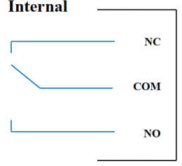
04 ikanni Relay SPDT KO / NC
Iwọn olubasọrọ: 2A / 24VDC, 0.5A / 220VAC
Awọn LED ipo wa:
- Ti mu siwaju: Olubasọrọ sunmọ
- Ti mu kuro: Ṣii olubasọrọ
| Iforukọsilẹ Yii aiyipada | Ipo ti relays nigba ti ntun awọn ipese agbara |
| 3 | Ṣiṣẹ ni ibamu si iṣeto Itaniji |
Iṣeto ni Itaniji:
- HIHI : Relay 4 Lori
- HI : Relay 3 Lori
- LO : Relay 2 Lori
- LOLO: Relay 1 On
5.6 Pulse wu

01 sọtọ ìmọ-odè ikanni
Opto-koupler: Orisun lọwọlọwọ Imax = 10mA, Vceo = 80V
Awọn iṣẹ: Tan-an / Paa, olupilẹṣẹ pulse, PWM
5.6.1 Tan / Pa iṣẹ
Ṣeto iforukọsilẹ Ṣii-odè ni tabili Map Iranti Modbus:
- Ṣeto iforukọsilẹ Ṣii-odè: 1 => Ijade Pulse ON
- Ṣeto iforukọsilẹ Ṣii-odè: 0 => PA Ijadejade Pulse
5.6.2 Pulse monomono
Imujade Pulse n gbejade iwọn 65535 ti o pọju, pẹlu Fmax 2.5kHz
Tunto awọn iforukọsilẹ atẹle ni tabili Map Iranti Modbus:
- Ṣeto iforukọsilẹ “olukojọ ṣiṣi: nọmba pulse”: 0-65535 => Nọmba Pulse = 65535: igbohunsafefe 65535 pulses
- Ṣeto iforukọsilẹ “olukojọ ṣiṣi: iyipo akoko”: (0-65535) x0.1ms => Ilana Aago = 4: Fmax 2.5kHz
- Ṣeto iforukọsilẹ “olukojọ ṣiṣi: akoko wa”: (0-65535) x0.1ms => Aago Lori: ni akoko oye 1 ti pulse
- Ṣeto iforukọsilẹ “open Collector ctrl” = 3 => tunto Ijade Pulse lati ṣe ipilẹṣẹ pulse ki o bẹrẹ si pulse, ṣe agbejade nọmba ti o to ninu iforukọsilẹ “odè ṣiṣi: nọmba pulse” forukọsilẹ => da olupilẹṣẹ pulse duro ki o forukọsilẹ ”odè-odè ctrl ”= 0
5.6.3 PWM
Igbohunsafẹfẹ ti o pọju 2.5kHz
Tunto awọn iforukọsilẹ atẹle ni tabili Map Iranti Modbus:
- Ṣeto iforukọsilẹ “odè-odè ctrl” = 2 => tunto Iṣẹjade Pulse PWM
- Ṣeto iforukọsilẹ “olukojọ ṣiṣi: iyipo akoko”: (0-65535) x0.1ms => Ilana Aago = 4: Fmax 2.5kHz
- Ṣeto iforukọsilẹ “olukojọ ṣiṣi: akoko wa”: (0-65535) x0.1ms => Aago Lori: ni akoko oye 1 ti pulse
Fifi sori ẹrọ
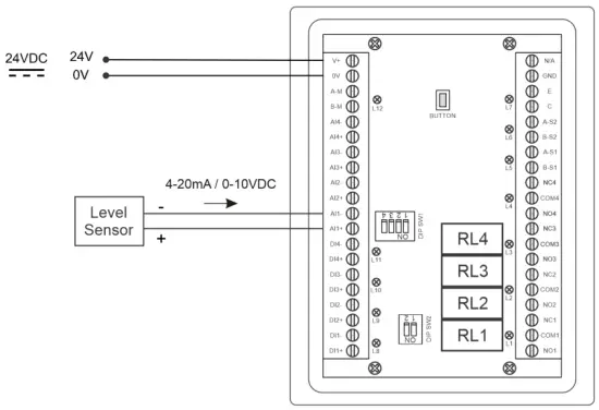
6.1 fifi sori ọna
 6.2 Wiwa pẹlu sensọ Ipele

Iṣeto ni
7.1 Iboju Ile

ẸRỌ: Yipada si iboju 2nd pẹlu alaye alaye diẹ sii
Awọn itọju: Ṣe afihan Itaniji Ipele
ILE: Pada si Iboju ile
CONFIG. (Ọrọigbaniwọle aiyipada: a): Lọ si Iboju Eto
7.2 Eto iboju (Ọrọigbaniwọle aiyipada: a)
7.2.1 Iboju 1
![daviteq LFC128 2 Alakoso Ifihan Ipele Ilọsiwaju - Iboju ile 1] '](https://manuals.plus/wp-content/uploads/2025/08/daviteq-LFC128-2-Advanced-Level-Display-Controller-Home-Screen-1-550x305.png)
ADCs: Aise iye ifihan agbara ti ikanni AI1
Ipele (Ẹyọ): Ipele naa ni ibamu si ifihan agbara ADC lẹhin iṣeto
Ipele eleemewa PlacesNọmba eleemewa ti awọn nọmba lẹhin aami Ipele 0-3 (00000, 1111.1, 222.22, 33.333)
Ipele ẹyọkan: awọn ipele ipele, 0-3 (0: mm, 1: cm, 2: m, 3: inch)
Ninu 1: Tẹ iye ADC sii lẹhin fifi 4 mA / 0 VDC sinu AI1 fun isọdiwọn ni ipele 0
Iwọn 1: Iwọn ipele ti o han ni ibamu si iye ti a tẹ sinu 1 (nigbagbogbo 0)
Ninu 2: Tẹ iye ADC sii lẹhin fifi 20 mA / 10 VDC sinu AI1 fun isọdọtun ni ipele kikun
Iwọn 2: Iye ipele ti o han ni ibamu si iye ti a tẹ sinu Ni 2
Ipele Ipele: Iye ti o pọju ti Ipele (Ipele Igba ≥ Iwọn 2)
Iwọn Awọn aaye eleemewa: Nọmba eleemewa ti awọn nọmba lẹhin aami ti Iwọn didun 0-3 (00000, 1111.1, 222.22, 33.333)
Iwọn Ẹyọ: awọn ẹya iwọn 0-3 (0: tan, 1: cm, 2: m3, 3:%)
7.2.2 Iboju 2

Ipele Hi Hi Ṣeto aaye (Ẹyọ): Ipele giga ti Ipele Itaniji
Ipele Hi Hi Hys (Ẹyọ): Ipele giga giga ti Ipele Itaniji
Ipele Hi Ṣeto aaye (Ẹyọ): Ipele giga ti Ipele Itaniji
Ipele Hi Hys (Ẹyọ): Hysteresis ipele giga ti Ipele Itaniji
Ipele Lo Ṣeto aaye (Ẹyọ): Ipele kekere ti Ipele Itaniji
Ipele Lo Hys (Ẹyọ): Hysteresis ipele kekere ti Ipele Itaniji
Ipele Lo Lo Ṣeto aaye (Ẹyọ): Ipele Kekere ti Ipele Itaniji
Ipele Lo Lo Hys (Ẹyọ): Hysteresis Ipele Kekere ti Ipele Itaniji
Ipo Itaniji: 0: Ipele, 1: Iwọn didun
Iwọn Iwọn (Ẹyọ): O pọju iye iwọn didun
7.2.3 Iboju 3

Iwọn didun Hi Hi Ṣeto aaye (Ẹyọ): Iwọn giga giga ti Iwọn didun Itaniji
Iwọn didun Hi Hi Hys (Ẹyọ): Hysteresis iwọn didun giga ti Iwọn didun Itaniji
Iwọn didun Hi Ṣeto aaye (Ẹyọ): Iwọn didun giga ti Iwọn didun Itaniji
Iwọn didun Hi Hys (Ẹka): Iwọn didun giga ti Iwọn didun Itaniji
Iwọn Iwọn Lo Ṣeto aaye (Ẹyọ): Iwọn kekere ti Iwọn didun Itaniji
Iwọn Lo Hys (Ẹyọ): Iwọn didun kekere ti Iwọn didun Itaniji
Iwọn Lo Lo Ṣeto aaye (Ẹyọ): Iwọn kekere ti Iwọn didun Itaniji
Iwọn Lo Lo Hys (Ẹyọ): Hysteresis iwọn didun Kekere ti Iwọn didun Itaniji
Lapapọ Ṣiṣe: Ṣiṣe awọn lapapọ iṣẹ. 0-1 (0: Bẹẹkọ 1: Bẹẹni)
7.2.4 Iboju 4

Nkún (Ẹyọ): Lapapọ iṣẹ: lapapọ fi sinu ojò
Lilo (Ẹyọ): Lapapọ iṣẹ: lapapọ agbara ti awọn ojò
Lapapọ Awọn aaye eleemewa: Nọmba eleemewa ti awọn paramita Nkun, Lilo, NRT kikun, NRT Lilo lori oju-iwe ifihan (kii ṣe oju-iwe eto)
Apapọ Delta (Ẹyọ): Hysteresis ipele ti lapapọ iṣẹ
Adirẹsi Modbus: Modbus adirẹsi ti LFC128-2, 1-247
Modbus Baurate S1: 0-1 (0: 9600, 1: 19200)
Modbus Parity S1: 0-2 (0: rara, 1: odd, 2: ani)
Modbus Baurate S2: 0-1 (0: 9600, 1: 19200)
Modbus Parity S2: 0-2 (0: rara, 1: odd, 2: ani)
Nọmba Awọn aaye: Nọmba awọn aaye ninu tabili lati yipada lati ipele si iwọn didun, 1-166
7.2.5 Iboju 5

Ojuami 1 Ipele (Ẹka Ipele): Ipele ni Point 1
Ojuami 1 Iwọn didun (Ẹka Iwọn): Iwọn ti o baamu ni Point 1
Ojuami Ipele 166 (Ẹka Ipele)Ipele epo ni Point 166
Ojuami 166 Iwọn didun (Ẹka Iwọn): Iwọn ti o baamu ni Point 166
7.2.6 Iboju 6

Ọrọigbaniwọle: Ọrọigbaniwọle lati tẹ oju-iwe Eto sii, awọn ohun kikọ ASCII 8
Orukọ ojò: Orukọ ojò ti o han loju iboju akọkọ
Laasigbotitusita
| Rara. | Awọn iṣẹlẹ | Idi | Awọn ojutu |
| 1 | Modbus kuna lati baraẹnisọrọ | Ipo LED Modbus: LED wa ni pipa: ko gba data LED ti n paju: iṣeto ni Modbus kii ṣe deede | Ṣayẹwo asopọ Ṣayẹwo Modbus iṣeto ni: Adirẹsi, Baud Rate, Parity |
| 2 | Modbus Aago | Ariwo han lori laini | Ṣe atunto Baudrate 9600 ki o lo okun alayipo kan pẹlu aabo egboogi-jamming |
| 3 | Sensọ Ge asopọ | Sensọ ati LFC128 sonu | Ṣiṣayẹwo asopọ Ṣayẹwo iru sensọ (LFC128-2 nikan sopọ si 0-10VDC / 4-20mA iru sensọ afọwọṣe) Ṣayẹwo iyipada lati rii boya o ti wa ni titan ni deede Ṣayẹwo pe asopo sensọ jẹ deede AI1 |
| 4 | Aṣiṣe tabili Linearization | Aṣiṣe tabili iyipada lati ipele si iwọn didun | Ṣayẹwo iṣeto ni tabili iyipada lati ipele si iwọn didun |
Awọn olubasọrọ atilẹyin
Olupese
Daviteq Technologies Inc
No.11 Street 2G, Nam Hung Vuong Res., An Lac Ward, Binh Tan Dist., Ho Chi Minh City, Vietnam.
Tel: +84-28-6268.2523/4 (ext.122)
Imeeli: info@daviteq.com
www.daviteq.com
Awọn iwe aṣẹ / Awọn orisun
 |
daviteq LFC128-2 To ti ni ilọsiwaju Ipele Ifihan Adarí [pdf] Ilana itọnisọna LFC128-2, LFC128-2 Alakoso Ifihan Ipele To ti ni ilọsiwaju, Alakoso Ifihan Ipele To ti ni ilọsiwaju, Alakoso Ifihan Ipele, Alakoso Ifihan |