![]() Pagpaila sa lebel
Pagpaila sa lebel
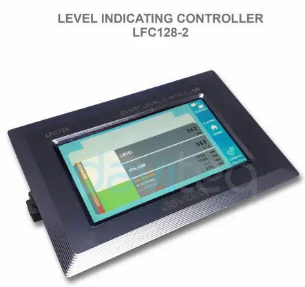
Controller LFC128-2
GIYA SA PAGGAMIT ALANG SA LEVEL NGA NAGPAILA SA CONTROLLER LFC128-2
LFC128-2-MN-EN-01 HUNYO-2020
LFC128-2 Advanced Level Display Controller
Kini nga dokumento gi-apply alang sa mosunod nga mga produkto
| SKU | LFC128-2 | HW Ver. | 1.0 | FW Ver. | 1.1 |
| Item Code | LFC128-2 | Level Indicating Controller, 4AI/DI, 4DI, 4xRelay, 1xPulse Output, 2 x RS485/ModbusRTU-Slave Communication | |||
Log sa Pagbag-o sa mga Function
| HW Ver. | FW Ver. | Petsa sa Pagpagawas | Mga gimbuhaton Pagbag-o |
| 1.0 | 1.1 | HUNYO-2020 | |
Pasiuna
Ang LFC128-2 usa ka advanced level display controller. Gihiusa sa produkto ang interface sa Modbus RTU aron matabangan ang PLC / SCADA / BMS ug ang bisan unsang pantalan sa IoT mahimong magkonektar sa pag-monitor. Ang LFC128-2 adunay usa ka yano apan kusgan nga disenyo nga adunay 4 AI / DI, 4 DI, 4 Relay, 1 Pulse pulse output, 2 RS485 Slave ModbusRTU nga nagtugot kanila sa pagkonektar sa daghang mga aparato nga dali. Uban sa advanced nga teknolohiya nga naghatag taas nga kalig-on ug kasaligan, daghang mga gimbuhaton, dali nga pag-install nga adunay touch screen ug mahigalaon nga interface makatabang sa biswal nga pagmonitor sa lebel.
Espesipikasyon
| Mga Digital nga Input | 04 x Ports, opto-coupler, 4.7 kohms input resisrtance, 5000V rms isolation, Logic 0 (0-1VDC), Logic 1 (5-24VDC), Functions: logic status 0/1 o Pulse counting (32 bit counter with max 4kHz pulse) |
| Mga Input sa Analog | 04 x Ports, pagpili tali sa 0-10VDC input o 0-20mA input, 12 bit Resolution, mahimong ma-configure isip Digital input pinaagi sa DIP switch (max 10VDC input) Ang AI1 port usa ka 0-10 VDC / 4-20 mA level sensor connection port |
| Relay Output | 04 x Ports, electro-mechanical Relays, SPDT, contact rating 24VDC/2A o 250VAC/5A, LED indicators |
| Pagbalhin sa Pulse | 01 x Ports, open-collector, opto-isolation, max 10mA ug 80VDC, On/off control, Pulser (max 2.5Khz, max 65535 Pulses) o PWM (max 2.5Khz) |
| Komunikasyon | 02 x ModbusRTU-Slave, RS485, speed 9600 o 19200, LED indicator |
| I-reset ang buton | Para sa pag-reset sa 02 x RS485 Slave port ngadto sa default setting (9600, None parity, 8 bit) |
| Type sa screen | Touch screen |
| suplay sa kuryente | 9..36VDC |
| Konsumo | 200mA @ 24VDC nga suplay |
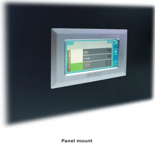
| Type sa pag-mount | Pagbutang sa panel |
| Pag-block sa Terminal | pitch 5.0mm, rating 300VAC, gidak-on sa wire 12-24AWG |
| Ang temperatura / kaumog sa pagtrabaho | 0..60 degC / 95% RH non-condensing |
| Dimensyon | H93xW138xD45 |
| Net gibug-aton | 390 gramos |
Mga Hulagway sa Produkto


Prinsipyo sa Operasyon

5.1 Modbus komunikasyon

02 x RS485/ModbusRTU-Slave
Protokol: Modbus RTU
adres: 1 – 247, 0 ang adres sa Broadcast
Baud rate: 9600, 19200
Paridad: wala, katingad-an, bisan
- LED indicator sa kahimtang:
- Gipangunahan sa: komunikasyon sa modbus OK
- Gipangunahan ang pagkidlap: nakadawat data apan ang komunikasyon sa modbus dili husto, tungod sa sayup nga pag-configure sa Modbus: adres, baudrate
- Gidala: Ang LFC128-2 walay nadawat nga datos, susiha ang koneksyon
Mga rehistro sa Memmap
Ang READ naggamit sa command 03, ang WRITE naggamit sa command 16
Default nga configuration:
- Adres: 1
- Baudrate nga ulipon 1: 9600
- Parity nga ulipon 1: wala
- Baudrate nga ulipon 2: 9600
- Parity nga ulipon 2: wala
| Pagrehistro sa Modbus | Hex adr | # sa mga rehistro |
Deskripsyon | Sakop | Default | Porma | Property | Komento |
| 0 | 0 | 2 | impormasyon sa device | LFC1 | hilo | Basaha | ||
| 8 | 8 | 1 | DI1 DI2: digital nga kahimtang | 0-1 | uint8 | Basaha | H_byte: DI1 L_byte: DI2 | |
| 9 | 9 | 1 | DI3 DI4: digital nga kahimtang | 0-1 | uint8 | Basaha | H_byte: DI3 L_byte: DI4 | |
| 10 | A | 1 | AI1 AI2: digital nga kahimtang | 0-1 | uint8 | Basaha | H_byte: AI1 L_byte: AI2 | |
| 11 | B | 1 | AI3 AI4: digital nga kahimtang | 0-1 | uint8 | Basaha | H_byte: AI3 L_byte: AI4 | |
| 12 | C | 1 | AI1: analog nga bili | uint16 | Basaha | |||
| 13 | D | 1 | AI2: analog nga bili | uint16 | Basaha | |||
| 14 | E | 1 | AI3: analog nga bili | uint16 | Basaha | |||
| 15 | F | 1 | AI4: analog nga bili | uint16 | Basaha | |||
| 16 | 10 | 2 | AI1: gi-scale nga bili | lutaw | Basaha | |||
| 18 | 12 | 2 | AI2: gi-scale nga bili | lutaw | Basaha | |||
| 20 | 14 | 2 | AI3: gi-scale nga bili | lutaw | Basaha | |||
| 22 | 16 | 2 | AI4: gi-scale nga bili | lutaw | Basaha | |||
| 24 | 18 | 1 | relay 1 | 0-1 | uint16 | Basaha | ||
| 25 | 19 | 1 | relay 2 | 0-1 | uint16 | Basaha | ||
| 26 | 1A | 1 | relay 3 | 0-1 | uint16 | Basaha | ||
| 27 | 1B | 1 | relay 4 | 0-1 | uint16 | Basaha | ||
| 28 | 1C | 1 | bukas nga kolektor ctrl | 0-3 | uint16 | Pagbasa/Pagsulat | 0: off 1: on 2: pwm, pulso padayon 3: pulso, kung igo nga numero sa pulso, ctrl = 0 | |
| 30 | 1E | 2 | kontra DI1 | uint32 | Pagbasa/Pagsulat | counter masulat, mapapas | ||
| 32 | 20 | 2 | kontra DI2 | uint32 | Pagbasa/Pagsulat | counter masulat, mapapas | ||
| 34 | 22 | 2 | kontra DI3 | uint32 | Pagbasa/Pagsulat | counter masulat, mapapas | ||
| 36 | 24 | 2 | kontra DI4 | uint32 | Pagbasa/Pagsulat | counter masulat, mapapas | ||
| 38 | 26 | 2 | kontra AI1 | uint32 | Pagbasa/Pagsulat | counter masulat, mapapas, max frequency 10Hz | ||
| 40 | 28 | 2 | kontra AI2 | uint32 | Pagbasa/Pagsulat | counter masulat, mapapas, max frequency 10Hz | ||
| 42 | 2A | 2 | kontra AI3 | uint32 | Pagbasa/Pagsulat | counter masulat, mapapas, max frequency 10Hz | ||
| 44 | 2C | 2 | kontra AI4 | uint32 | Pagbasa/Pagsulat | counter masulat, mapapas, max frequency 10Hz | ||
| 46 | 2E | 2 | DI1: oras na | uint32 | Pagbasa/Pagsulat | sec | ||
| 48 | 30 | 2 | DI2: oras na | uint32 | Pagbasa/Pagsulat | sec | ||
| 50 | 32 | 2 | DI3: oras na | uint32 | Pagbasa/Pagsulat | sec | ||
| 52 | 34 | 2 | DI4: oras na | uint32 | Pagbasa/Pagsulat | sec | ||
| 54 | 36 | 2 | AI1: oras na | uint32 | Pagbasa/Pagsulat | sec | ||
| 56 | 38 | 2 | AI2: oras na | uint32 | Pagbasa/Pagsulat | sec | ||
| 58 | 3A | 2 | AI3: oras na | uint32 | Pagbasa/Pagsulat | sec | ||
| 60 | 3C | 2 | AI4: oras na | uint32 | Pagbasa/Pagsulat | sec | ||
| 62 | 3E | 2 | DI1: pahulay | uint32 | Pagbasa/Pagsulat | sec | ||
| 64 | 40 | 2 | DI2: pahulay | uint32 | Pagbasa/Pagsulat | sec | ||
| 66 | 42 | 2 | DI3: pahulay | uint32 | Pagbasa/Pagsulat | sec | ||
| 68 | 44 | 2 | DI4: pahulay | uint32 | Pagbasa/Pagsulat | sec | ||
| 70 | 46 | 2 | AI1: walay pahulay | uint32 | Pagbasa/Pagsulat | sec | ||
| 72 | 48 | 2 | AI2: walay pahulay | uint32 | Pagbasa/Pagsulat | sec | ||
| 74 | 4A | 2 | AI3: walay pahulay | uint32 | Pagbasa/Pagsulat | sec | ||
| 76 | 4C | 2 | AI4: walay pahulay | uint32 | Pagbasa/Pagsulat | sec | ||
| 128 | 80 | 2 | kontra DI1 | uint32 | Basaha | counter dili makasulat, papason | ||
| 130 | 82 | 2 | kontra DI2 | uint32 | Basaha | counter dili makasulat, papason | ||
| 132 | 84 | 2 | kontra DI3 | uint32 | Basaha | counter dili makasulat, papason | ||
| 134 | 86 | 2 | kontra DI4 | uint32 | Basaha | counter dili makasulat, papason | ||
| 136 | 88 | 2 | kontra AI1 | uint32 | Basaha | counter dili makasulat, papason; max frequency 10Hz | ||
| 138 | 8A | 2 | kontra AI2 | uint32 | Basaha | counter dili makasulat, papason; max frequency 10Hz | ||
| 140 | 8C | 2 | kontra AI3 | uint32 | Basaha | counter dili makasulat, papason; max frequency 10Hz | ||
| 142 | 8E | 2 | kontra AI4 | uint32 | Basaha | counter dili makasulat, papason; max frequency 10Hz | ||
| 256 | 100 | 1 | modbus address nga ulipon | 1-247 | 1 | uint16 | Pagbasa/Pagsulat |
|
| 257 | 101 | 1 | modbus baudrate nga ulipon 1 | 0-1 | 0 | uint16 | Pagbasa/Pagsulat |
0: 9600, 1: 19200 |
| 258 | 102 | 1 | modbus parity nga ulipon 1 | 0-2 | 0 | uint16 | Pagbasa/Pagsulat |
0: wala, 1: katingad-an, 2: bisan |
5.2 I-reset ang Butang
Kung gigunitan ang reset button sulod sa 4 segundos, ang LFC 128-2 mag-reset sa default configuration ngadto sa 02 x RS485 / Modbus
RTU-Ulipon.
Default nga Modbus RTU Configuration:
- Adres: 1
- Rate sa Baud: 9600
- Parity: wala
5.3 Digital nga Input

Detalye:
- 04 channels DI, gilain
- Pagsukol sa Input: 4.7 kΏ
- Pagbulag Voltage: 5000vrms
- Logic nga lebel 0: 0-1V
- Logic nga lebel 1: 5-24V
- Kalihokan:
- Basaha ang lohika 0/1
- Pulse Counter
5.3.1 Basaha ang lohikal nga kahimtang 0/1
Logic value sa Modbus Memory Map: 0-1
Nagrehistro sa pagtipig sa mga bili sa lohika sa Modbus Memory Map:
- DI1__DI2: digital status: nagtipig sa lohikal nga kahimtang sa channel 1 ug channel 2.
H_byte: DI1
L_byte: DI2 - DI3__DI4: digital status: tipigi ang lohikal nga kahimtang sa channel 3 ug channel 4.
H_byte: DI3
L_byte: DI4
5.3.2 Pulse Counter
Counter value sa Modbus Memory Map, kung idugang ang numero nga molapas sa threshold, kini awtomatikong mobalik: 0 4294967295 (32bits)
Ang rehistro nga nagtipig sa Counter nga kantidad sa Modbus Memory Map dili mapapas:
- Counter DI1: nagtipig sa lohika nga kahimtang sa channel 1
- Counter DI2: nagtipig sa lohika nga kahimtang sa channel 2
- Counter DI3: tipigi ang logic state sa channel 3
- Counter DI4: nagtipig sa lohika nga kahimtang sa channel 4
Ang rehistro nga nagtipig sa Counter nga kantidad sa Modbus Memory Map dili mapapas: - Walay reset counter DI1: nagtipig sa logic nga kahimtang sa channel 1
- Walay reset counter DI2: nagtipig sa logic nga kahimtang sa channel 2
- Walay reset counter DI3: nagtipig sa logic nga kahimtang sa channel 3
- Walay reset counter DI4: nagtipig sa logic nga kahimtang sa channel 4
Pulse Counter Mode:
Ubos nga tulin nga ihap sa pulso ubos sa 10Hz nga adunay filter, anti-jamming:
- Itakda ang rehistro nga "counter DI1: oras sa pagsala" = 500-2000: Ang Channel 1 nag-ihap sa mga pulso nga ubos sa 10Hz
- Itakda ang rehistro nga "counter DI2: oras sa pagsala" = 500-2000: Ang Channel 2 nag-ihap sa mga pulso nga ubos sa 10Hz
- Itakda ang rehistro nga "counter DI3: oras sa pagsala" = 500-2000: Ang Channel 3 nag-ihap sa mga pulso nga ubos sa 10Hz
- Itakda ang rehistro nga "counter DI4: oras sa pagsala" = 500-2000: Ang Channel 4 nag-ihap sa mga pulso nga ubos sa 10Hz
- Taas nga tulin nga ihap sa pulso nga adunay max 2KHz frequency nga walay filter:
- Itakda ang rehistro nga "counter DI1: oras sa pagsala" = 1: ang channel 1 nag-ihap sa mga pulso nga adunay Fmax = 2kHz
- Itakda ang rehistro nga "counter DI2: oras sa pagsala" = 1: ang channel 2 nag-ihap sa mga pulso nga adunay Fmax = 2kHz
- Itakda ang rehistro nga "counter DI3: oras sa pagsala" = 1: ang channel 3 nag-ihap sa mga pulso nga adunay Fmax = 2kHz
- Itakda ang rehistro nga "counter DI4: oras sa pagsala" = 1: ang channel 4 nag-ihap sa mga pulso nga adunay Fmax = 2kHz
5.4 Analog nga Input
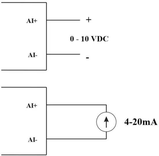
04 AI channels, walay isolation (AI1 kay 4-20mA / 0-5 VDC / 0-10 VDC level sensor input)
Gamita ang DIP SW aron ma-configure ang Analog input: 0-10V, 0-20mA
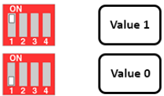
| Bili | Uri sa AI |
| 0 | 0-10 V |
| 1 | 0-20 mA |
Uri sa input:
- Sukdanan voltagug: 0-10V
- Sukda ang kasamtangan: 0-20mA
- Ang pagsumpo alang sa AI nagbasa sa parehas nga lohikal nga kahimtang sama sa DI, apan wala kini nahimulag nga adunay pulso nga range nga 0-24V
Input impedance:
- Sukdanan voltage: 320 kΏ
- Sukda ang kasamtangan: 499 Ώ
5.4.1 Basaha ang Analog nga bili
Resolusyon 12 tipik
Non-Linearity: 0.1%
Analog value sa Modbus Memory Map: 0-3900
Analog value register sa Modbus Memory Map:
- AI1 analog value: tipigi ang Analog value sa channel 1
- AI2 analog value: nagtipig sa Analog value sa channel 2
- AI3 analog value: tipigi ang Analog value sa channel 3
- AI4 analog value: tipigi ang Analog value sa channel 4
5.4.2 AI configuration naglihok sama sa DI
Walay pag-inusara
AI I-configure ang AI aron mabasa ang parehas nga kahimtang sa lohika sama sa DI nga adunay pulso ampLitud gikan sa 0-24V
Adunay 2 counter threshold AIx: logic threshold 0 ug counter AIx: threshold logic 1 sa modbus table: 0-4095
- Analog Analog bili sa AI
- Analog Analog value sa AI> counter AIx: threshold logic 1: giisip nga Logic 1 state of AI
- Counter AIx: threshold logic 0 =
Logic Logical status value sa AI sa Modbus Memory Map table: 0-1
Ang rehistro nagtipig sa lohikal nga mga kantidad sa Modbus Memory Map:
- AI1___AI2: digital status: nagtipig sa lohikal nga kahimtang sa channel 1 ug channel 2.
H_byte: AI1
L_byte: AI2 - AI3___AI4: digital status: nagtipig sa lohikal nga kahimtang sa channel 1 ug channel 2.
H_byte: AI3
L_byte: AI4
5.4.3 Pulse Counter AI max 10Hz
Counter value sa Modbus Memory Map, kung idugang ang numero lapas sa threshold, kini awtomatikong mobalik: 0 4294967295 (32bits)
Ang rehistro nga nagtipig sa Counter nga kantidad sa Modbus Memory Map dili mapapas:
- Counter AI1: nagtipig sa lohika nga kahimtang sa channel 1
- Counter AI2: i-save ang logic nga kahimtang sa channel 2
- Counter AI3: i-save ang logic nga kahimtang sa channel 3
- Counter AI4: i-save ang logic nga kahimtang sa channel 4
Ang rehistro nga nagtipig sa Counter nga kantidad sa Modbus Memory Map dili mapapas: - Walay reset counter AI1: nagtipig sa logic nga kahimtang sa channel 1
- Walay reset counter AI2: nagtipig sa logic nga kahimtang sa channel 2
- Walay reset counter AI3: nagtipig sa logic nga kahimtang sa channel 3
- Walay reset counter AI4: save logic state of channel 4
5.5 Relay
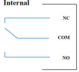
04 channel Relay SPDT NO / NC
Rating sa kontak: 2A / 24VDC, 0.5A / 220VAC
Adunay mga status LED:
- Gipangunahan sa: Close Contact
- Gipalong: Open Contact
| Default nga Relay Register | Ang kahimtang sa mga relay kung gi-reset ang mga suplay sa kuryente |
| 3 | Pag-opera sumala sa configuration sa Alarm |
Pag-configure sa Alarm:
- HIHI : Relay 4 On
- HI : Relay 3 On
- LO : Relay 2 On
- LOLO: Relay 1 On
5.6 Pulse Output

01 gilain nga open-collector channel
Opto-coupler: Tinubdan sa kasamtangan nga Imax = 10mA, Vceo = 80V
Mga gimbuhaton: On / Off, pulse generator, PWM
5.6.1 On/Off nga Function
Ibutang ang Open-collector register sa Modbus Memory Map table:
- Itakda ang Open-collector register: 1 => Pulse Output ON
- Itakda ang Open-collector register: 0 => Pulse Output OFF
5.6.2 Pulse generator
Ang output sa pulso nagpadala sa labing taas nga 65535 nga mga pulso, nga adunay Fmax nga 2.5kHz
I-configure ang mosunod nga mga rehistro sa lamesa sa Modbus Memory Map:
- Itakda ang rehistro nga “open collector: pulse number”: 0-65535 => Pulse Number = 65535: broadcast 65535 pulses
- Itakda ang rehistro nga “open collector: time cycle”: (0-65535) x0.1ms => Time Cycle = 4: Fmax 2.5kHz
- Itakda ang rehistro nga “open collector: time on”: (0-65535) x0.1ms => Time On: mao ang logic time 1 sa pulso
- Ibutang ang rehistro nga "open collector ctrl" = 3 => i-configure ang Pulse Output aron makamugna og pulse ug magsugod sa pulso, makamugna og igong gidaghanon sa mga pulso sa "open collector: pulse number" register => stop pulse generator ug register " open collector ctrl "= 0
5.6.3 PWM
Max frequency 2.5kHz
I-configure ang mosunod nga mga rehistro sa lamesa sa Modbus Memory Map:
- Ibutang ang rehistro nga "open collector ctrl" = 2 => i-configure ang Pulse Output PWM function
- Itakda ang rehistro nga “open collector: time cycle”: (0-65535) x0.1ms => Time Cycle = 4: Fmax 2.5kHz
- Itakda ang rehistro nga “open collector: time on”: (0-65535) x0.1ms => Time On: mao ang logic time 1 sa pulso
Pag-instalar
6.1 Pamaagi sa pag-instalar
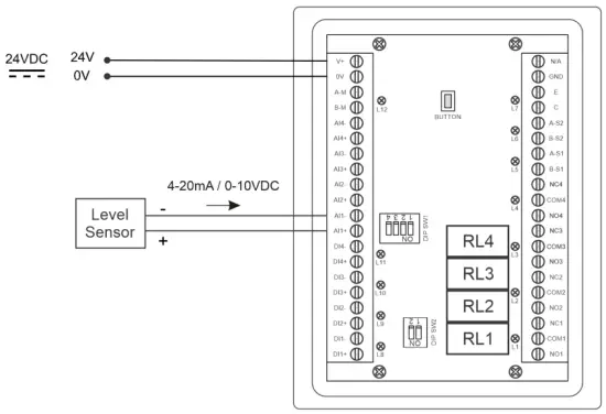
 6.2 Wiring nga adunay Level Sensor

Pag-configure
7.1 Screen sa Balay

LAKAS: Pagbalhin sa 2nd screen nga adunay mas detalyado nga kasayuran
Mga ALARMA: Ipakita ang Alerto sa Antas
PANAHON: Balik sa Home Screen
CONFIG. (Default nga Password: a): Adto sa Setting Screen
7.2 Setting screen (Default nga Password: a)
7.2.1 Screen 1
![daviteq LFC128 2 Advanced Level Display Controller - Home Screen 1] '](https://manuals.plus/wp-content/uploads/2025/08/daviteq-LFC128-2-Advanced-Level-Display-Controller-Home-Screen-1-550x305.png)
Mga ADC: Hilaw nga kantidad sa signal sa channel AI1
Level (Yunit): Ang lebel katumbas sa signal sa ADC pagkahuman sa pag-configure
Ang lebel sa mga Desimal nga Dapit:Decimal nga gidaghanon sa mga digit human sa tulbok sa Level 0-3 (00000, 1111.1, 222.22, 33.333)
lebel sa yunit: lebel nga mga yunit, 0-3 (0: mm, 1: cm, 2: m, 3: pulgada)
Sa 1: Isulod ang ADC value human ibutang ang 4 mA / 0 VDC ngadto sa AI1 para sa calibration sa 0 level
Scale 1: Ang lebel nga kantidad nga gipakita katumbas sa kantidad nga gisulod sa Sa 1 (kasagaran 0)
Sa 2: Pagsulod sa bili sa ADC human ibutang ang 20 mA / 10 VDC ngadto sa AI1 para sa pag-calibrate sa Tibuok nga lebel
Scale 2: Ang lebel nga kantidad nga gipakita katumbas sa kantidad nga gisulod sa Sa 2
Span nga lebel: Kinatas-ang bili sa Level (Span Level ≥ Scale 2)
Dami sa mga Desimal nga Dapit: Desimal nga gidaghanon sa mga digit human sa tulbok sa Volume 0-3 (00000, 1111.1, 222.22, 33.333)
Volume sa Yunit: mga yunit sa volume 0-3 (0: lit, 1: cm, 2: m3, 3:%)
7.2.2 Screen 2

Level Hi Hi Set point (Yunit): Taas nga Taas nga lebel sa Alarm nga lebel
Level Hi Hi Hys (Yunit): Taas nga High level hysteresis sa Alarm Level
Level Hi Set point (Yunit): Taas nga lebel sa Alarm Level
Level Hi Hys (Yunit): Taas nga lebel hysteresis sa Alarm Level
Level Lo Set point (Yunit): Ubos nga lebel sa Alarm Level
Level Lo Hys (Yunit): Ubos nga lebel hysteresis sa Alarm Level
Level Lo Lo Set point (Yunit): Ubos Ubos nga lebel sa Alarm Level
Level Lo Lo Hys (Yunit): Ubos Ubos nga lebel hysteresis sa Alarm Level
Mode sa Alarm: 0: Level, 1: Tomo
Span Volume(Yunit): Pinakataas nga kantidad sa volume
7.2.3 Screen 3

Volume Hi Hi Set point (Yunit): Taas nga Taas nga Volume sa Alarm Volume
Volume Hi Hi Hys (Yunit): Taas nga High volume hysteresis sa Alarm Volume
Volume Hi Set point (Yunit): Taas nga volume sa Alarm Volume
Volume Hi Hys (Yunit): Taas nga volume hysteresis sa Alarm Volume
Volume Lo Set point (Yunit): Ubos nga volume sa Alarm Volume
Volume Lo Hys (Yunit): Ubos nga volume hysteresis sa Alarm Volume
Volume Lo Lo Set point (Yunit): Ubos Ubos nga volume sa Alarm Volume
Tomo Lo Lo Hys (Yunit): Ubos Ubos nga volume hysteresis sa Alarm Volume
Kinatibuk-ang Pagdagan: Pagdalagan ang kinatibuk-ang function. 0-1 (0: Dili 1: Oo)
7.2.4 Screen 4

Pagpuno (Yunit): Kinatibuk-ang function: kinatibuk-ang gibutang sa tangke
Konsumo (Yunit): Total function: kinatibuk-ang konsumo sa tangke
Mga Desimal nga Dapit Total: Desimal nga gidaghanon sa mga parameter Pagpuno, Pagkonsumo, Pagpuno sa NRT, Pagkonsumo sa NRT sa display nga panid (dili ang panid sa setting)
Delta Total (Yunit): Hysteresis nga lebel sa kinatibuk-ang function
Adres sa Modbus: Modbus adres sa LFC128-2, 1-247
Modbus Baurate S1: 0-1 (0 : 9600 , 1 : 19200)
Modbus Parity S1: 0-2 (0: wala, 1: katingad-an, 2: bisan)
Modbus Baurate S2: 0-1 (0 : 9600 , 1 : 19200)
Modbus Parity S2: 0-2 (0: wala, 1: katingad-an, 2: bisan)
Numero sa mga Punto: Gidaghanon sa mga punto sa lamesa nga i-convert gikan sa lebel ngadto sa gidaghanon, 1-166
7.2.5 Screen 5

Point 1 Level (Level Unit): Level sa Point 1
Punto 1 Tomo (Volume Unit): Ang katugbang nga gidaghanon sa Point 1
Point 166 Level (Level Unit): Ang lebel sa gasolina sa Point 166
Punto 166 Tomo (Volume Unit): Ang katugbang nga gidaghanon sa Point 166
7.2.6 Screen 6

password: Password sa pagsulod sa pahina sa Setting, 8 ASCII nga mga karakter
Ngalan sa Tank: Ang ngalan sa tangke gipakita sa main screen
Pag-troubleshoot
| Dili. | Mga panghitabo | Rason | Mga solusyon |
| 1 | Ang Modbus napakyas sa pagpakigsulti | Status sa Modbus LED: Gipalong ang LED: walay nadawat nga data Nagkidlap-kidlap ang LED: dili husto ang configuration sa Modbus | Susiha ang koneksyon Susiha ang Modbus configuration: Address, Baud Rate, Parity |
| 2 | Timeout nga Modbus | Ang kasaba makita sa linya | I-configure ang Baudrate 9600 ug gamita ang twisted pair cable nga adunay proteksyon nga anti-jamming |
| 3 | Giputol ang Sensor | Ang sensor ug LFC128 nawad-an sa koneksyon | Pagsusi sa koneksyon Susihon ang tipo sa sensor (LFC128-2 nagkonektar lamang sa 0-10VDC / 4- 20mA analog sensor type) Susiha ang switch aron makita kung kini gi-on sa husto Susihon nga ang sensor connector husto AI1 |
| 4 | Kasaypanan sa linearization table | Sayop sa lamesa sa pagkakabig gikan sa lebel hangtod sa gidaghanon | Susiha ang configuration sa lamesa sa pagkakabig gikan sa lebel ngadto sa gidaghanon |
Suportahi ang mga kontak
Manufacturer
Daviteq Technologies Inc
No.11 Street 2G, Nam Hung Vuong Res., An Lac Ward, Binh Tan Dist., Ho Chi Minh City, Vietnam.
Tel: +84-28-6268.2523/4 (ext.122)
Email: info@daviteq.com
www.daviteq.com
Mga Dokumento / Mga Kapanguhaan
 |
daviteq LFC128-2 Advanced Level Display Controller [pdf] Manwal sa Instruksyon LFC128-2, LFC128-2 Advanced nga Level Display Controller, Advanced Level Display Controller, Level Display Controller, Display Controller |