![]() ED-CM4IO Industrial Embedded Computer
ED-CM4IO Industrial Embedded Computer
User Manual
ED-CM4IO COMPUTER
AN INDUSTRIAL EMBEDDED COMPUTER BASED ON RASPBERRY PI CM4
Shanghai EDA Technology Co.,Ltd
2023-02-07
ED-CM4IO Industrial Embedded Computer
Copyright Statement
ED-CM4IO Computer and its related intellectual property rights are owned by Shanghai EDA Technology Co., Ltd.
Shanghai EDA Technology Co., Ltd. owns the copyright of this document and reserves all rights. Without the written permission of Shanghai EDA Technology Co., Ltd, no part of this document may be modified, distributed or copied in any way or form.
Disclaimers
Shanghai EDA Technology Co., Ltd does not guarantee that the information in this hardware manual is up to date, correct, complete or of high quality. Shanghai EDA Technology Co., Ltd also does not guarantee the further use of this information. If the material or non-material related losses are caused by using or not using the information in this hardware manual, or by using incorrect or incomplete information, as long as it is not proved that it is the intention or negligence of Shanghai EDA Technology Co., Ltd, the liability claim for Shanghai EDA Technology Co., Ltd. can be exempted. Shanghai EDA Technology Co., Ltd expressly reserves the right to modify or supplement the contents or part of this hardware manual without special notice.
| Date | Version | Description | Note |
| 2/7/2023 | V1.0 | Initial version | |
Product Overview
ED-CM4IO Computer is a commercial industrial computer based on Compute Module 4 IO Board and CM4 module.
1.1 Target Application
- industrial applications
- Advertising display
- Intelligent manufacture
- Maker develop
1.2 Specifications and Parameters
| Function | Parameters |
| CPU | Broadcom BCM2711 4 core, ARM Cortex-A72(ARM v8), 1.5GHz, 64bit CPU |
| Memory | 1GB / 2GB / 4GB / 8GB option |
| eMMC | 0GB / 8GB / 16GB / 32GB option |
| SD card | micro SD card, support CM4 Lite without eMMC |
| Ethernet | 1x Gigabit Ethernet |
| WiFi / Bluetooth | 2.4G / 5.8G Dual band WiFi, bluetooth5.0 |
| HDMI | 2x standard HDMI |
| DSI | 2x DSI |
| Camera | 2x CSI |
| USB Host | 2x USB 2.0 Type A, 2x USB 2.0 Host Pin Header extended, 1x USB micro-B for eMMC burning |
| PCIe | 1-lane PCIe 2.0, Highest support 5Gbps |
| 40-Pin GPIO | Raspberry Pi 40-Pin GPIO HAT extended |
| Real time clock | 1x RTC |
| One-button on-off | Software on/off based on GPIO |
| Fan | 1x adjustable speed fan control interface |
| DC power supply output | 5V@1A, 12V@1A, |
| LED indicator | red(power indicator), green(system state indicator) |
| Power input | 7.5V-28V |
| Function | Parameters |
| Dimensions | 180(length) x 120(wide) x 36(high) mm |
| Case | Full Metal Shell |
| Antenna accessory | Support optional WiFi/BT external antenna, which has passed wireless authentication together with Raspberry Pi CM4, and optional 4G external antenna. |
| Operation system | Compatible with official Raspberry Pi OS, provides BSP software support package, and supports online installation and update of APT. |
1.3 System Diagram

1.4 Functional Layout

| No. | Function | No. | Function |
| A1 | CAM1 port | A13 | 2× USB port |
| A2 | DISP0 port | A14 | Ethernet RJ45 port |
| A3 | DISP1 port | A15 | POE port |
| A4 | CM4 Config Pin Header | A16 | HDMI1 port |
| A5 | CM4 socket | A17 | HDMI0 port |
| A6 | External power output port | A18 | RTC battery socket |
| A7 | Fan control port | A19 | 40 Pin Header |
| A8 | PCIe port | A20 | CAM0 port |
| A9 | 2× USB Pin Header | A21 | I2C-0 connect Pin Header |
| A10 | DC power socket | ||
| A11 | Micro SD slot | ||
| A12 | Micro USB port |
1.5 Packing List
- 1x CM4 IO Computer host
- 1x 2.4GHz/5GHz WiFi/BT antenna
1.6 Order Code

Quick Start
Quick start mainly guides you on how to connect devices, install systems, first-time startup configuration and network configuration.
2.1 Equipment List
- 1x ED-CM4IO Computer
- 1x 2.4GHz/5GHz WiFi/BT dual antenna
- 1x 12V@2A adapter
- 1x CR2302 button battery (RTC power supply)
2.2 Hardware Connection
Take the CM4 version with eMMC and supporting WiFi as an example to demonstrate how to install it.
In addition to the ED-CM4IO host, you also need:
- 1x Network cable
- 1x HDMI display
- 1x standard HDMI to HDMI cable
- 1x keyboard
- 1x mouse
- Install the WiFi external antenna.。
- Insert the network cable into the Gigabit network port, and the network cable is connected to network devices such as routers and switches that can access the Internet.
- Plug in the mouse and keyboard into USB port.
- Plug in the HDMI cable and connect the monitor.
- Power the 12V@2A power adapter and plug it into the DC power input port of ED-CM4IO Computer (labeled +12V DC).
2.3 First Start
The ED-CM4IO Computer is plugged into the power cord, and the system will start to boot.
- The red LED lights up, which means the power supply is normal.
- The green light starts flashing, indicating that the system starts normally, and then the logo of Raspberry will appear in the upper left corner of the screen.
2.3.1 Raspberry Pi OS (Desktop)
After the Desktop version of the system is started, directly enter the desktop.
If you use the official system image, and the image is not configured before burning, the Welcome to Raspberry Pi application will pop up and guide you to complete the initialization setting when you start it for the first time. 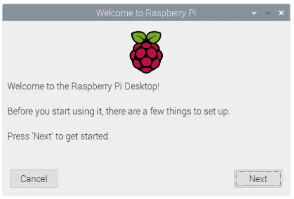
- Click Next to start the setup.
- Setting Country, Language and Timezone, click Next。
NOTE: You need to select a country region, otherwise the default keyboard layout of the system is the English keyboard layout (our domestic keyboards are generally the American keyboard layout), and some special symbols may not be typed.
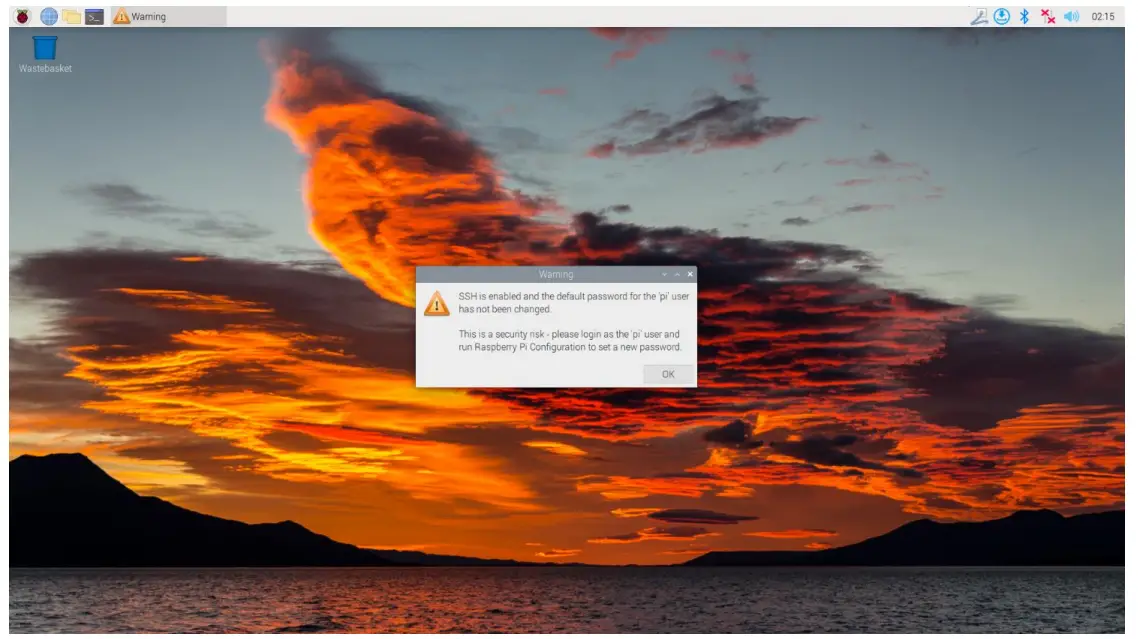
- Input a new password for the default account pi, and click Next.
NOTE: default password is raspberry
- Select the wireless network you need to connect to, enter the password, and then click Next.
 NOTE: If your CM4 module does not have a WIFI module, there will be no such step.
NOTE: Before upgrading the system, you need to wait for the wife connection to be normal (the wife icon appears in the upper right corner). - Click Next, and the wizard will automatically check and update Raspberry Pi OS.

- Click Restart to complete the system update.

2.3.2 Raspberry Pi OS (Lite)
If you use the system image provided by us, after the system starts, you will automatically log in with the user name pi, and the default password is raspberry.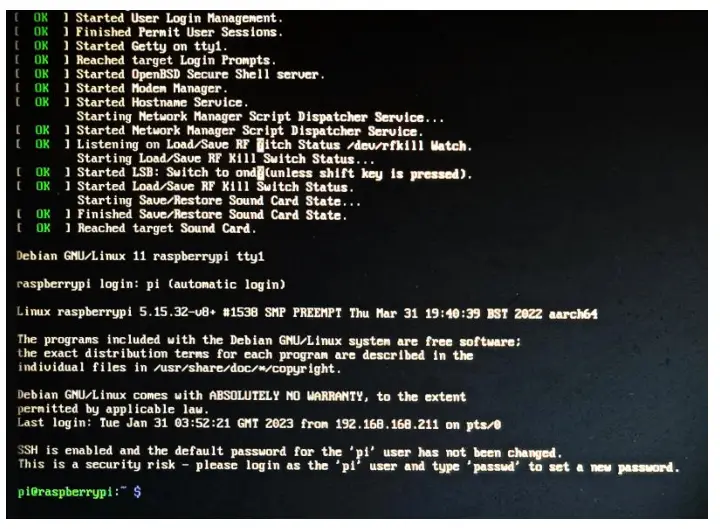
If you use the official system image, and the image is not configured before burning, the configuration window will appear when you start it for the first time. You need to configure the keyboard layout, set the user name and the corresponding password.
- Set the configuration keyboard layout

- Create new user name

Then set the password corresponding to the user according to the prompt, and enter the password again for confirmation. At this point, you can log in with the user name and password you just set.
2.3.3 Enable SSH
All the images we provide have turned on the SSH function. If you use the official image, you need to turn on the SSH function.
2.3.3.1 Use configuration Enable SSH
sudor raspy-config
- Choose 3 Interface Options
- Choose I2 SSH
- Would you like the SSH server to be enabled? Select Yes
- Choose Finish
2.3.3.2 Add Empty File To Enable SSH
Put an empty file named ssh in the boot partition, and the SSH function will be automatically enabled after the device is powered on.
2.3.4 Get The Device IP
- If the display screen is connected, you can use the ipconfig command to find the current device IP.
- If there is no display screen, you can view the assigned IP through the router.
- If there is no display screen, you can download the nap tool to scan the IP under the current network.
Nap supports Linux, macOS, Windows and other platforms. If you want to use neap to scan the network segments from 192.168.3.0 to 255, you can use the following command:
naps 192.168.3.0/24
After waiting for a period of time, the result will be output.
Starting Nap 7.92 ( https://nmap.org ) at 2022-12-30 21:19
Nap scan report for 192.168.3.1 (192.168.3.1)
Host is up (0.0010s latency).
MAC Address: XX:XX:XX:XX:XX:XX (Picohm (Shanghai))
Nmap scan report for DESKTOP-FGEOUUK.lan (192.168.3.33) Host is up (0.0029s latency).
MAC Address: XX:XX:XX:XX:XX:XX (Dell)
Nmap scan report for 192.168.3.66 (192.168.3.66) Host is up.
Nmap done: 256 IP addresses (3 hosts up) scanned in 11.36 seconds
Wiring Guide
3.1 Panel I/O
3.1.1 micro-SD Card
There is a micro SD card slot on the ED-CM4IO Computer. Please insert the micro SD card face up into the micro SD card slot.
3.2 Internal I/O
3.2.1 DISP
DISP0 and DISP1, use a 22-pin connector with a spacing of 0.5 mm. Please use FPC cable to connect them, with the foot surface of the metal pipe facing down and the substrate surface facing up, and the FPC cable is inserted perpendicular to the connector.
3.2.2 CAM
CAM0 and CAM1 both use 22-pin connectors with a spacing of 0.5 mm. Please use FPC cable to connect them, with the foot surface of the metal pipe facing down and the substrate surface facing up, and the FPC cable is inserted perpendicular to the connector.
3.2.3 Fan Connection
The fan has three signal wires, black, red and yellow, which are respectively connected to pins 1, 2 and 4 of J17, as shown below. 

3.2.4 Power ON-OFF Button Connection
The power on-off button of ED-CM4IO Computer has two red and black signal wires, the red signal wire is connected with PIN3 pin of 40PIN socket, and the black signal wire corresponds to GND, and can be connected with any pin of PIN6, PIN9, PIN14, PIN20, PIN25, PIN30, PIN34 and PIN39.
Software Operation Guide
4.1 USB 2.0
ED-CM4IO Computer has 2 USB2.0 interfaces. In addition, there are two USB 2.0 Host which are led out by 2×5 2.54mm Pin Header, and the socket is screen printed as J14. Customers can expand USB Device devices according to their own applications.
4.1.1 Check USB Device Information
List USB device
subs
The information displayed is as follows:
Bus 002 Device 001: ID 1d6b:0003 Linux Foundation 3.0 root hub
Bus 001 Device 005: ID 1a2c:2d23 China Resource Semco Co., Ltd Keyboard
Bus 001 Device 004: ID 30fa:0300 USB OPTICAL MOUSE
Bus 001 Device 003: ID 0424:9e00 Microchip Technology, Inc. (formerly SMSC)
LAN9500A/LAN9500Ai
Bus 001 Device 002: ID 1a40:0201 Terminus Technology Inc. FE 2.1 7-port Hub
Bus 001 Device 001: ID 1d6b:0002 Linux Foundation 2.0 root hub
4.1.2 USB Storage Device Mounting
You can connect an external hard disk, SSD or USB stick to any USB port on Raspberry Pi and mount the file system to access the data stored on it.
By default, your Raspberry Pi will automatically mount some popular file systems, such as FAT, NTFS and HFS+, in the location of /media/pi/HARD-DRIVE-LABEL.
In general, you can directly use the following commands to mount or unmount external storage devices.
lubok
NAME MAJ:MIN RM SIZE RO TYPE MOUNTPOINT
sad 8:0 1 29.1G 0 disk
└─sda1 8:1 1 29.1G 0 part
mmcblk0 179:0 0 59.5G 0 disk
├─mmcblk0p1 179:1 0 256M 0 part /boot
└─mmcblk0p2 179:2 0 59.2G 0 part /
Use the mount command to mount sda1 to the /mint directory. After the mount is completed, users can directly operate storage devices in the /mint directory.
sudor mount /dev/sda1 /mint
After the access operation is completed, use the command unmount to uninstall the storage device.
sudor unmount /mint
4.1.2.1 Mount
You can install the storage device in a specific folder location. It is usually done in the /mint folder, such as /mint/mudiks. Please note that the folder must be empty.
- Insert the storage device into the USB port on the device.
- Use the following command to list all disk partitions on Raspberry Pi: sudor lubok -o UUID,NAME,FSTYPE,SIZE,MOUNTPOINT,LABEL,MODEL
Raspberry Pi uses mount points / and /boot. Your storage device will appear in this list, along with any other connected storage devices. - Use the SIZE, LABLE and MODEL columns to identify the name of the disk partition that points to your storage device. For example, sda1.
- The FSTYPE column contains file system types. If your storage device uses the exeats file system, please install the exeats driver: sudor apt update sudor apt install exeat-fuse
- If your storage device uses NTFS file system, you will have read-only access to it. If you want to write to the device, you can install the ntfs-3g driver:
sudor apt update sudor apt install ntfs-3g - Run the following command to get the location of the disk partition: sudor balked like, /dev/sda1
- Create a target folder as the mount point of the storage device. The mount point name used in this example is mydisk. You can specify a name of your choice:
sudor midair /mint/mudiks - Mount the storage device at the mount point you created: sudor mount /dev/sda1 /mint/mudiks
- Verify that the storage device has been successfully mounted by listing the following: ls /mint/mudiks
WARN:If there is no desktop system, external storage devices will not be automatically mounted.
4.1.2.2 Unmount
When the device is turned off, the system will unmount the storage device so that it can be pulled out safely. If you want to uninstall the device manually, you can use the following command: sudo umount /mint/mydisk
If you receive a “destination busy” error, it means that the storage device has not been unmounted. If no error is displayed, you can safely unplug the device now.
4.1.2.3 Set up automatic mount in the command line You can modify the festal setting to mount automatically.
- First, you need to get the disk UUID.
sudo blkid - Find the UUID of the mounted device, such as 5C24-1453.
- Open festal file sudo nano /etc/festal
- Add the following to the festal file UUID=5C24-1453 /mnt/mydisk stipe defaults,auto,users,rw,nofail 0 0 Replace stipe with the type of your file system, which you can find in step 2 of “Mounting storage devices” above, for example, nets.
- If the file system type is FAT or NTFS, add unmask = 000 immediately after onfall, which will allow all users to have full read/write access to every file on the storage device.
You can use man festal to find more information about festal commands.
4.2 Ethernet Configuration
4.2.1 Gigabit Ethernet
There is an adaptive 10/100/1000Mbsp Ethernet interface on ED-CM4IO Computer, and it is recommended to use Cat6 (Category 6) network cable to cooperate with it. By default, the system uses DHCP to automatically obtain IP. The interface supports PoE and has ESD protection. PoE signal introduced from RJ45 connector is connected to the pin of J9 socket.
NOTE:Because PoE module only provides +5V power supply and cannot generate +12V power supply, PCIe expansion cards and fans will not work when using PoE power supply.
4.2.2 Using The Network Manager To Configure
If you use the desktop image, it is recommended to install the Network Manager plug-in network manager-gnome. After installation, you can directly configure the network through the desktop icon. sudo apt update sudo apt install network-manager-gnome sudo reboot
NOTE: If use our factory image, the network-manager tool and the network-manager-gnome plug-in are installed by default.
NOTE: If use our factory image, the Network Manager service is automatically started and the dhcpcd service is disabled by default.
After the installation is completed, you will see the Network Manager icon in the status bar of the system desktop.![]()
Right-click the Network Manager icon and select Edit Connections。
Select the connection name to modify, and then click the gear below.
Switch to the configuration page of IPv4 Settings. If you want to set static IP, the Method selects Manual, and Addresses the IP you want to configure. If you want to set it as dynamic IP acquisition, just configure the Method as Automatic(DHCP) and restart the device.
If you use the Raspberry Pi OS Lite, you can configure it through the command line.
If you want to use the command to set the static IP for the device, you can refer to the following methods.
set the static IP
sudo nuclei connection modify <name> ipv4.addresses 192.168.1.101/24 ipv4.method manual set the gateway
sudo nuclei connection modify <name> ipv4.gateway 192.168.1.1
Set dynamic IP acquisition
sudo nuclei connection modify <name> ipv4.method auto
4.2.3 Configuration With dhcpcd Tool
The official system of Raspberry Pi uses dhcpcd as the network management tool by default.
If you use the factory image provided by us and want to switch from Network Manager to dhcpcd network management tool, you need to stop and disable Network Manager service and enable dhcpcd service first.
sudo systemctl stop Network Manager
sudo systemctl disable Network Manager
sudo systemctl enable dhcpcd
sudo reboot
The dhcpcd tool can be used after the system is restarted.
Static IP can be set by modifying.etc.dhcpcd.com. For example, eth0 can be set, and users can set wlan0 and other network interfaces according to their different needs.
interface eth0
static ip_address=192.168.0.10/24
static routers=192.168.0.1
static domain_name_servers=192.168.0.1 8.8.8.8 fd51:42f8:caae:d92e::1
4.3 WiFi
Customers can purchase ED-CM4IO Computer with WiFi version, which supports 2.4 GHz and 5.0 GHz IEEE 802.11 b/g/n/ac dual-band WiFi. We provide dual-band external antenna, which has passed wireless authentication together with Raspberry Pi CM4.
4.3.1 Enable WiFi
The WiFi function is blocked by default, so you need to set the country region before you can use it. If you use the desktop version of the system, please refer to the chapter: Initialization Settings Configure WiFi. If you use the Lite version of the system, please use configuration to set the WiFi country area. Please refer to the documentation.:”Raspberry Pi official documents – Using the Command Line”
4.3.1 Enable WiFi
The WiFi function is blocked by default, so you need to set the country region before you can use it. If you use the desktop version of the system, please refer to the chapter: Initialization Settings Configure WiFi. If you use the Lite version of the system, please use raspy-config to set the WiFi country area. Please refer to the documentation.:”Raspberry Pi official documents – Using the Command Line”
sudo nuclei device wifi
Connect WiFi with password.
sudo nuclei device wifi connect <SSID> password <password>
Set up WiFi automatic connection
sudo nuclei connection modify <name> connection.autoconnect yes
4.3.1.2 Configure Using dhcpcd
The official system of Raspberry Pie uses dhcpcd as the network management tool by default.
sudo raspy-config
- Choose 1 System Options
- Choose S1 Wireless LAN
- Choose your country in Select the country in which the Pi is to be used ,than choose OK,This prompt only appears when setting up WIFI for the first time.
- Please enter SSID,input WIFI SSID
- Please enter passphrase. Leave it empty if none,input password than restart the device
4.3.2 External Antenna and Internal PCB Antenna
You can switch whether to use an external antenna or a built-in PCB antenna through software configuration. Considering compatibility and widest support, the factory default system is the built-in PCB antenna. If the customer chooses a complete machine with a shell and is equipped with an external antenna, you can switch by the following operations:
Edit /boot/config.txt
sudo nano /boot/config.txt
Choose external add
Dataram=ant2
Then restart to take effect.
4.3.3 AP and Bridge Mode
ED-CM4IO Computer’s Wifi also supports configuration in AP router mode, bridge mode or mixed mode.
Please refer to the open source project github:garywill/linux-router to learn how to configure it.
4.4 Bluetooth
ED-CM4IO Computer can choose whether the Bluetooth function is integrated or not. If it is equipped with Bluetooth, this function is turned on by default.
Bluetooth can be used to scan, pair and connect Bluetooth devices. Please refer to the ArchLinuxWiki-Bluetooth guide to configure and use Bluetooth.
4.4.1 Usage
Scan:bluetoothctl scan on/off
Find:bluetoothctl discoverable on/off
Trust device:bluetoothctl trust [MAC]
Connect device:bluetoothctl connect [MAC]=
Disconnect device:bluetoothctl disconnect [MAC]
4.4.2 Example
Into Bluetooth shell
sudo bluetoothctl
Enable Bluetooth
power on
Scan device
scan on
Discovery started
[CHG] Controller B8:27:EB:85:04:8B Discovering: yes
[NEW] Device 4A:39:CF:30:B3:11 4A-39-CF-30-B3-11
Find the name of the turned-on Bluetooth device, where the name of the turned-on Bluetooth device is test.
devices
Device 6A:7F:60:69:8B:79 6A-7F-60-69-8B-79
Device 67:64:5A:A3:2C:A2 67-64-5A-A3-2C-A2
Device 56:6A:59:B0:1C:D1 Lafon
Device 34:12:F9:91:FF:68 test
Pair device
pair 34:12:F9:91:FF:68
Attempting to pair with 34:12:F9:91:FF:68
[CHG] Device 34:12:F9:91:FF:68 Services Resolved: yes
[CHG] Device 34:12:F9:91:FF:68 Paired: yes
Pairing successful
Add as trusted device
trust 34:12:F9:91:FF:68
[CHG] Device 34:12:F9:91:FF:68 Trusted: yes
Changing 34:12:F9:91:FF:68 trust succeeded
4.5 RTC
The ED-CM4IO Computer is integrated with RTC and uses CR2032 button cell. RTC chip is mounted on i2c-10 bus.
Enabling I2C bus of RTC needs to be configured in config.txt
Dataram=i2c_vc=on
NOTE:The address of RTC chip is 0x51.
We provide an automatic synchronization BSP package for RTC, so you can use RTC without feeling. If you install the official system of Raspberry Pie, you can install the “ed-retch” package. Please refer to the detailed installation process Install BSP Online Based On The Original Raspberry Pi OS.
The principle of RTC automatic synchronization service is as follows:
- When the system is turned on, the service automatically reads the saved time from RTC and synchronizes it to the system time.
- If there is an Internet connection, the system will automatically synchronize the time from the NTP server and update the local system time with Internet time.
- When the system is shut down, the service automatically writes the system time into RTC and updates the RTC time.
- Because of the installation of button cell, although the CM4 IO Computer is powered off, the RTC is still working and timing.
In this way, we can ensure that our time is accurate and reliable.
If you don’t want to use this service, you can turn it off manually:
sudo systemctl disable retch
sudo reboot
Re-enable this service:
sudo systemctl enable retch
sudo reboot
Read RTC Time manually:
sudo hemlock -r
2022-11-09 07:07:30.478488+00:00
Manually synchronize RTC time to the system:
sudo hemlock -s
Write the system time into RTC:
sudo hemlock -w
4.6 Power ON/OFF Button
ED-CM4IO Computer has the function of one-button power on/off. Forcibly turning off the power supply during the operation may damage the file system and cause the system to crash. One-button power on/off is realized by combining Raspberry Pi’s Bootloader and 40PIN’s GPIO through software, which is different from the traditional power on/off by hardware.
One-button power on/off uses GPIO3 on the 40-pin socket. If you want to realize the one-button power on/off function, this pin should be configured as ordinary GPIO function, and can no longer be defined as SCL1 of I2C. Please remap I2C function to other pins.
When the +12V input power supply is connected, pressing the key continuously will trigger the CM4 module to turn off and on alternately.
NOTE:To realize the one-button on-off function, it is necessary to install the factory image or the BSP package provided by us.
4.7 LED Indication
ED-CM4IO Computer has two indicator lights, the red LED is connected with the LED_PI_nPWR pin of CM4, which is the power indicator light, and the green LED is connected with the LED_PI_nACTIVITY pin of CM4, which is the running status indicator light.
4.8 Fan Control
CM4 IO Computer supports PWM drive and speed control fan. The fan power supply is +12V, which comes from the +12V input power supply.
The chip of fan controller is mounted on i2c-10 bus. To enable I2C bus of fan controller, it needs to be configured in config.txt
Dataram=i2c_vc=on
NOTE:The address of the fan controller chip on I2C bus is 0x2f.
4.8.1 Install The Fan Control Package
First, install the fan BSP package ed-cm4io-fan through apt-get. Please refer to for details Install BSP Online Based On The Original Raspberry Pi OS.
4.8.2 Set Fan Speed
After installing ed-cm4io-fan, you can use the set_fan_range command and the nonmanual command to automatically configure and manually set the fan speed.
- Automatic control of fan speed
The set_fan_range command sets the temperature range. Below the lower temperature limit, the fan stops working, and above the upper temperature limit, the fan runs at full speed.
set_fan_range -l [low] -m [mid] -h [high] Set the fan monitoring temperature range, low temperature is 45 degrees, medium temperature is 55 degrees, and high temperature is 65 degrees.
set_fan_range -l 45 -m 55 -h 65
When the temperature is lower than 45 ℃, the fan stops output.
When the temperature is higher than 45 ℃ and lower than 55 ℃, the fan will output at 50% speed.
When the temperature is higher than 55 ℃ and lower than 65 ℃, the fan will output at 75% speed.
When the temperature is higher than 65 ℃, the fan will output at 100% speed. - Manually set the fan speed.
#Stop the fan control service first
sudo systemctl stop fan_control.service
#Manually set the fan speed, and then enter the parameters as prompted.
fanmanual
Operating system installation
5.1 Image Download
We have provided the factory image. If the system is restored to factory settings, please click the
following link to download the factory image.
Raspberry Pi OS With Desktop, 64-bit
– Release date: Dec 09th 2022
– System: 64-bit
– Kernel version: 5.10
– Debian version: 11 (bullseye)
– Release notes
– Downloads: https://1drv.ms/u/s!Au060HUAtEYBco9DinOio2un5wg?e=PQkQOI
5.2 eMMC Flash
EMMC burning is required only when CM4 is a non-Lite version.
- Download and install rpiboot_setup.exe
- Download and install Raspberry Pi Imager or balenaEtcher
If the installed CM4 is a non-Lite version, the system will burn to eMMC:
- Open the upper cover of CM4IO Computer.
- Connect the Micro USB data cable with J73 interface (screen printed as USB PROGRAM).
- Start the rainboot tool just installed on the Windows PC side, and the default path is C:\Program Files (x86)\Raspberry Pi\rpiboot.exe。
- When the CM4IO Computer is powered on, the CM4 eMMC will be recognized as a mass storage device.
- Use the image burning tool to burn your image to the identified mass storage device.
5.3 Install BSP Online Based On The Original Raspberry Pi OS
BSP package provides support for some hardware functions, such as SPI Flash, RTC, RS232, RS485, CSI, DSI, etc. Customers can use the image of our pre-installed BSP package or install the BSP package themselves.
We support installing and updating BSP through apt-get, which is as simple as installing some other software or tools.
- First, download the GPG key and add our source list.
curl -sass https://apt.edatec.cn/pubkey.gpg | sudo apt-key add -echo “deb https://apt.edatec.cn/raspbian stable main” | sudo tee/etc/apt/sources.list.d/edatec.list - Then, install the BSP package
sudo apt update
sudo apt install ed-cm4io-fan ed-retch - Install the Network Manager network management tool [optional]
Network Manager tools can more easily configure routing rules and set priorities.
# If you use the Raspberry Pi OS Lite version system.
sudo apt install ed-network manager
# If you use a system with a desktop, we recommend that you install the plug-in sudo apt install ed-network manager-gnome - reboot
sudo reboot
FAQ
6.1 Default username and password
For the image we provide, the default user name is pi, and the default password is raspberry.
About us
7.1 About EDATEC
EDATEC, located in Shanghai, is one of Raspberry Pi’s global design partners. Our vision is to provide hardware solutions for Internet of Things, industrial control, automation, green energy and artificial intelligence based on Raspberry Pi technology platform.
We provide standard hardware solutions, customized design and manufacturing services to speed up the development and time to market of electronic products.
7.2 Contact us
Mail – sales@edatec.cn / support@edatec.cn
![]() Phone – +86-18621560183
Phone – +86-18621560183
Website – https://www.edatec.cn
Address – Room 301, Building 24, No.1661 Jealous Highway, Jiading District, Shanghai
Documents / Resources
 |
EDA TEC ED-CM4IO Industrial Embedded Computer [pdf] User Manual ED-CM4IO, ED-CM4IO Industrial Embedded Computer, Industrial Embedded Computer, Embedded Computer, Computer |


