![]() T-Format Interface v1.1 User Guide
T-Format Interface v1.1 User Guide
Introduction (Ask a Question)
The T-Format interface IP has been designed to provide an interface for the FPGAs to communicate with various compliant Tamagawa products such as rotary encoders.
Summary (Ask a Question)
The following table provides a summary of the T-Format interface characteristics.
Table 1. T-Format Interface Characteristics
| Core Version | This document applies to T-Format Interface v1.1. |
| Supported Device Families |
|
| Supported Tool Flow | Requires Libero® SoC v11.8 or later releases. |
| Licensing | Complete encrypted RTL code is provided for the core, enabling the core to be instantiated with SmartDesign. Simulation, Synthesis, and Layout are performed with Libero software. T-Format Interface is licensed with encrypted RTL that must be purchased separately. For more information, see T-Format Interface. |
Features (Ask a Question)
T-Format Interface has the following key features:
- Transmits and receives serial data from the physical layer (RS-485 interface)
- Aligns data as per T-Format and provides this data as registers that are read by subsequent blocks
- Checks for errors, such as parity, Cyclic Redundancy Check (CRC) mismatch, transmit errors, and so on, are reported by the external device
- Provides an alarm function that is triggered if the number of fault occurrences exceeds a configured threshold
- Provides ports for an external CRC generator block so that the user modifies the CRC polynomial if necessary
Implementation of IP Core in Libero Design Suite (Ask a Question)
IP core must be installed to the IP Catalog of the Libero SoC software. This is done automatically through the IP Catalog update function in the Libero SoC software, or the IP core is manually downloaded from the catalog. Once the IP core is installed in the Libero SoC software IP Catalog, the core is configured, generated, and instantiated within the Smart Design tool for inclusion in the Libero project list.
Device Utilization and Performance (Ask a Question)
The following table lists the device utilization used for T-Format Interface.
Table 2. T-Format Interface Utilization
| Device Details | Resources | Performance (MHz) | RAMs | Math Blocks | Chip Globals | |||
| Family | Device | LUTs | DFF | LSRAM | μSRAM | |||
| PolarFire® SoC | MPFS250T | 248 | 256 | 200 | 0 | 0 | 0 | 0 |
| PolarFire | MPF300T | 236 | 256 | 200 | 0 | 0 | 0 | 0 |
| SmartFusion® 2 | M2S150 | 248 | 256 | 200 | 0 | 0 | 0 | 0 |
Important:
 he data in this table is captured using typical synthesis and layout settings. CDR reference clock source was set to Dedicated with other configurator values unchanged.
- Clock is constrained to 200 MHz while running the timing analysis to achieve the performance numbers.
Functional Description (Ask a Question)
This section describes the implementation details of the T-Format Interface.
The following figure shows the top-level block diagram of the T-Format Interface.
Figure 1-1. Top Level Block Diagram of T-Format Interface IP
 For complete details on T-Format, see Tamagawa datasheets. The following table lists the various commands that are used to request data from the external device and their functions, and the number of data fields returned for each command.
Table 1-1. Commands for Control Field
| Command ID | Function | Number of Data Fields in Received Frame |
| 0 | Rotor Angle (Data Read) | 3 |
| 1 | Multiturn data (Data Read) | 3 |
| 2 | Encoder ID (Data Read) | 1 |
| 3 | Rotor Angle and Multiturn data (Data Read) | 8 |
| 7 | Reset | 3 |
| 8 | Reset | 3 |
| C | Reset | 3 |
The following figure shows the system-level block diagram of the T-Format Interface.
Figure 1-2. System-Level Block Diagram of T-Format Interface
 The following figure shows the functional block diagram of T-Format interface.
Figure 1-3. Functional Block Diagram of T-Format Interface IP
 Each communication transaction in T-Format starts with a transmission of Control Frame (CF) from the requestor, followed by a frame received from the external device. The TF Transmitter block generates serial data to be sent to the external device. It also generates an optional tx_en_o signal required by some RS-485 converters. The encoder receives the data transmitted, and transmits a frame of serial data to the IP, which is received in the rx_i input port of the IP block. The TF_CF_DET block first detects the control field and identifies the ID value. The data length is determined based on the received ID value, and subsequent fields are received and stored in respective registers using the TF_DATA_READ block. After the complete data is stored, the data in all fields except the CRC field is sent to an external CRC generator block, and the calculated CRC generated by this block is compared to the CRC received. Someof the other errors are also checked, and the done_o signal is asserted (‘1’ for one sys_clk_i cycle) after every error free transaction.
1.1 Error Handling (Ask a Question)
The block identifies the following errors:
- Parity error in the received control field
- Bad start sequence in received control field
- Incomplete message where the RX line is stuck at 0 or stuck at 1
- CRC mismatch between data in received CRC field, and calculated CRC
- Transmit Errors such as parity error or delimiter error in transmitted CF, as read from bit 6 and bit 7 of the status field (see Tamagawa datasheet).
These errors, when identified by the block, result in a fault counter getting incremented. When the fault counter value exceeds the configured threshold value (configured using g_FAULT_THRESHOLD), the alarm_o output is asserted.
The alarm output is deasserted when the alarm_clr_i input is high for one sys_clk_i period. The tf_error_o signal is used to display the type of error that has occurred. This data is reset to 0, when the next transaction begins (start_i is
‘1’).
The following table describes various errors and their corresponding bit position in the tf_error_o register.
Table 1-2. terrors Register Description
| Bit | Function |
| 5 | TX delimiter error – as indicated in bit 7 of status field |
| 4 | TX parity error – as indicated in bit 6 of status field |
| 3 | CRC mismatch between CRC field received from slave and calculated CRC data |
| 2 | Incomplete message – delimiter error resulting in timeout |
| 1 | Bad start sequence in received control field – “0010” not received before timeout |
| 0 | Parity Error in received control field |
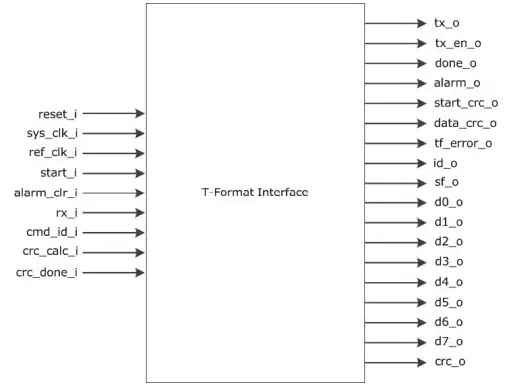
T-Format Interface Parameters and Interface Signals (Ask a Question)
This section discusses the parameters in the T-Format Interface GUI configurator and I/O signals.
2.1 Configuration Settings(Ask a Question)
The following table lists the description of the configuration parameters used in the hardware implementation of T-Format Interface. These are generic parameters and are varied as per the requirement of the application.
Table 2-1. Configuration Parameter
| Signal Name | Description |
| g_TIMEOUT_TIME | Defines the timeout time between successive fields in a frame in multiples of sys_clk_i period. |
| g_FAULT_THRESHOLD | Defines the fault threshold value – alarm_o is asserted when the fault counter exceeds this value. |
2.2 Inputs and Outputs Signals (Ask a Question)
The following table lists the input and output ports of T-Format Interface.
Table 2-2. Inputs and Outputs of T-Format Interface
| Signal Name | Direction | Description |
| reset_i | Input | Active low asynchronous reset signal to design |
| sys_clk_i | Input | System Clock |
| ref_clk_i | Input | Reference clock, 2.5MHz* |
| start_i | Input | Startsignal to start T-Format transaction – must be ‘1’ for one sys_clk_i cycle |
| alarm_clr_i | Input | Clearalarm signal – must be ‘1’ for one sys_clk_i cycle |
| rx_i | Input | Serialdata input from encoder |
| crc_done_i | Input | Donesignal from external CRC block –must be ‘1’ for one sys_clk_i cycle |
| cmd_i | Input | ControlField ID to be sent to encoder |
| crc_calc_i | Input | Outputof CRC Generator block with bits reversed, that is, crc_gen(7) -> crc_calc_i (0), crc_gen(6)-> crc_calc_i(1), .. crc_gen(0)-> crc_calc_i(7) |
| tx_o | Output | Serial data output to encoder |
| tx_en_o | Output | Transmit enable signal – goes high when transmission is in progress |
| done_o | Output | Transaction done signal – asserted as a pulse with a width of one sys_clk_i cycle |
| alarm_o | Output | Alarm signal – asserted when the number of fault occurrences equals the threshold value configured in g_FAULT_THRESHOLD |
| start_crc_o | Output | Start signal for CRC generation block |
| data_crc_o | Output | Datafor CRC generation block – data is provided as: {CF, SF, D0, D1, D2, .. D7} without delimiters. In case of shorter messages (where only D0-D2 have data), the other fields D3-D7 are taken as 0 |
| tf_error_o | Output | TF Error register |
| id_o | Output | ID value from control field in received frame* |
| sf_o | Output | Status field from received frame* |
| d0_o | Output | D0field from received frame* |
| d1_o | Output | D1field from received frame* |
| d2_o | Output | D2field from received frame* |
| d3_o | Output | D3field from received frame* |
| d4_o | Output | D4field from received frame* |
| d5_o | Output | D5field from received frame* |
| d6_o | Output | D6field from received frame* |
| d7_o | Output | D7field from received frame* |
| crc_o | Output | CRC field from received frame* |
Note: For more information, see the Tamagawa datasheet.
Timing Diagrams (Ask a Question)
This section discusses T-Format Interface timing diagrams.
The following figure shows a normal T-Format transaction. The done_o signal is generated at the end of every error free transaction, and the tf_error_o signal remains at 0.
Figure 3-1. Timing Diagram – Normal Transaction
 The following figure shows a T-Format transaction with CRC error. The done_o signal is not generated, and the tf_error_o signal is 8, indicating that a CRC mismatch has occurred. The done_o signal is generated if the next transaction does not have any error.
Figure 3-2. Timing Diagram – CRC Error

Testbench (Ask a Question)
A unified test-bench is used to verify and test T-Format Interface called as user test-bench. Testbench is provided to check the functionality of the T-Format Interface IP.
4.1 Simulation (Ask a Question)
The following steps describe how to simulate the core using the testbench:
- Open the Libero SoC application, click Libero SoC Catalog tab, expand Solutions-MotorControl
- Double-click T-Format Interface, and then click OK. The documentation associated with the IP are listed under Documentation.
Important: If you do not see the Catalog tab, navigate to View Windows menu and click Catalog to make it visible.
Figure 4-1. T-Format Interface IP Core in Libero SoC Catalog
- On the Stimulus Hierarchy tab, right-click testbench ( t_format_interface_tb.v), point to Simulate Pre-Synth Design, and then click Open Interactively.
Important: If you do not see the Stimulus Hierarchy tab, navigate to View > Windows menu and click Stimulus Hierarchy to make it visible.
Figure 4-2. Simulating Pre-Synthesis Design

ModelSim opens with the testbench file as shown in the following figure.
Figure 4-3. ModelSim Simulation Window

![]() Important: If the simulation is interrupted due to the runtime limit specified in the .do file, use the run -all command to complete the simulation.
Important: If the simulation is interrupted due to the runtime limit specified in the .do file, use the run -all command to complete the simulation.
Revision History (Ask a Question)
The revision history describes the changes that were implemented in the document. The changes are listed by revision, starting with the most current publication.
Table 5-1. Revision History
| Revision | Date | Description |
| A | 02/2023 | The following is the list of changes in revision A of the document: • Migrated the document to the Microchip template. • Updated the document number to DS50003503A from 50200812. • Added 3. Timing Diagrams. • Added 4. Testbench. |
| 1.0 | 02/2018 | Revision 1.0 was the first publication of this document. |
Microchip FPGA Support (Ask a Question)
Microchip FPGA products group backs its products with various support services, including Customer Service, Customer Technical Support Center, a website, and worldwide sales offices. Customers are suggested to visit Microchip online resources prior to contacting support as it is very likely that their queries have been already answered.
Contact Technical Support Center through the website at www.microchip.com/support. Mention the FPGA Device Part number, select appropriate case category, and upload design files while creating a technical support case.
Contact Customer Service for non-technical product support, such as product pricing, product upgrades, update information, order status, and authorization.
- From North America, call 800.262.1060
- From the rest of the world, call 650.318.4460
- Fax, from anywhere in the world, 650.318.8044
Microchip Information (Ask a Question)
The Microchip Website(Ask a Question)
Microchip provides online support via our website at www.microchip.com/. This website is used to make files and information easily available to customers. Some of the content available includes:
- Product Support – Data sheets and errata, application notes and sample programs, design resources, user’s guides and hardware support documents, latest software releases and archived software
- General Technical Support – Frequently Asked Questions (FAQs), technical support requests, online discussion groups, Microchip design partner program member listing
- Business of Microchip – Product selector and ordering guides, latest Microchip press releases, listing of seminars and events, listings of Microchip sales offices, distributors and factory representatives
Product Change Notification Service (Ask a Question)
Microchip’s product change notification service helps keep customers current on Microchip products. Subscribers will receive email notification whenever there are changes, updates, revisions or errata related to a specified product family or development tool of interest.
To register, go to www.microchip.com/pcn and follow the registration instructions.
Customer Support (Ask a Question)
Users of Microchip products can receive assistance through several channels:
- Distributor or Representative
- Local Sales Office
- Embedded Solutions Engineer (ESE)
- Technical Support
Customers should contact their distributor, representative or ESE for support. Local sales offices are also available to help customers. A listing of sales offices and locations is included in this document.
Technical support is available through the website at: www.microchip.com/support
Microchip Devices Code Protection Feature (Ask a Question)
Note the following details of the code protection feature on Microchip products:
- Microchip products meet the specifications contained in their particular Microchip Data Sheet.
- Microchip believes that its family of products is secure when used in the intended manner, within operating specifications, and under normal conditions.
- Microchip values and aggressively protects its intellectual property rights. Attempts to breach the code protection features of Microchip product is strictly prohibited and may violate the Digital Millennium Copyright Act.
- Neither Microchip nor any other semiconductor manufacturer can guarantee the security of its code. Code protection does not mean that we are guaranteeing the product is “unbreakable”. Code protection is constantly evolving. Microchip is committed to continuously improving the code protection features of our products.
Legal Notice (Ask a Question)
This publication and the information herein may be used only with Microchip products, including to design, test, and integrate Microchip products with your application. Use of this information in any other manner violates these terms. Information regarding device applications is provided only for your convenience and may be superseded by updates. It is your responsibility to ensure that your application meets with your specifications. Contact your local Microchip sales office for additional support or, obtain additional support at www.microchip.com/en-us/support/design-help/client-support-services.
THIS INFORMATION IS PROVIDED BY MICROCHIP “AS IS”. MICROCHIP MAKES NO REPRESENTATIONS OR WARRANTIES OF ANY KIND WHETHER EXPRESS OR IMPLIED, WRITTEN OR ORAL, STATUTORY OR OTHERWISE, RELATED TO THE INFORMATION INCLUDING BUT NOT LIMITED TO ANY IMPLIED WARRANTIES OF NON-INFRINGEMENT, MERCHANTABILITY, AND FITNESS FOR A PARTICULAR PURPOSE, OR WARRANTIES RELATED TO ITS CONDITION, QUALITY, OR PERFORMANCE.
IN NO EVENT WILL MICROCHIP BE LIABLE FOR ANY INDIRECT, SPECIAL, PUNITIVE, INCIDENTAL, OR CONSEQUENTIAL LOSS, DAMAGE, COST, OR EXPENSE OF ANY KIND WHATSOEVER RELATED TO THE INFORMATION OR ITS USE, HOWEVER CAUSED, EVEN IF MICROCHIP HAS BEEN ADVISED OF THE POSSIBILITY OR THE DAMAGES ARE FORESEEABLE. TO THE FULLEST EXTENT ALLOWED BY LAW, MICROCHIP’S TOTAL LIABILITY ON ALL CLAIMS IN ANY WAY RELATED TO THE INFORMATION OR ITS USE WILL NOT EXCEED THE AMOUNT OF FEES, IF ANY, THAT YOU HAVE PAID DIRECTLY TO MICROCHIP FOR THE INFORMATION.
Use of Microchip devices in life support and/or safety applications is entirely at the buyer’s risk, and the buyer agrees to defend, indemnify and hold harmless Microchip from any and all damages, claims, suits, or expenses resulting from such use. No licenses are conveyed, implicitly or otherwise, under any Microchip intellectual property rights unless otherwise stated.
Trademarks (Ask a Question)
The Microchip name and logo, the Microchip logo, Adaptec, AVR, AVR logo, AVR Freaks, BesTime, BitCloud, CryptoMemory, CryptoRF, dsPIC, flexPWR, HELDO, IGLOO, JukeBlox, KeeLoq, Kleer, LANCheck, LinkMD, maXStylus, maXTouch, MediaLB, megaAVR, Microsemi, Microsemi logo, MOST, MOST logo, MPLAB, OptoLyzer, PIC, picoPower, PICSTART, PIC32 logo, PolarFire, Prochip Designer, QTouch, SAM-BA, SenGenuity, SpyNIC, SST, SST Logo, SuperFlash, Symmetricom, SyncServer, Tachyon, TimeSource, tinyAVR, UNI/O, Vectron, and XMEGA are registered trademarks of Microchip Technology Incorporated in the U.S.A. and other countries.
AgileSwitch, APT, ClockWorks, The Embedded Control Solutions Company, EtherSynch, Flashtec, Hyper Speed Control, HyperLight Load, Libero, motorBench, mTouch, Powermite 3, Precision Edge, ProASIC, ProASIC Plus, ProASIC Plus logo, Quiet- Wire, SmartFusion, SyncWorld, Temux, TimeCesium, TimeHub, TimePictra, TimeProvider, TrueTime, and ZL are registered trademarks of Microchip Technology Incorporated in the U.S.A. Adjacent Key Suppression, AKS, Analog-for-the-Digital Age, Any Capacitor, AnyIn, AnyOut, Augmented Switching, BlueSky, BodyCom, Clockstudio, CodeGuard, CryptoAuthentication, CryptoAutomotive, CryptoCompanion, CryptoController, dsPICDEM, dsPICDEM.net, Dynamic Average Matching, DAM, ECAN, Espresso T1S, EtherGREEN, GridTime, IdealBridge, In-Circuit Serial Programming, ICSP, INICnet, Intelligent Paralleling, IntelliMOS, Inter-Chip Connectivity, JitterBlocker, Knob-on-Display, KoD, maxCrypto, maxView, memBrain, Mindi, MiWi, MPASM, MPF, MPLAB Certified logo, MPLIB, MPLINK, MultiTRAK, NetDetach, Omniscient Code Generation, PICDEM, PICDEM.net, PICkit, PICtail, PowerSmart, PureSilicon, QMatrix, REAL ICE, Ripple Blocker, RTAX, RTG4, SAM-ICE, Serial Quad I/O, simpleMAP, SimpliPHY, SmartBuffer, SmartHLS, SMART-I.S., storClad, SQI, SuperSwitcher, SuperSwitcher II, Switchtec, SynchroPHY, Total Endurance, Trusted Time, TSHARC, USBCheck, VariSense, VectorBlox, VeriPHY, ViewSpan, WiperLock, XpressConnect, and ZENA are trademarks of Microchip Technology Incorporated in the U.S.A. and other countries.
SQTP is a service mark of Microchip Technology Incorporated in the U.S.A.
The Adaptec logo, Frequency on Demand, Silicon Storage Technology, and Symmcom are registered trademarks of Microchip Technology Inc. in other countries.
GestIC is a registered trademark of Microchip Technology Germany II GmbH & Co. KG, a subsidiary of Microchip Technology Inc., in other countries.
All other trademarks mentioned herein are property of their respective companies.
© 2023, Microchip Technology Incorporated and its subsidiaries. All Rights Reserved. ISBN: 978-1-6683-2140-9
Quality Management System (Ask a Question)
For information regarding Microchip’s Quality Management Systems, please visit www.microchip.com/quality.
Worldwide Sales and Service
| AMERICAS | ASIA/PACIFIC | ASIA/PACIFIC | EUROPE |
| Corporate Office 2355 West Chandler Blvd. Chandler, AZ 85224-6199 Tel: 480-792-7200 Fax: 480-792-7277 Technical Support: www.microchip.com/support Web Address: www.microchip.com Atlanta Duluth, GA Tel: 678-957-9614 Fax: 678-957-1455 Austin, TX Tel: 512-257-3370 Boston Westborough, MA Tel: 774-760-0087 Fax: 774-760-0088 Chicago Itasca, IL Tel: 630-285-0071 Fax: 630-285-0075 Dallas Addison, TX Tel: 972-818-7423 Fax: 972-818-2924 Detroit Novi, MI Tel: 248-848-4000 Houston, TX Tel: 281-894-5983 Indianapolis Noblesville, IN Tel: 317-773-8323 Fax: 317-773-5453 Tel: 317-536-2380 Los Angeles Mission Viejo, CA Tel: 949-462-9523 Fax: 949-462-9608 Tel: 951-273-7800 Raleigh, NC Tel: 919-844-7510 New York, NY Tel: 631-435-6000 San Jose, CA Tel: 408-735-9110 Tel: 408-436-4270 Canada – Toronto Tel: 905-695-1980 Fax: 905-695-2078 |
Australia – Sydney Tel: 61-2-9868-6733 China – Beijing Tel: 86-10-8569-7000 China – Chengdu Tel: 86-28-8665-5511 China – Chongqing Tel: 86-23-8980-9588 China – Dongguan Tel: 86-769-8702-9880 China – Guangzhou Tel: 86-20-8755-8029 China – Hangzhou Tel: 86-571-8792-8115 China – Hong Kong SAR Tel: 852-2943-5100 China – Nanjing Tel: 86-25-8473-2460 China – Qingdao Tel: 86-532-8502-7355 China – Shanghai Tel: 86-21-3326-8000 China – Shenyang Tel: 86-24-2334-2829 China – Shenzhen Tel: 86-755-8864-2200 China – Suzhou Tel: 86-186-6233-1526 China – Wuhan Tel: 86-27-5980-5300 China – Xian Tel: 86-29-8833-7252 China – Xiamen Tel: 86-592-2388138 China – Zhuhai Tel: 86-756-3210040 |
India – Bangalore Tel: 91-80-3090-4444 India – New Delhi Tel: 91-11-4160-8631 India – Pune Tel: 91-20-4121-0141 Japan – Osaka Tel: 81-6-6152-7160 Japan – Tokyo Tel: 81-3-6880- 3770 Korea – Daegu Tel: 82-53-744-4301 Korea – Seoul Tel: 82-2-554-7200 Malaysia – Kuala Lumpur Tel: 60-3-7651-7906 Malaysia – Penang Tel: 60-4-227-8870 Philippines – Manila Tel: 63-2-634-9065 Singapore Tel: 65-6334-8870 Taiwan – Hsin Chu Tel: 886-3-577-8366 Taiwan – Kaohsiung Tel: 886-7-213-7830 Taiwan – Taipei Tel: 886-2-2508-8600 Thailand – Bangkok Tel: 66-2-694-1351 Vietnam – Ho Chi Minh Tel: 84-28-5448-2100 |
Austria – Wels Tel: 43-7242-2244-39 Fax: 43-7242-2244-393 Denmark – Copenhagen Tel: 45-4485-5910 Fax: 45-4485-2829 Finland – Espoo Tel: 358-9-4520-820 France – Paris Tel: 33-1-69-53-63-20 Fax: 33-1-69-30-90-79 Germany – Garching Tel: 49-8931-9700 Germany – Haan Tel: 49-2129-3766400 Germany – Heilbronn Tel: 49-7131-72400 Germany – Karlsruhe Tel: 49-721-625370 Germany – Munich Tel: 49-89-627-144-0 Fax: 49-89-627-144-44 Germany – Rosenheim Tel: 49-8031-354-560 Israel – Ra’anana Tel: 972-9-744-7705 Italy – Milan Tel: 39-0331-742611 Fax: 39-0331-466781 Italy – Padova Tel: 39-049-7625286 Netherlands – Drunen Tel: 31-416-690399 Fax: 31-416-690340 Norway – Trondheim Tel: 47-72884388 Poland – Warsaw Tel: 48-22-3325737 Romania – Bucharest Tel: 40-21-407-87-50 Spain – Madrid Tel: 34-91-708-08-90 Fax: 34-91-708-08-91 Sweden – Gothenberg Tel: 46-31-704-60-40 Sweden – Stockholm Tel: 46-8-5090-4654 UK – Wokingham Tel: 44-118-921-5800 Fax: 44-118-921-5820 |
© 2023 Microchip Technology Inc.
and its subsidiaries
DS50003503A-page 18
Documents / Resources
 |
MICROCHIP T-Format Interface Software [pdf] User Guide MPF300T, T-Format Interface Software, Interface Software, Software |