![]() ENGINEERING TOMORROW
ENGINEERING TOMORROW
User Guide
Danfoss Gas Detection
Controller unit and
Expansion module 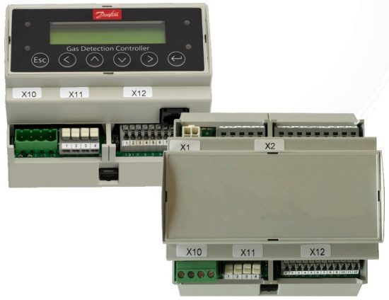
Intended use
The Danfoss gas detection controller unit is controlling one or multiple gas detectors, for monitoring, detection and warning of toxic and flammable gases and vapours in the ambient air. The controller unit meets the requirements according to EN 378 and the guidelines “Safety requirements for ammonia (NH3) refrigeration systems”.
The intended sites are all areas being directly connected to the public low voltage supply, e.g. residential, commercial and industrial ranges as well as small enterprises (according to EN 5502).
The controller unit may only be used in ambient conditions as specified in the technical data.
The controller unit must not be used in potentially explosive atmospheres.
Description
The controller unit is a warning and control unit for the continuous monitoring of different toxic or flammable gases and vapours as well as of HFC and HFO refrigerants. The controller unit is suitable for the connection of up to 96 digital sensors via the 2-wire bus. Up to 32 analog inputs for the connection of sensors with 4 to 20 mA signal interface are available in addition.
The controller unit can be employed as pure analog controller, as analog/digital or as digital controller. The total number of connected sensors, however, may not exceed 128 sensors.
Up to four programmable alarm thresholds are available for each sensor. For binary transmission of the alarms there are up to 32 relays with potential-free change-over contact and up to 96 signal relays.
Comfortable and easy operation of the controller unit is done via the logical menu structure.
A number of integrated parameters enables the realisation of various requirements in the gas measuring technique. Configuration is menu-driven via the keypad. For fast and easy configuration, you can use the PC based configuration software, included in the PC tool.
Prior to commissioning please consider the guidelines for wiring and commissioning of the hardware.
2.1 Normal Mode
In normal mode, the gas concentrations of the active sensors are continuously polled and displayed at the LC display in a scrolling way. In addition, the controller unit continuously monitors itself, its outputs and the communication to all active sensors and modules.
2.2 Alarm Mode
If the gas concentration reaches or exceeds the programmed alarm threshold, the alarm is started, the assigned alarm relay is activated and the alarm LED (light red for alarm 1, dark red for alarm 2 + n) starts to flash. The set alarm can be read from the menu Alarm Status.
When the gas concentration falls below the alarm threshold and the set hysteresis, the alarm is automatically reset. In latching mode, the alarm must be reset manually directly at the alarm triggering device after falling below the threshold.
This function is obligatory for flammable gases detected by catalytic bead sensors generating a falling signal at too high gas concentrations.
2.3 Special Status Mode
In the special status mode there are delayed measurements for the operation side, but no alarm evaluation. The special status is indicated on the display and it always activates the fault relay.
The controller unit adopts the special status when:
- faults of one or more active devices occur,
- the operation starts up after return of voltage (power on),
- the service mode is activated by the user,
- the user reads or changes parameters,
- an alarm or signal relay is manually overridden in the alarm status menu or via digital inputs.
2.3.1 Fault Mode
If the controller unit detects an incorrect communication of an active sensor or module, or if an analog signal is outside the admissible range (< 3.0 mA > 21.2 mA), or if there are internal function errors coming from the self-control modules incl. watchdog and voltage control, the assigned fault relay is set and the error LED starts to flash.
The error is displayed in the menu Error Status in clear text. After removal of the cause, the error message must be acknowledged manually in the menu Error Status.
2.3.2 Restart Mode (Warm-up Operation)
Gas detection sensors need a running-in period, until the chemical process of the sensor reaches stable conditions. During this running-in period the sensor signal can lead to an unwanted release of a pseudo alarm.
Depending on the connected sensor types, the longest warm-up time must be entered as poweron time in the controller.
This power-on time is started at the controller unit after switching on the power supply and/or after the return of voltage.
While this time is running out, the gas controller unit does not display any values and does not activate any alarms; the controller system is not yet ready for use.
The power-on status occurs on the first line of the starting menu.
2.3.3 Service Mode
This operation mode includes commissioning, calibration, testing, repair and decommissioning.
The service mode can be enabled for a single sensor, for a group of sensors as well as for the complete system. In active service mode pending alarms for the concerned devices are held, but new alarms are suppressed.
2.3.4 UPS Functionality
The supply voltage is monitored in all modes.
When reaching the battery voltage in the power pack, the UPS function of the controller unit is enabled and the connected battery is charged.
If the power fails, the battery voltage drops down and generates the power failure message.
At empty battery voltage, the battery is separated from the circuit (function of deep discharge protection).
When the power is restored, there will be an automatic return to the charging mode.
No settings and therefore no parameters are required for the UPS functionality.
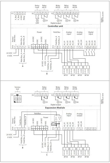
Wiring configuration
Operation
The complete configuration and service are made via keypad user interface in combination with the LC display screen. Security is provided via three password levels against unauthorized intervention.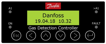
4.1 Function of the keys and LEDs on the keypad
| Exits programming, returns to the previous menu level. | |
| Enters sub menus, and saves parameter settings. | |
| Scrolls up & down within a menu, changes a value. | |
| Moves the cursor position. |
LED light red: Flashes when alarm one or more alarms are active.
LED dark red: Flashes when alarm two and alarms of higher priority are active.
LED yellow: Flashes at system or sensor failure or when maintenance date exceeded or in voltage-free status with the option power failure flashing light.
LED green: Power LED
| Open desired menu window. Code input field opens automatically, if no code is approved. |
|
| After input of valid code the cursor jumps onto the first position segment to be changed. | |
| Push the cursor onto the position segment, which has to be changed. | |
| Push the cursor onto the position segment, which has to be changed. | |
| Save the changed value, confirm storage (ENTER). | |
| Cancel storage / close editing / go back to next higher menu level (ESCAPE function). | |
4.3 Code Levels
According to the regulations of national and international standards for gas warning systems, all inputs and changes are protected by a four-digit numeric code (= password) against unauthorised intervention. The menu windows of status messages and measuring values are visible without entering a code.
The release of a code level is cancelled if no button is pushed within 15 minutes.
The code levels are classified in order of priority:
Priority 1 has top priority.
Priority 1: (code 5468, not changeable)
Code level priority 1 is intended for the service technician of the installer to change parameters and set-points. This password allows working on all settings. For opening the parameter menus you must first activate the service mode after code release.
Priority 2: (code 4009, not changeable)
With code level 2, it is possible to lock / unlock transmitters temporarily. This password is only given to the end user by the installer in problem situations. In order to lock / unlock the sensors you must first activate the service mode after code release.
Priority 3: (code 4321, is settable in the maintenance information menu)
It is only intended to update the maintenance date. Normally the code is only known by the service technician who has last changed it since it can be changed individually via priority 1.
Priority 4: (password 1234) (code not changeable)
Code level priority 4 allows the operator:
- to acknowledge faults,
- to set date and time,
- to configure and to operate the data logger option, after activation of the operation mode “Service Mode”:
- to read all parameters,
- to manually operate test function of the alarm relays (functional test of the connected units),
- to manually operate test function of the analog outputs (functional test of the connected units).
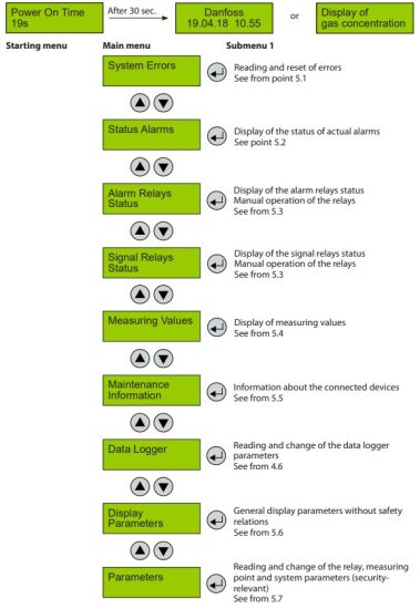
Menu operation is done via a clear, intuitive and logical menu structure. The operating menu contains the following levels:
- Starting menu with indication of the device type if no MP is registered, otherwise scrolling display of the gas concentrations of all registered sensors in 5-second intervals. If alarms are active, only the values of the sensors currently in alarm status are displayed.
- Main menu
- Submenu 1 to 3
5.1 Fault Management
The integrated fault management records the first 100 faults with date and time stamps in the menu „System Errors“. Additionally a record of the faults occurs in the “Error memory”, which can only be read and reset by the service technician A pending fault activates the fault indication relay. The yellow LED (Fault) starts to flash; the fault is displayed in plain text with date and time in the starting menu.
In case of the fault of a connected sensor the alarms defined in the menu “MP Parameter” are activated in addition.
5.1.1 Acknowledge a Fault
According to the directives of the gas measuring technique, accumulated errors are allowed to be acknowledged automatically. The automatic acknowledgment of a fault is only possible after having removed the cause!
5.1.2 Error Memory
The menu „Error Memory“ in the main menu “System Error” can only be opened via the code level priority 1.
In the error memory, the first 100 faults that have occurred and have already been acknowledged in the menu “System Error” are listed for the service technician in a power failure safe way.
Attention:
This memory should always be read during maintenance, relevant faults should be tracked and entered in the service logbook, and finally the memory should be emptied.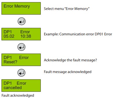
5.1.3 System Messages and Errors
| “AP 0X Overrange” | Current signal at analog input > 21.2 mA |
| Cause: | Short-circuit at analog input, analog sensor not calibrated, or defective. |
| Solution: | Check cable to analog sensor, make calibration, replace sensor. |
| “AP Underrange” | Current signal at analog input < 3.0 mA |
| Cause: | Wire break at analog input, analog sensor not calibrated, or defective. |
| Solution: | Check cable to analog sensor, make calibration, replace sensor. |
Any device with microprocessor and digital communication – such as digital heads, sensor boards, expansion modules and even the controller – is equipped with extensive self-monitoring systems and diagnostic functions.
They enable detailed conclusions about the error causes and help the installers and operators to quickly determine the cause, and/or to arrange an exchange.
These errors can only be transmitted when the connection to the central (or tool) is intact.
| “DP 0X Sensor Element” | (0x8001) Sensor element at the sensor head – diagnostic function reports an error. |
| Cause: | Sensor pins broken, mechanical or electrical damage |
| Solution: | Exchange sensor head. |
| “DP 0X ADC Error” | (0x8002) Monitoring of the amplifier and AD converter circuits at the input device reports an error. |
| Cause: | Mechanical or electrical damage of the amplifiers |
| Solution: | Replace device. |
| “DP 0X Voltage” | (0x8004) Monitoring of the sensor and/or process power supply, device reports an error. |
| Cause: | Mechanical or electrical damage of the power supply |
| Solution: | Measure tension if too low, replace device. |
| “DP 0X CPU Error” | (0x8008) Monitoring of the processor function – reports an error. |
| Cause: | Mechanical or electrical damage of the processor |
| Solution: | Replace device. |
| “DP 0x EE Error” | (0x8010) Monitoring of the data storage – reports an error. |
| Cause: | Electrical damage of the memory or configuration error |
| Solution: | Check configuration, replace device. |
| “DP 0X I/O Error” | (0x8020) Power ON or monitoring of the in/outputs of the processor reports an error. |
| Cause: | During restart, electrical damage of the processor or of circuit elements |
| Solution: | Wait until Power On is over, replace device. |
| “DP 0X Overtemp.” | (0x8040) Ambien temperature too high; the sensor outputs the measurement value for a determined period and switches to error state after 24 h. |
| Cause: | Too high ambient temperature |
| Solution: | Protect the device from direct sunlight or check climatic conditions. |
| “DP 0X Overrange” | (0x8200) Signal of sensor element at the sensor head is out of range. |
| Cause: | Sensor not calibrated correctly (e.g. wrong calibration gas), defective |
| Solution: | Recalibrate sensor, replace it. |
| “DP 0X Underrange” | (0x8100) Signal of sensor element at the sensor head is out of range. |
| Cause: | Wire break at sensor element input, sensor drift too high, defective. |
| Solution: | Recalibrate sensor, replace it. |
The controller monitors the communication between request and response. If the reply is too late, incomplete or incorrect, the controller recognizes the following errors and reports them.
| “SB 0X Error” | (0x9000) Communication error from central unit to SB (sensor board) |
| Cause: | Bus line interrupted or short circuit, DP 0X registered at the controller, but not addressed. SB 0X defective. |
| Solution: | Check line to SB 0X, check SB address or MP parameters, replace sensor. |
| “DP 0X Error” | (0xB000) Communication error of SB to DP 0X sensor |
| Cause: | Bus line between SB and head interrupted or short circuit, DP 0X registered at the controller, but not configured at SB, wrong gas type, DP 0X defective. |
| Solution: | Check line to DP 0X, check sensor address or parameters, replace sensor. |
| “EP_06 0X Error” | (0x9000) Communication error to EP_06 0X module (expansion module) |
| Cause: | Bus line interrupted or short circuit, EP_06 0X registered at the controller, but not addressed or addressed incorrectly, EP_06 0X module defective |
| Solution: | Check line to EP_06 0X, check module address, replace module. |
| “Maintenance” | (0x0080) System maintenance is due. |
| Cause: | Maintenance date exceeded. |
| Solution: | Perform the maintenance. |
| “DP XX locked” “AP XX locked” |
This MP input is locked (MP is physically present, but locked by the operator) |
| Cause: | Operator intervention. |
| Solution: | Eliminate the cause of a possible fault and then unlock the MP. |
| “UPS Error” | (0x8001) UPS doesn’t work correctly, can only be signaled by the GC. |
| Cause: | Defective UPS – too high or too low voltage |
| Solution: | Replace UPS. |
| “Power Failure” | (0x8004) can only be signaled by the GC. |
| Cause: | Power failure or fuse tripped. |
| Solution: | Check power supply or fuses. |
| “XXX FC: 0xXXXX” | Occurs, if there are several errors from one measuring point. |
| Cause: | Several causes |
| Solution: | See the specific errors. |
5.2 Status Alarm
Display of the currently pending alarms in plain text in the order of their arrival. Only those measuring points are displayed, where at least one alarm is active. The alarms are generated either in the controller (alarm) or directly on site in the sensor / module (local alarm).
Interventions are possible in this menu item only for the acknowledgment of latching alarms.
Pending alarms cannot be acknowledged.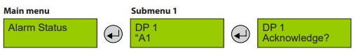
| Symbol | Description | Function |
| AP X | Measuring Point No. | Analog measuring point X = 1 – 32, where an alarm is pending. |
| DP X | Measuring Point No. | Digital measuring point X = 1 – 96, where an alarm is pending. |
| ‘A1 ‘‘A1 | Alarm status | ‘A1 = Local alarm 1 active (generated in the sensor / module) A1 = Alarm 1 active (generated in the central control) |
5.3 Relay Status
Reading of the current status of alarm and signal relays.
The manual operation (test function) of the alarm and signal relays is done in the menu Parameters.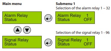 5.4 Menu Measuring Values
In this menu, the display shows the measuring value with gas type and unit. If the alarm evaluation is defined via the average, the display shows the current value (C) and additionally the average value (A).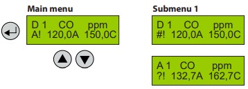
| Symbol | Description | Function |
| DX | Measured value | Measured value from bus sensor with MP address with X = 1 – 96 |
| AX | Measured value | Measured value from analog sensor at analog input with AX = 1 – 32 |
| CO | Gas type | See 4.7.3 |
| ppm | Gas unit | See 4.7.3 |
| A | Average value | Arithmetic average (30 measured values within the time unit) |
| C | Current value | Current value of gas concentration |
| A! | Alarm | MP has triggered an alarm |
| # | Maint. info | Device has exceeded maintenance date |
| ? | ConfigError | MP configuration not compatible |
| $ | Local mode | Local special mode is active |
| Error | Fault MP | Communication error, or signal out of the measuring range |
| Locked | MP locked | MP was temporarily locked by the operator. |
The information ConfigError has priority to maintenance information.
Alarm information is always displayed with „!“, even if ConfigError or maintenance information are active.
5.5 Maintenance Information
A control of the maintenance intervals required by law (SIL) or by the customer is integrated in the Controller system. When changing the maintenance intervals, you have to observe legal and normative regulations and the manufacturer’s specifications! Always after that, a calibration must be performed so that the change can take effect.
System maintenance message:
At commissioning or after successful maintenance, the date (battery backed) for next due maintenance of the whole system has to be entered. When this date has been reached, the maintenance message is activated.
Sensor maintenance message:
Sensors need regular calibration for complying with the specified accuracy and reliability. In order to avoid complex manual documentation, the sensors store their run time between the calibration intervals continuously and permanently. If the run time since the last calibration exceeds the sensor maintenance interval stored in the sensor, a maintenance message is sent to the central control.
The maintenance message is reset during calibration and the running time since the last calibration is set to zero.
Device reaction with pending maintenance message:
The maintenance signal can be ORed to each of the active relays in the menu Relay Parameters. In this way, one or more relays can be activated in case of maintenance (see 4.8.2.9).
In case of a pending maintenance message, the phone no. of the service company appears in the main menu instead of the time / date information and the yellow LED on the display starts to flash.
The maintenance message can only be cleared by removing the cause – changing the maintenance date or calibration or replacement of the sensors.
In order to distinguish between the sensor maintenance messages and the system maintenance message and to get a quick allocation of the serviceable sensors, the measured value in the menu item Measured Values gets the maintenance prefix “#”.
As additional information, a separate window displays the time (in days) when the next sensor is due for maintenance. If several sensors are connected, the shortest time is always displayed.
In the submenu, you can scroll through the display of all active measuring points to determine the sensors where the maintenance is due soon.
The largest representable number is 889 days (127 weeks / 2.5 years). If the next maintenance is due in an even longer period, the time display is still limited to 889 days.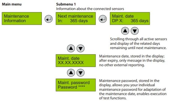 5.6 Display Parameter
In the menu Display Parameter you can find the general, security irrelevant parameters of the gas controller.
These parameters can be changed during the operation mode of the controller. 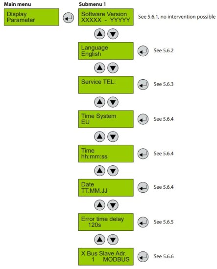 5.6.1 Software Version
| Symbol | Description | Function |
| XXXXX YYYYY | Software Version of the displays Software Version of the basic board | XXXXX Software Version YYYYY Software Version |
5.6.2 Language
| Symbol | Description | Default | Function |
| English | Language | English | English USA English German French |
5.6.3 Service Phone Number
The service phone no. can be entered individually in the next menu.
| Symbol | Description | Default | Function |
| Phone No. | Input of the individual service phone no. |
5.6.4 System Time, System Date
Input and correction of time and date. Selection of time and date format
| Symbol | Description | Default | Function |
| EU | Time format | EU | EU = Display of time and date in EU format US = Display of time and date in US format |
| hh.mm.ss | Time | hh.mm.ss = Input of the correct time (EU format) hh.mm.ss pm = Input of the correct time (US format) | |
| TT.MM.JJ | Date | TT.MM.JJ = Input of the correct date (EU format) MM.TT.JJ = Input of the correct date (US format) |
5.6.5 Error Time Delay
| Symbol | Description | Default | Function |
| s | Delay | 120s | Definition of a delay time when a communication error is shown on the display. (A delay on the fault output is not allowed, therefore not used.) |
5.6.6 X Bus Slave Address
(only existing, if X Bus function is available)
| Symbol | Description | Default | Function |
| Address | Slave address at the X Bus interface | 1 | Input of the slave address at the X bus. In addition to the address, the available option appears. Currently only Modbus available (pay attention to the additional documentation of the protocol) |
5.7 Parameters
In the menu Parameters you can find the parameter functions of the gas controller.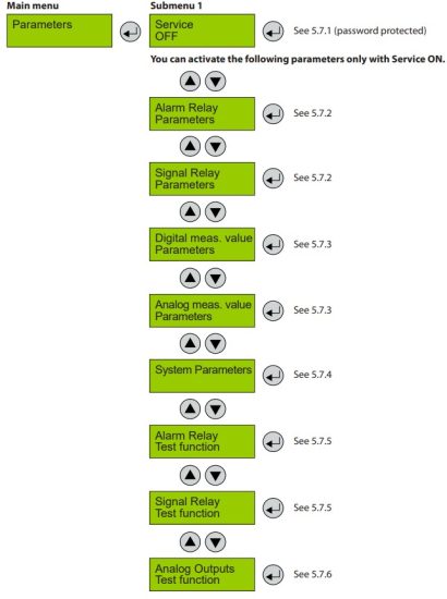
5.7.1 Display Parameter
Service and maintenance work mustn’t be executed when the gas controller is in the normal measuring mode for it isn’t sure that all response times and functions can be observed correctly.
For calibration and service work you first have to activate the special status mode on the controller. Only then you are allowed to change the safety related parameters. The special operating mode is activated by, among others, the function Service ON.
Further parameters menu items are therefore only accessible in the Service ON state. The Service ON state is reset to normal operation mode either automatically 15 minutes after the last key press or manually in the menu by the operator.
Sensors can’t be switched into the “special mode” from the controller. It can only be done directly at the sensor using the tool. Sensors in the “special mode” are not included in the alarm evaluation.
| Symbol | Description | Default | Function |
| OFF | Service | OFF | OFF = No reading and changing of parameters. ON = Controller in Special status mode, parameters can be read and changed. |
5.7.2 Menu Relay Parameter
Reading and changing of the parameters separately for each relay.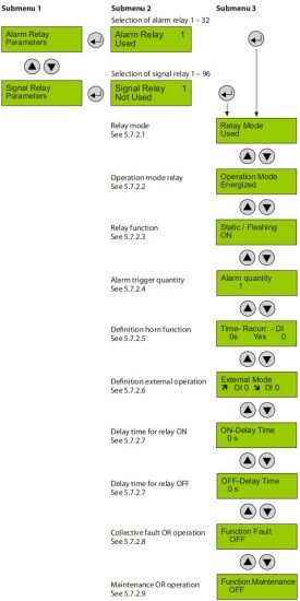 5.7.2.1 Relay Mode
Definition of the relay mode
| Symbol | Description | Default | Function |
| Used | Mode | Used | Used = Relay is registered on the controller and can be used Not Used = Relay is not registered on the controller |
5.7.2.2 Relay Operation Mode
Definition of the relay operation mode
The terms energized / de-energized for this item come from the terms open-circuit and closed-circuit principle used for safety circuits. Here, however, not the relay contact circuit is meant (as a changeover contact, optionally available in the two principles), but the activation of the relay coil.
The LEDs attached to the modules show the two states in analogy. (LED off -> relay de-energized)
| Symbol | Description | Default | Function |
| De-energ. | Mode | De-energ. | De-energ. = Relay (and LED) de-energized, if no alarm active Energized = Relay (and LED) permanently energized, if no alarm active |
5.7.2.3 Relay Function Static / Flash
Definition of the relay function
The function “Flashing” represents a connection option for warning devices to improve visibility. If “Flashing” is set, this mustn’t be used as a safe output circuit any more.
A combination of relay mode energized with flashing operation makes no sense and is therefore suppressed.
| Symbol | Description | Default | Function |
| ON | Function | ON | ON = Relay function flashing at alarm ( = time fixed 1 s) impulse / break = 1:1 OFF = Relay function static ON at alarm |
5.7.2.4 Alarm Trigger Quantity
In some applications it is necessary that the relay switches only at the nth alarm. Here you can set the number of alarms necessary for relay tripping.
| Symbol | Description | Default | Function |
| Quantity | Function | 1 | Only if this quantity is reached, the relay trips. |
5.7.2.5 Horn Function (not safe output circuit because resettable)
The horn function is considered active if at least one of the two parameters (time or assignment to digital input) is set. The horn function retains its functionality even for alarms in latching mode.
| Symbol | Description | Default | Function |
| Recurrence | Reset mode | 0 | 0 = Reset of the relay after time having run out via DI (external) or by pushbuttons 1 = After reset of the relay, time starts. At the end of the set time, the relay is activated again (recurrence function). |
| Time | 120 | Enter time for automatic reset function or recurrence function in s 0 = no reset function |
|
| DI | 0 | Assignment, which digital input resets the relay. |
Horn function resettable:
The activated horn can be permanently reset with this function.
The following possibilities to acknowledge are available for the alarm relay as horn relay:
- By pressing the left button (ESC). Only available in starting menu.
- Automatic reset at the end of the preset time (active, if value > 0).
- By an external pushbutton (assignment of the appropriate digital input DI: 1-n).
Due to fixed polling cycles, external buttons must be pressed for a few seconds before the reaction occurs.
After successful acknowledgment the horn remains permanently reset until all assigned alarms for this relay function are inactive again.
Only then it is triggered anew in case of an alarm.
Acknowledge the horn relay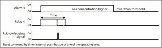 5.7.2.5 Horn Function (not safe output circuit because resettable) (Continued)
Recurrence of the horn relay
After an alarm has been triggered, the horn will remain active until a reset action is done. After acknowledgment of the horn relay/s (clicking a button or via external input) a timer starts. When this time has run out and the alarm is still acting, the relay is set again.
This process is repeated endlessly as long as the associated alarm remains active.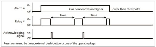 5.7.2.6 External Override of Alarm / Signal Relay via DI
Manual operation of the alarm relays via DI does not trigger the “special mode”, as this is a deliberate and configured functionality. The use of the override should be used with caution, particularly the function of setting “external OFF”.
Assignment of a digital input (DI) for the external switching on and off of the alarm relay.
This function has priority to gas alarm.
If External ON and External OFF are configured simultaneously to the same relay and both are active at the same time, so in this state, only the External OFF command is executed.
In this mode, too, the relays work respecting the parameter settings “Static / Flash” and “energized / de-energized”.
| Symbol | Description | Default | Function |
| ↗ DI 0 | External ON | 0 | As long as DI 1-X is closed, relay switches ON |
| ↘ DI 0 | External OFF | 0 | As long as DI 1- X is closed, relay switches OFF. |
5.7.2.7 External Override of Alarm / Signal Relay via DI
Definition of the switch-on and switch-off delay of the relays.
If the latching mode is set for this relay, the respective switch-off delay is without effect.
| Symbol | Description | Default | Function |
| 0 s | Switch-ON Delay Time | 0 | Alarm / Signal Relay is only activated at the end of the defined time. 0 sec. = No delay |
| 0 s | Switch-OFF Delay Time | 0 | Alarm / Signal Relay is only deactivated at the end of the defined time. 0 sec. = No delay |
5.7.2.8 OR Operation of Fault to Alarm / Signal Relay
Enables or disables the Fault OR operation of the current alarm / signal relay.
If the OR operation for this relay is set to active = 1, all device faults will activate the output in addition to the alarm signals.
In practice, this ORing will be used if, for example, fans should run or warning lights should be activated in case of device malfunction, since the fault message of the central control is not permanently monitored.
Note:
Exceptions are all errors of the measurement point because the MPs can be assigned to each alarm separately in the menu MP Parameters. This exception is used to build up targeted zone related signaling in case of MP errors, which should not affect other zones.
| Symbol | Description | Default | Function |
| 0 | No assignment | 0 | Alarm and/or signal relay isn’t affected if a device fault occurs. |
| 1 | Activated assignment | 0 | Alarm and/or signal relay turns on if a device fault occurs. |
5.7.2.9 OR Operation of Maintenance to Alarm / Signal Relay
Enables or disables the Maintenance OR operation of the current alarm / signal relay.
If the OR operation for this relay is set to active = 1, the output will be activated in addition to the alarm signals when at least one maintenance message is pending.
In practice, this ORing will be used if, for example, fans should run when the sensor accuracy isn’t ensured anymore because of missing calibration (therefore pending maintenance message) or warning lights should be activated, since the maintenance information of the central control is not permanently monitored.
Note:
Resetting of the activated maintenance message is only possible by calibration of the sensors or by disabling this OR function.
| Symbol | Description | Default | Function |
| 0 | No assignment | 0 | Alarm and/or signal relay isn’t affected if a maintenance message occurs. |
| 1 | Activated assignment | 0 | Alarm and/or signal relay turns on if a maintenance message occurs. |
5.7.3 Menu MP Parameters
For reading and changing measuring point parameters for each bus and analog sensor including registration of MP and assignment of the alarm relays. 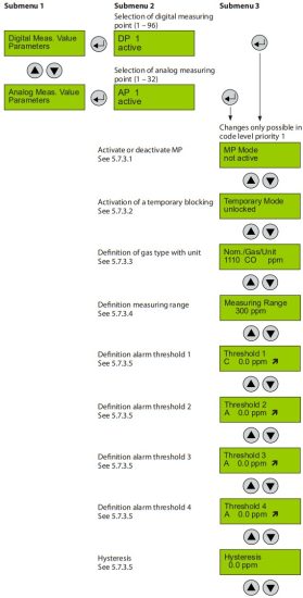
 5.7.3.1 Activate – Deactivate MP
Deactivation shuts the registered / not registered sensor down in its function, which means that there is no alarm or fault message at this measurement point. Existing alarms and faults are cleared with deactivation. Deactivated sensors do not output a collective fault message.
| Symbol | Description | Default | Function |
| active | MP Mode | Not active | active = Measuring point activated at the controller. not active = Measuring point not activated at the controller. |
5.7.3.2 Lock or Unlock MP
In the temporary Lock Mode, the function of the registered sensors is put out of service, which means that there is no alarm or fault message at this measuring point. Existing alarms and faults are cleared with the locking. If at least one sensor is blocked in its functionality, the collective fault message is activated after expiry of the internal fault delay time, the yellow fault LED is flashing and a message appears in the menu System Errors.
| Symbol | Description | Default | Function |
| unlocked | Lock mode | unlocked | unlocked = MP free, normal operation locked = MP locked, SSM (collective fault message) active |
5.7.3.3 Selection Gas Type with Unit
Selection of the desired and connected gas sensor type (connection possible as digital sensor cartridge Basic, Premium or Heavy Duty).
The selection contains all necessary information for the controller, and is also used for comparing the real, digital data with the settings.
This feature increases the user and operating security.
There is an entry available per gas type for each unit.
| Sensor | Internal type | Measuring range | Unit |
| Ammonia EC 100 | E1125-A | 0-100 | ppm |
| Ammonia EC 300 | E1125-B | 0-300 | ppm |
| Ammonia EC 1000 | E1125-D | 0-1000 | ppm |
| Ammonia SC 1000 | S2125-C | 0-1000 | ppm |
| Ammonia EC 5000 | E1125-E | 0-5000 | ppm |
| Ammonia SC 10000 | S2125-F | 0-10000 | ppm |
| Ammonia P LEL | P3408-A | 0-100 | % LEL |
| CO2 IR 20000 | I1164-C | 0-2 | % Vol |
| CO2 IR 50000 | I1164-B | 0-5 | % Vol |
| HCFC R123 SC 2000 | S2064-01-A | 0-2000 | ppm |
| HFC R404A, R507 SC 2000 | S2080 | 0-2000 | ppm |
| HFC R134a SC 2000 | S2077 | 0-2000 | ppm |
| HC R290 / Propane P 5000 | P3480-A | 0-5000 | ppm |
5.7.3.4 Measuring Range Definition
The measurement range must be adapted to the working range of the connected gas sensor.
For additional control by the installer, the settings in the controller must mandatorily match with the used sensors. If the types of gas and/or measurement ranges of the sensor don’t agree with the settings of the controller, the error “EEPROM / configuration error” is generated, and the collective fault message is activated.
The range also affects the display of the measured values, alarm thresholds and hysteresis. For measuring ranges <10 three decimals places, <100 two decimal places, <1000 one decimal place are displayed. For measuring ranges => 1000, the display is without decimal place. The resolution and accuracy of the calculation is not affected by the different measuring ranges.
5.7.3.5 Threshold / Hysteresis
For each measuring point four alarm thresholds are available for free definition. If the gas concentration is higher than the set alarm threshold, the associated alarm is activated. If the gas concentration falls below the alarm threshold inclusive hysteresis the alarm is again reset.
In the mode “Alarm at falling” the corresponding alarm is set in case of falling below the set alarm threshold and reset again when exceeding the threshold plus hysteresis. The display depends on the set measuring range: see 4.8.3.4. Unused alarm thresholds have to be defined at measuring range end point, in order to avoid undesired alarms. Higher-level alarms automatically activate the lower-level alarms.
| Symbol | Description | Default | Function | Symbol |
| A | Evaluation | A | A C | A = Alarm evaluation with average value of MP C = Alarm evaluation with current value of MP |
| 80 ppm | Alarm threshold | 40 80 100 120 15 |
Threshold 1 Threshold 2 Threshold 3 Threshold 4 Hysteresis |
Gas concentration > Threshold 1 = Alarm 1 Gas concentration > Threshold 2 = Alarm 2 Gas concentration > Threshold 3 = Alarm 3 Gas concentration > Threshold 4 = Alarm 4 Gas concentration < (Threshold X –Hysteresis) = Alarm X OFF |
| ↗ | ↗ | ↗ = Alarm release at increasing concentrations ↘ = Alarm release at falling concentrations |
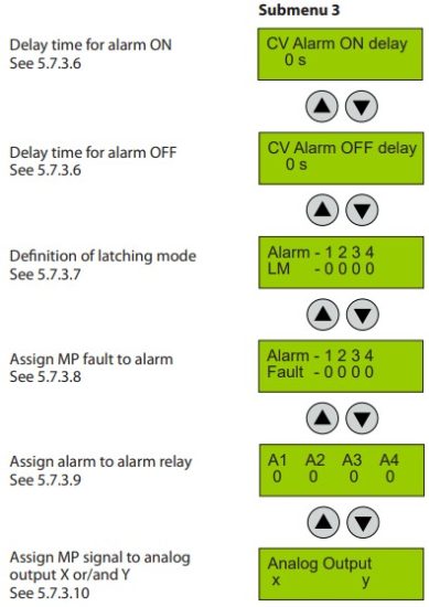
5.7.3.6 Delay for Alarm ON and/or OFF for Current Value Evaluation
Definition of delay time for alarm ON and/or alarm OFF. The delay applies to all alarms of an MP, not with average value overlay, see 5.7.3.7.
| Symbol | Description | Default | Function |
| 0 s | CV Alarm ON delay | 0 | Gas concentration > Threshold: Alarm is only activated at the end of the fixed time (sec.). 0 sec. = No delay |
| 0 s | CV Alarm OFF delay | 0 | Gas concentration < Threshold: Alarm is only deactivated at the end of the fixed time (sec.). 0 sec. = No delay |
5.7.3.7 Latching Mode Assigned to Alarm
In this menu you can define, which alarms should work in latching mode.
| Symbol | Description | Default | Function |
| Alarm – 1 2 3 4 SBH – 0 0 0 0 |
Latching MP | 0 0 0 0 | 0 = No latching 1 = Latching |
5.7.3.8 MP Fault Assigned to Alarm
In this menu you can define, which alarms should be activated by a fault at the measuring point.
| Symbol | Description | Default | Function |
| Alarm – 1 2 3 4 SBH – 0 0 0 0 |
Fault MP | 1 1 0 0 | 0 = Alarm not ON at MP fault 1 = Alarm ON at MP fault |
5.7.3.9
Alarm Assigned to Alarm Relay
Each of the four alarms can be assigned to any physically existing alarm relay 1 to 32 or signal relay R1 to R96. Unused alarms aren’t assigned to an alarm relay.
| Symbol | Description | Default | Function |
| 0 | A1 A2 A3 A4 | 0 0 0 0 |
RX = Assignment of the alarms A1 – A4 to the signal relays R1-R96 X = Assignment of the alarms A1 – A4 to the alarm relays 1-32 |
5.7.3.10 MP Signal Assigned to Analog Output
The measuring point signal (current or average value) can be assigned to one of the max. 16 analog outputs. The same assignment to different outputs (8) generates a functional duplication. This is often used to control remote devices in parallel (supply fan in the basement, exhaust fans on the roof).
If several assignments are made to one analog output, the output signal is output WITHOUT fault information. It should be noted that a mixture of different types of gas often makes no sense. In the case of a single assignment = additional analog output 1:1, the signal is output WITH fault information.
Analog output see also: 5.7.4.4.
| Symbol | Description | Default | Function |
| x y | Analog Output | x y | x = MP Signal is assigned to analog outputx (activates output control -> signal can be used) y = MP Signal is assigned to analog outputy (activates output control -> signal can be used) 0 = MP Signal isn’t assigned to any analog output or no release in the System Parameters (no active output control) |
5.7.4 Menu System Parameters
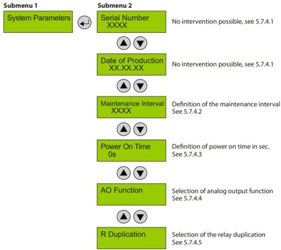 5.7.4.1 System Information
| Symbol | Description | Default | Function |
| XXXX | Serial Number | 0 | Serial number |
| XX.XX.XX | Date of Production | 0 | Date of production |
5.7.4.2 Maintenance Interval
The description of the maintenance concept is shown in 4.5.
The maintenance interval of the controller is set here. If 0 is set, this function is disabled.
| Symbol | Description | Default | Function |
| XXXX | Maintenance Interval | Entry of the interval between two services in days |
5.7.4.3 Power On Time
Gas sensors need a running-in period, until the chemical process of the sensor reaches stable conditions. During this running-in period the current signal can lead to an unwanted triggering of a pseudo alarm. Therefore the Power On time is started at the Gas Controller after you have switched on the power supply. While this time is running out, the Gas Controller doesn’t activate alarms or UPS relays. The Power On status occurs on the first line of the starting menu.
Attention:
During the Power On phase the controller is in “Special Mode” and doesn’t perform further functions beside the starting diagnostic procedures. A count-down Power On time in seconds is shown on the display.
| Symbol | Description | Default | Function |
| 30s | Power On time | 30s | XXX = Definition of the power On time (sec.) |
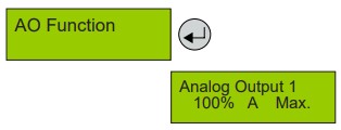
5.7.4.4 Analog Output
The Gas Controller Module as well as the expansion modules 1 to 7 have got two analog outputs (AO) with 4 to 20 mA signal each. The signal of one or more measuring points can be assigned to each of the analog outputs; in this case, the signal control becomes active and the output is current monitored. The signal monitoring is self-healing and therefore mustn’t be acknowledged. The assignment is done in the menu “MP Parameter” for each MP. The measuring point sends the current value signal to the analog output.
Out of the signals of all assigned measuring points the Gas Controller determines the minimum, the maximum or the average value and transmits it to the analog output. The definition, which value is transmitted, is done in the menu “Analog Output X”.
To allow flexible air volume regulation of speed-controlled motors, the slope of the output signal can be adapted to the on-site conditions and varied between 10 – 100%.
As an alternative to the activation via the controller (defined by the number 1), the analog inputs can be assigned to the analog outputs of the same expansion module (menu in the expansion module).
For this purpose, the number 10 – 100% has to be entered on the expansion module.
| Symbol | Description | Default | Function |
| Analog Output 1 | Selection of channel | Selection of the analog output 1-16 | |
| 0 1 10-100 % |
Selection of output signal | 100 % | 0 = Analog output is not used (therefore always de-activated response monitoring) 1 = Local use (not used in the central control) Selection of signal slope- permitted range 10 – 100 % 100 % gas signal control = 20 mA 10 % gas signal control = 20 mA (high sensitivity) |
| A | Selection of source | A | C = Source is current value A = Source is average value CF = Source is current value and additional fault message at AO AF = Source is average value and additional fault message at AO |
| Max. | Selection of output mode | Max. | Min. = Displays the minimum value of all assigned MP Max. = Displays the maximum value of all assigned MP Average = Displays the average value of all assigned MP |
 5.7.4.5 Relay Multiplication
With the relay multiplication table, it is possible in the controller system to assign additional relay functions to an alarm. This corresponds in the end to one multiplication of the source alarm situation per entry.
The additional relay follows the alarm status of the source, but uses its own relay parameters to allow different needs of the doubled relay. So the source relay can be configured, for example, as safety function in de-energized mode, but the doubled relay can be declared with flashing function or as horn function.
There is a maximum of 20 entries for IN relays and OUT relays. Thus it is possible, for example, to expand one relay to 19 others or to double max. 20 relays.
In the column IN (source), you can set the relay assigned to an alarm in the menu MP Parameter.
In the column OUT (target), you can enter the relay needed in addition.
Note:
Manual intervention in the menu Relay Status or override in external ON or OFF by external DI do not count as alarm status, so they do only affect the IN relay. If this is also desired for the OUT relay, it has to be configured separately for each OUT relay.
| Number | Description | Default Status | Function |
| 0-30 0-96 |
IN AR Relay IN SR Relay | 0 | 0 = Function off X = Relay X should be multiplied (information source). |
| 0-30 0-96 |
OUT AR Relay OUT SR Relay | 0 | 0 = Function off X = Relay X (target) should switch together with IN relay. |
Example 1:
3 relay contacts are needed with the same effect of relay 3, (see assignment of the relays in chapter MP
Parameters.)
Entry: 1: IN AR3 OUT AR7
Entry: 2: IN AR3 OUT AR8
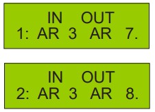 If relay 3 is activated via an alarm, relays AR3, AR7 and AR8 switch at the same time.
Example 2:
2 relay contacts each are needed from 3 relays (for ex. AR7, AR8, AR9).
Entry: 1: IN AR7 OUT AR12 (Relay 12 switches at the same time with relay 7)
Entry: 2: IN AR8 OUT AR13 (Relay 13 switches at the same time with relay 8)
Entry: 3: IN AR9 OUT AR14 (Relay 14 switches at the same time with relay 9)
This means that relay AR7 switches with AR12;
AR8 with AR13; AR9 with AR14.
The two examples can be mixed up, too. 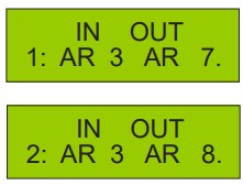
5.7.5 Test Function of the Alarm and Signal Relays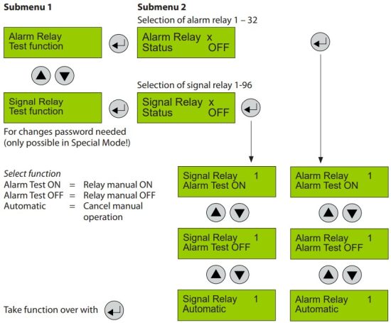 The test function sets the target device (selected relay) in Special Mode and activates a timer that reestablishes the normal measurement mode after 15 minutes and ends the test function.
Therefore the yellow LED on the controller is on in the manual ON or OFF status.
The external operation of the relays via an assigned digital input has priority to the manual test function in this menu item.
| Symbol | Description | Default | Function |
| AR Status | Relay Nr. X | X = 1 – 32 Select alarm relay | |
| SR Status | Relay Nr. X | X = 1 – 96 Select signal relay | |
| OFF | Relay Status | OFF | Status OFF = Relay OFF (no gas alarm) Status ON = Relay ON (gas alarm) Manual OFF = Relay manual OFF Manual ON = Relay manual ON Automatic = Relay in automatic mode |
5.7.6 Test Function of the Analog Outputs
This feature is only available in Special Mode.
With the test function you can enter the value (in mA) that should be physically output.
The test function via the controller can only be applied when the analog outputs are overridden (configuration 1 of analog outputs in the system parameters of the associated device, see 5.7.4.4).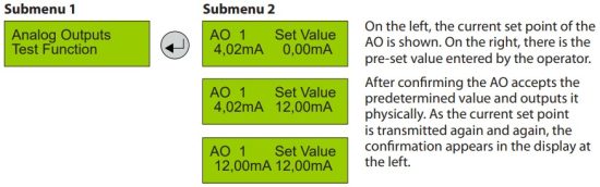 Any information, including, but not limited to information on selection of product, its application or use, product design, weight, dimensions, capacity or a or any other technical data in product manuals, catalogues descriptions, advertisements, etc. and whether made available in writing, orally, electronically, online or via download, shall be considered informative, and is only binding if and to the extent, explicit reference is made in a quotation or order confirmation. Danfoss cannot accept any responsibility for possible errors in catalogues, brochures, videos and other material.
Danfoss reserves the right to alter its products without notice. This also applies to products ordered but not delivered provided that such alterations can be be made without changes to form, fit or function of the product.
All trademarks in this material are property of Danfoss A/S or Danfoss group companies. Danfoss and the Danfoss logo are trademarks of Danfoss A/S. All rights reserved.
![]() BC272555441546en-000201
BC272555441546en-000201
© Danfoss | CLimate Solutions | 2022.03
Documents / Resources
 |
Danfoss Gas Detection Controller Unit and Expansion Module [pdf] User Guide BC272555441546en-000201, Gas Detection Controller Unit and Expansion Module, Controller Unit and Expansion Module, Expansion Module |