![]() APT-VERTI-1
APT-VERTI-1
Communication module
User Manual
APT-VERTI-1 Communication Module Adaptor
APPLICATION
The APT-VERTI-1 communication module is an RF intermediate transmission device between the RF data output meter modules and the meter-reading collector’s app installed on a mobile device. The primary function of the communication module is to onvert the data signals between an RF interface operating in the ISM 868 MHz band and a Bluetooth/USB interface.
When coupled with the meter-reading collector’s app, the communication module can:
- receive RF data frames in areas of high RF meter output traffic.
- reconfigure meter RF module profile settings.
Table of APT-VERTI-1 communication module compatibility with Apator Powogaz RF modules
| Device name | Meter name | Supported operating modes | |
| Readout (T1) | Configuration (installation & servicing: T2) | ||
| APT-WMBUS-NA-1 | All AP water meters with universal module preequipped counters | x | x |
| AT-WMBUS-16-2 | JS1,6 to 4-02 smart | x | x |
| AT-WMBUS-19 | JS6,3 to 16 master | x | x |
| APT-03A-1 | JS1,6 to 4-02 smart | x | x |
| APT-03A-2 | SV-RTK 2,5 to SV-RTK 16 | x | x |
| APT-03A-3 | JS6,3 to 16 master | x | x |
| APT-03A-4 | MWN40 to 300 | x | x |
| APT-03A-5 | MWN40 to 300 IP68 | x | x |
| APT-03A-6 | JS1,6 to 4-02 smart, Metra version | x | x |
| AT-WMBUS-17 | SV-RTK 2,5 to SV-RTK 16 | x | x |
| AT-WMBUS-18-AH | MWN40 to 125 IP68 | x | x |
| AT-WMBUS-18-BH | MWN150 to 300 IP68 | x | x |
| AT-WMBUS-01 | Legacy water meter versions | x | _ |
| AT-WMBUS-04 | All AP water meters with NK transmitters or water meters pre-equipped for an AT- WMBUS-NE pulse module | x | — |
| AT-WMBUS-07 | Legacy water meter versions | x | — |
| AT-WMBUS-08 | JS1,6 to 4-02 smart | x | — |
| AT-WMBUS-09 | MWN40 to 125 | x | — |
| AT-WMBUS-10 | MWN150 to 300 | x | — |
| AT-WMBUS-11 | JS3,5 to 10; MP40 to 100; JS50 to 100 | x | — |
| AT-WMBUS-11-2 | JS6,3 to 16 master | x | — |
| AT-WMBUS-Mr-01 | Elf compact heat meter | x | — |
| AT-WMBUS-Mr-01Z | Elf compact heat meter | x | — |
| AT-WMBUS-Mr-02 | LQM | x | |
| AT-WMBUS-Mr-02Z | LQM | x | |
| AT-WMBUS-Mr-10 | Faun calculator | x | — |
| E-ITN-30-5 | Geat cost allocator | x | — |
| E-ITN-30-51 | Geat cost allocator | x | — |
| E-ITN-30-6 | Geat cost allocator | x | — |
| Ultrimis | Ultrasonic Water Meter | x | — |
| AT-WMBUS-05-1 | Retransmitter | x | — |
| AT-WMBUS-05-2 | Retransmitter | x | — |
| AT-WMBUS-05-3 | Retransmitter | x | — |
| AT-WMBUS-05-4 | Retransmitter | x | — |
The APT-VERTI-1 enhances the success rate of RF communication data frame reading. This mode of operation gives up to a 10% improvement in conflicting data frame recovery (depending on the network traffic intensity).
REGULATORY AND STANDARD COMPLIANCE
Apator Powogaz S.A. hereby declares that this product meets the requirements of the following reference regulations and standards:
- 2014/53/EU Radio Equipment Directive (RED)
- 2011/65/EU RoHS
- PN-EN 13757 – Communication systems for meters and remote reading of meters. Parts 1-4
- Supports Wireless M-Bus
- This device has received the mark
- Cooperates with devices working in OMS standard
DEVICE OVERVIEW
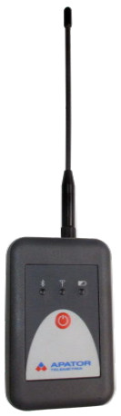
The communication module comprises an electronic system and a power supply battery, both housed in a plastic enclosure. The communication module features the following data interfaces: Mini USB and an RPSMA-compliant RF antenna; the communication
module also features three LED indicators and an On/Off/Bluetooth selector button.The communication module works only with the RF antenna connected.
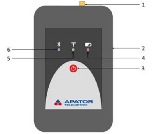
3.1. Device components
 |
|
| 1 | RP-SMA RF antenna port |
| 2 | Mini USB-A port |
| 3 | On/Off/Bluetooth selector button |
| 4 | Power LED |
| 5 | Rx LED |
| 6 | Bluetooth Connected LED |
3.2. Device and standard accessory RF antenna dimensions
Physical characteristics

3.3. Specification
| Wireless M-Bus | |||
| T1 mode | 868.950 MHz | ||
| T2 mode | 868.300 MHz | ||
| Transmitter power output | 14 dBm (25 mW) | ||
| Receiver sensitivity | -110 dBm | ||
| Bluetooth | |||
| Transmitter power output | 4 dBm (2.5 mW) | ||
| Range | max 10 m | ||
| Profile | Serial port | ||
| Class | 2 | ||
| Power supply and operation | |||
| Battery path | Li-ion | ||
| Battery support time at full charge | 24 h | ||
| Battery charging time | 6 h | ||
| Automatic power-off | |||
| Minimum battery declared capacity life | 2 years max. | ||
| Ambient temperature | |||
| Operating temperature range | 0°C to 55°C | ||
| Data Interfaces | |||
| RP-SMA | 868 MHz RF antenna connector | ||
| Mini USB A | PC data communication & battery charging | ||
| Weight | |||
| 130 g | |||
| Ingress protection rating | |||
| IP30 | |||
DEVICE OPERATION
4.1. First steps
 To begin using the communication module, first switch it on.
Press and hold the On/Off/Bluetooth selector button (3) for 1 second to do this. The communication module will be on after all three LEDs blink once.
4.2. Communication module powered on The RF receiver is active when the green LED (5) is on. Each RF data frame successfully received via Wireless M-Bus is indicated by the same LED switching off for a brief moment.
4.3. Battery level
 The battery level is indicated by the red LED (4) and directly proportional to the red LED light time in 1-second long cycles.
4.4. Bluetooth interface
 Connecting a mobile terminal to the communication module requires a standard Bluetooth pairing procedure:
- Keep the Bluetooth-enabled mobile terminal within 10 m of the APT-VERTI-1 communication module.
- Switch on the APT-VERTI-1 Bluetooth interface. Briefly depress the On/Off/Bluetooth selector button (3). The blue LED (6) will flash when the Bluetooth interface is on.
- Operate the mobile terminal menu to pair the device with the communication module. If unable to pair, see the mobile terminal operating manual. The default Bluetooth PIN is “0000”.
The blue LED (6) will stay on steadily when the mobile terminal is paired with the communication module.
4.5. Power saver mode
 The communication module features a power saver mode. If left on without the Bluetooth interface paired and/or the USB port connected to an external device, the communication module powers off automatically.
The time to automatic power off is 15 minutes.
4.6. Battery charging and maintenance Due to the performance characteristics of lithium-ion battery packs, avoid leaving the APT-VERTI-1 communication module with the battery drained for too long. Otherwise, the battery service life will be reduced. The battery is deeply discharged when the red LED (4) blinks briefly every 10 seconds. The communication module cannot be powered on when this happens.
![]() Recharge the battery by connecting the APTVERTI-1 communication module to ether of the following:
Recharge the battery by connecting the APTVERTI-1 communication module to ether of the following:
- a USB port of a PC;
- a USB car charger;
- a mains outlet via an USB power adapter.
The power source must output 5 V with a minimum charging current of 500 mA.
The battery recharging time from a deep discharge is up to 6 hours.
Caution: Use the battery strictly as specified here to enjoy its maximum service life. The battery can only be replaced by an authorized service centre of the manufacturer.
OPERATING PRECAUTIONS
![]() Protect the product against shocks and damage during transport.
Protect the product against shocks and damage during transport.
Store between 0°C and 25°C.
Verify that the battery has been fully charged before operating the product.
Switch on the product before use.
Switch off the product when not in use.
Operate the product at ambient temperatures and the conditions specified in this User Manual.
![]() Do not dispose of with regular waste/trash. Return the product to a WEEE collection point for disposal. Help protect the natural environment.
Do not dispose of with regular waste/trash. Return the product to a WEEE collection point for disposal. Help protect the natural environment.
WARRANTY TERMS AND CONDITIONS
The manufacturer guarantees proper performance of the communication module for the duration specified in § 2 of the Apator-Powogaz General Warranty Terms & Conditions only if the conditions for transport, storage and operation are followed.
Apator Powogaz S.A. has the right to modify and improve the products without notice
![]() Apator Powogaz S.A.
Apator Powogaz S.A.
ul. Klemensa Janickiego 23/25, 60-542 Poznań
tel. +48 (61) 84 18 101
e-mail sekretariat.powogaz@apator.com
www.apator.com
2021.035.I.EN
Documents / Resources
 |
Apator APT-VERTI-1 Communication Module Adaptor [pdf] User Manual APT-VERTI-1 Communication Module Adaptor, APT-VERTI-1, Communication Module Adaptor, Module Adaptor, Adaptor |