intel UG-20093 ModelSim FPGA Edition Simulation

ModelSim* – Intel® FPGA Edition Simulation Quick-Start Intel® Quartus® Prime Pro Edition
This document demonstrates how to simulate an Intel® Quartus® Prime Pro Edition design in the ModelSim* – Intel FPGA Edition simulator. Design simulation verifies your design before device programming. The Intel Quartus Prime software generates simulation files for supported EDA simulators during design compilation.
Figure 1. ModelSim – Intel FPGA Edition
Design simulation involves generating simulation files, compiling simulation models, running the simulation, and viewing the results. The following steps describe this flow:
- Open the Example Design on page 4
- Specify EDA Tool Settings on page 4
- Generate a Simulator Setup Script Template on page 5
- Modify the Simulator Setup Script on page 6
- Compile and Simulate the Design on page 8
- View Signal Waveforms on page 9
- Add Signals to the Simulation on page 11
- Rerun Simulation on page 12
- Modify the Simulation Testbench on page 12
Open the Example Design
The PLL_RAM example design includes Intel FPGA IP cores to demonstrate the basic simulation flow. Download the example design files and open the project in the Intel Quartus Prime software.
Note: This Quick-Start requires a basic understanding of hardware description language syntax and the Intel Quartus Prime design flow, as the Intel Quartus Prime Pro Edition Foundation Online Training describes.
- Download and unzip the Quartus_Pro_PLL_RAM.zip design example.
- Launch the Intel Quartus Prime Pro Edition software version 19.4 or later.
- To open the example design project, click File ➤ Open Project, select the pll_ram.qpf project file, and then click OK.
Figure 2. pll_ram Project in the Intel Quartus Prime Pro Edition
Specify EDA Tool Settings
Specify EDA tool settings to generate simulation files for supported simulators.
- In the Intel Quartus Prime software, click Assignments ➤ Settings ➤ EDA Tool Settings.
- Under Simulation, select ModelSim-Intel FPGA as the Tool name. Retain the default settings for Format for output netlist and Output directory.

Generate a Simulator Setup Script Template
Simulator setup scripts help you to simulate the IP cores in your design. Follow these steps to generate the vendor-specific simulator setup script template for the IP modules in the example design. You can then customize this template for your specific simulation goals.
- To compile the design, click Processing ➤ Start Compilation. The Messages window indicates when compilation is complete.
- Click Tools ➤ Generate Simulator Setup Script for IP. Retain the default Output directory and Use relative paths whenever possible setting for the setup script file. The setup script template generates in the directory that you specify.
Figure 3. Generate Simulator Setup Scripts IP Dialog Box
Modify the Simulator Setup Script
Modify the generated simulator setup script to enable specific commands that simulate the IP cores in the project.
- In a text editor, open the /PLL_RAM/mentor/msim_setup.tcl file.
- Create a new text file with the name mentor_example.do and save it in the /PLL_RAM/mentor/ directory.
- In the msim_setup.tcl file, copy the section of code enclosed within the TOP-LEVEL TEMPLATE – BEGIN and TOP-LEVEL TEMPLATE – END comments, and then paste this code into the new mentor_example.do file.
- In the mentor_example.do file, delete the single pound (#) characters preceding the following highlighted lines to enable compilation commands:
Figure 4. Uncomment Highlighted Simulation Commands in the Script
- Replace the following lines in the mentor_example.do script:
Table 1. Specify Values in the mentor_example.do Script
| Replace this Line | With this Line |
| set QSYS_SIMDIR
<script generation output directory> |
../ |
| vlog <compilation options> <design and testbench files> |
vlog -vlog01compat -work work ../PLL_RAM.v vlog -vlog01compat -work work ../UP_COUNTER_IP/UP_COUNTER_IP.v vlog -vlog01compat -work work ../DOWN_COUNTER_IP/DOWN_COUNTER_IP.v vlog -vlog01compat -work work ../ClockPLL/ClockPLL.v vlog -vlog01compat -work work ../RAMhub/RAMhub.v vlog -vlog01compat -work work ../testbench_1.v |
| set TOP_LEVEL_NAME
<simulation top> |
set TOP_LEVEL_NAME tb |
| run -a |
add wave * view structure view signals run -all |
- Save the /PLL_RAM/mentor/mentor_example.do file. The following figure shows the mentor_example.do file after revisions are complete:
Figure 5. Completed Top-Level IP Simulation Setup Script
Compile and Simulate the Design
Run the top-level mentor_example.do script in the ModelSim – Intel FPGA Edition software to compile and simulate your design.
- Launch the ModelSim – Intel FPGA Edition software. The ModelSim – Intel FPGA Edition GUI organizes the elements of your simulation into separate windows and tabs.
- From PLL_RAM project directory, open the testbench_1.v file. Similarly, open the mentor/mentor_example.do file.
- To display the Transcript window, click View ➤ Transcript. You can enter commands for ModelSim – Intel FPGA Edition directly in the Transcript window.
- Type the following command in the Transcript window and then press Enter: do mentor_example.do
The design compiles and simulates, according to your specifications in the mentor_example.no script. The following figure shows the ModelSim – Intel FPGA Edition simulator:
Figure 6. ModelSim – Intel FPGA Edition GUI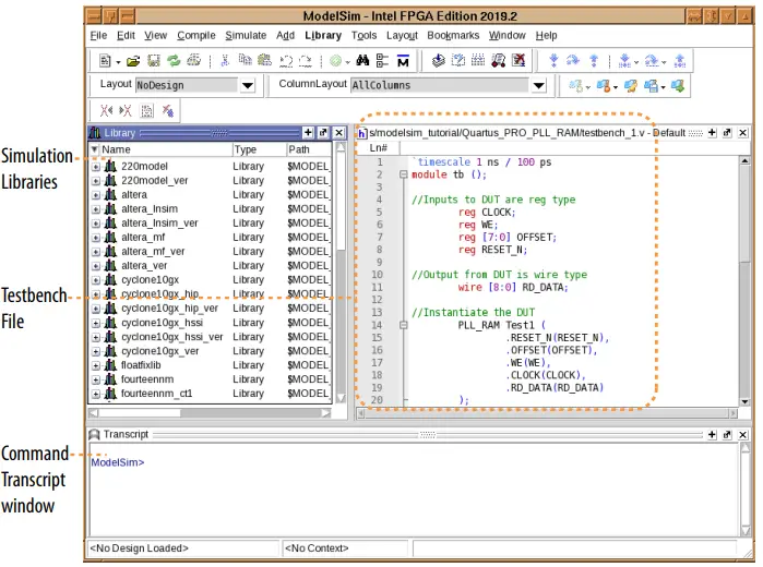
View Signal Waveforms
Follow these steps to view signals in the testbench_1.v simulation waveform:
- Click the Wave window. The simulation waveform ends at 11030 ns, as the testbench specifies. The Wave window lists the CLOCK, WE, OFFSET, RESET_N, and RD_DATA signals.
Figure 7. ModelSim – Intel FPGA Edition Wave Window
- To view the signals in the top-level pll_ram.v design, click the Sim tab. The Sim window synchronizes with the Objects window.
Figure 8. ModelSim – Intel FPGA Edition Sim and Objects Windows
- To view the top-level module signals, expand the tb folder in the Objects tab. Similarly, expand the Test1 folder. The Objects window displays the UP_module, DOWN_module, PLL_module, and RAM_module signals.
- In the Sim window, click a module under Test1 to display the module’s signals in the Objects window.
- View the simulation library files in the Library window.
Figure 9. ModelSim – Intel FPGA Edition Library Window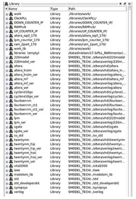
Add Signals to the Simulation
The CLOCK, WE, OFFSET, RESET_N, and RD_DATA signals automatically appear in the Wave window because the top-level design defines these I/O. In addition, you can optionally add internal signals to the simulation.
- In the Objects window, locate the UP_module, DOWN_module, PLL_module, and RAM_module modules.
- In the Objects window, select RAM_module. The module’s inputs and outputs are
- display.
Figure 10. Add Signals To Wave Window
- To add the internal signals between the down-counter and dual-port RAM module, right-click rdaddress and then click Add Wave.
- To add the internal signals between the up-counter and dual-port RAM module, right-click wraddress and then click Add Wave. Alternatively, you can drag and drop these signals from the Objects window to the Wave window.
- To generate the waveforms for the new signals you add, click Simulate ➤ Run ➤ Continue.
Rerun Simulation
You must rerun the simulation if you make changes to the simulation setup, such as adding signals to the Wave window, or modifying the testbench_1.v file. Follow these steps to rerun simulation:
- In the ModelSim – Intel FPGA Edition simulator, click Simulate ➤ Restart. Retain the default options and click OK. These options clear the waveforms and restart the simulation time, while retaining the necessary signals and settings.
Note: Alternatively, you can re-run the /PLL_RAM/mentor/mentor_example.do script to re-run simulation at the command line. - Click Simulate ➤ Run ➤ Run -all. The testbench_1.v file simulates according to the testbench specifications. To continue simulation, click Simulate ➤ Run ➤ Continue. This command continues the simulation until you click the Stop button.
Modify the Simulation Testbench
The testbench_1.v example testbench tests only a specific set of conditions and test cases. You can manually edit the testbench_1.v file in the ModelSim – Intel FPGA Edition simulator to test other cases and conditions:
- Open the testbench_1.v file in the ModelSim – Intel FPGA Edition simulator.
- Right-click in the testbench_1.v file to confirm that the file is not set to Read Only.
- Enter and save any additional testbench parameters in the testbench_1.v file.
- To generate the waveforms for a testbench that you modify, click Simulate ➤ Restart.
- Click Simulate ➤ Run ➤ Run -all.
ModelSim – Intel FPGA Edition Simulation Quick-Start Revision History
| Document Version | Intel Quartus Prime Version | Changes |
| 2019.12.30 | 19.4 | • Updated steps and screenshots for Intel Quartus Prime Pro Edition version 19.4.
• Updated design example file link and content. |
| 2018.09.25 | 18.0 | Corrected syntax errors in mentor_example.do Script. |
| 2018.05.07 | 18.0 | Removed unnecessary step from Run Simulation at Command Line
procedure. |
| 2017.07.15 | 17.1 | Initial release. |
Intel Corporation. All rights reserved. Intel, the Intel logo, and other Intel marks are trademarks of Intel Corporation or its subsidiaries. Intel warrants performance of its FPGA and semiconductor products to current specifications in accordance with Intel’s standard warranty, but reserves the right to make changes to any products and services at any time without notice. Intel assumes no responsibility or liability arising out of the application or use of any information, product, or service described herein except as expressly agreed to in writing by Intel. Intel customers are advised to obtain the latest version of device specifications before relying on any published information and before placing orders for products or services.
- Other names and brands may be claimed as the property of others.
Documents / Resources
 |
intel UG-20093 ModelSim FPGA Edition Simulation [pdf] User Guide UG-20093 ModelSim FPGA Edition Simulation, UG-20093, ModelSim FPGA Edition Simulation, FPGA Edition Simulation, Edition Simulation |


