Product Introduction
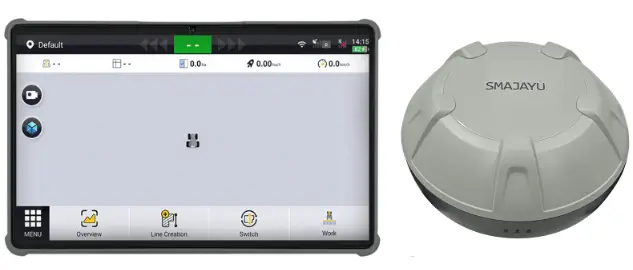
Agricultural Guidance System a kit that uses the PPP, SBAS, or RTK positioning technology to provide precise positioning and guidance for manual driving. By providing operation path planning and real-time navigation, Agricultural Guidance System helps agricultural machinery operators work with a higher accuracy. This system consists of a terminal, a GNSS receiver, and wiring harnesses. The terminal is installed with SMAJAYU · own navigation software.
Preparation Before Installation
Safety Instructions
Before installation, read the safety advice in this manual carefully to avoid doing harm to people and equipment.
Note that the following safety advice cannot cover all possible dangerous situations.
Installation
- Do not install the equipment in environments with high temperature, heavy dust, harmful gases, flammables, explosives, electromagnetic interference (for example, around large radar stations, transmitting stations, and substations). unstable voltages, great vibration, and strong noise.
- Do not install the equipment in places where water is likely to accumulate, seep, drip, and condense.
Disassembly
- After installation, do not frequently disassemble the equipment; otherwise, the equipment can be damaged.
- Before disassembly, turn off all power supplies and disconnect the cable from the battery to avoid equipment damage.
Electrical Operations
- Electrical operations must be performed by qualified personnel in accordance with local laws and regulations.
- Carefully check the working area for potential hazards, such as wet ground.
- Before installation, learn about the position of the emergency stop button. Use this button to cut off the power supply in case of accidents.
- Before cutting off the power supply, ensure that the equipment is turned off.
- Do not put the equipment in a humid place. Prevent liquids from entering the equipment.
- Keep it away from high power wireless equipment such as wireless transmitters, radar transmitters, high frequency and current devices, and microwave ovens.
- Direct or indirect contact with high voltage or utility power may cause death.
Requirements for Installation Site
To ensure the normal operation of the equipment and prolong its service life, the installation site must meet the following requirements.
Position
- Ensure that the installation position is firm enough to support the control terminal and accessories.
- Ensure that there is enough space to install the control terminal at the installation position, with some space set aside in every direction for heat dissipation.
Temperature and Humidity
- The temperature and humidity of the working environment should be kept within a reasonable range to ensure the normal operation and service life of the equipment.
- The equipment will be damaged if it works under improper environmental temperature and humidity.
- When the relative humidity is too high, insulating materials may not perform well, causing leakage currents. Mechanical property changes, rusting, and corrosion may also occur.
- When the relative humidity is too low, insulating materials will dry and contract, and static electricity may occur and damage the electric circuits of the equipment.
Air
Ensure that the contents of salt, acid, and sulfide in the air are within a reasonable range. Some hazardous substances will accelerate the rusting and corrosion of metals and the aging of parts. Keep the working environment free of harmful gases (for example, sulfur dioxide, hydrogen sulfide, nitrogen dioxide, and chlorine).
Power Supply
- Voltage input: The input voltage of Agricultural Guidance System should be in the range of 12 V to 24 V.
- Connect the power cable to the positive and negative electrodes correctly and avoid direct contact of the cable with hot objects.
Installation Tools
Prepare the following tools before installation.
| Agricultural Guidance System Installation Tools | ||||
| No. | Tool | Specifications | Qty. | Purpose |
| 1 | SIM card tray ejector | Install the SIM card. | ||
| 2 | Cross screwdriver | Medium | Install the GNSS receiver and bracket. | |
| 3 | Open-end wrench | 8 | Install the GNSS receiver bracket on the top of the machine. | |
| 4 | 11 | Fix the U-bolt on the base of the terminal. | ||
| 5 | 12/14 | Connect the battery cables. The bolt size depends on the vehicle model. | ||
| 6 Utility knife | I | Open the package. | ||
| 7 Scissors | I | Cut cable ties. | ||
| 8 | Tape measure | 5m | Measure the vehicle body. | |
Unpack and Check
Unpack and check the following items.
| Assembly | Name | Qty. | Remarks | |
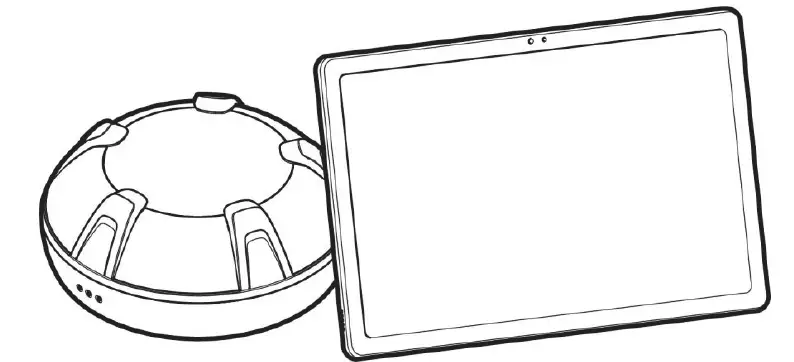
| 1 | Terminal | Terminal | ||
| 2 | Holder Bracket | |||
| 3 | Control Terminal Bracket | |||
| 4 | GNSS Receiver | GNSS Receiver | ||
| 5 | GNSS Receiver Bracket | Fix the GNS Sreceiver and bracket | ||
| 6 | 3M Sticker | 2 | ||
| 7 | Bolt M4xl2 | 4 | ||
| 8 | Tapping screw | 4 | ||
| 9 | Wiring Harness | Main Power Cable | ||
| 10 | GNSS Receiver Cable | |||
| 11 | Cab Charger Cable | |||
| 12 | Type C Cable | |||
| 13 | Charging Accessories | Cab Charger | ||
| 14 | Terminal Charger | l | ||
| 15 | Others | Nylon Cable Tie | 20 | |
| 16 | Waterproof Bag | 3 | ||
| 17 | User Manual | |||
| 18 | Certification | |||
| 19 | Warranty Card | |||
Note: The screws and U-bolts are shipped with the product and not listed here.
The items that you receive may differ. Check the items according to the packing list or purchase order. Contact the dealer if you have any question or if any item is missing.
Installation Instructions
Read Chapter 2 carefully and ensure that all requirements specified in Chapter 2 are met.
Check Before Installation
Before installation, make a detailed plan and arrangement regarding the installation position, power supply, and wiring of the equipment, and ensure that the installation site meets the following requirements.
- There is sufficient space to facilitate heat dissipation.
- The environmental temperature and humidity meet the requirements.
- The location meets the requirements for power supply and cabling.
- The selected power supply matches the system power.
- The location meets the requirements for normal working of the device.
- For user-specific equipment, ensure that the specific requirements are met.
Precautions for Installation
- Cut off the power supply when installing the device.
- Place the device in a well-ventilated environment.
- Do not place the device in a hot environment.
- Keep the device away from high-voltage cables.
- Keep the device away from strong thunderstorms and electric fields.
- Unplug the power supply before cleaning.
- Do not clean the equipment with liquids.
- Do not open the device housing.
- Fix the device firmly.
Installation Procedure
Installing the GNSS Receiver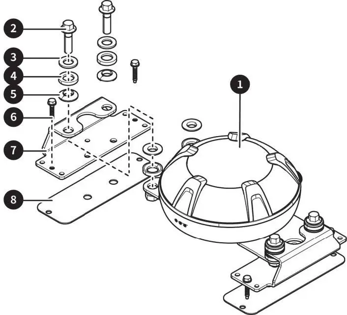
| No. | Name | Qty. | Remarks |
| 1 | GNSS receiver | ||
| 2 | Hexagon flange bolt M8x3Q | 4 | |
| 3 | Flat washer class A MS | 4 | |
| 4 | Spherical washer | 8 | |
| 5 | Taper washer | 8 | |
| 6 | Tapping screw | 4 | |
| 7 | GNSS receiver bracket | 2 | |
| 8 | 3M sticker | 4 |
Installation Steps
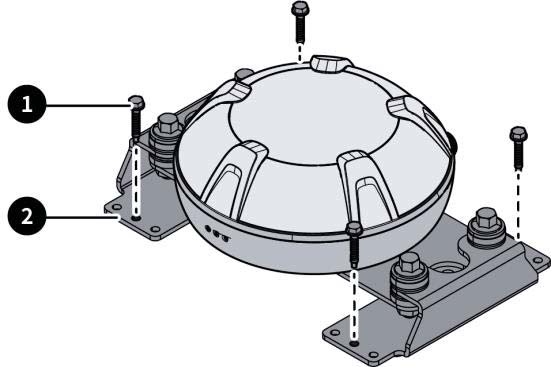
Install the GNSS receiver bracket on the top of the agricultural machinery with the flat washers, spherical washers, taper washers, and tapping screws or 3M stickers. The installation method is as follows:
- Step 1: The GNSS receiver is pre-installed on the bracket. Tighten the hexagon flange bolts 1. Use an appropriate number of washers 2 on both sides to ensure that the GNSS receiver is level.
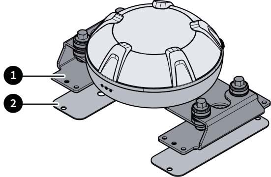
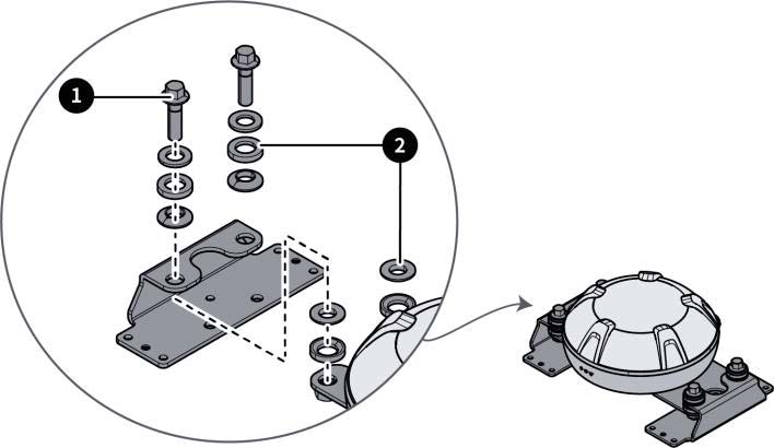 Step 2: Use the tapping screws or 3M stickers, whichever suitable, to fix the GNSS receiver on the top.
- Method 1: Use tapping screws 1 to fix the GNSS receiver bracket 2 on the top of the agricultural machinery.
- Method 2: Use the 3M stickers 1 to fix the GNSS receiver bracket 2.
- Method 1: Use tapping screws 1 to fix the GNSS receiver bracket 2 on the top of the agricultural machinery.
Installing the Terminal
Materials 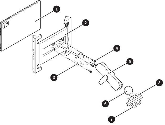
| No. | Name | Qty. | Remarks |
| 1 | Terminal | 1 | |
| 2 | Holder bracket | 1 | Provided with the terminal |
| 3 | Holder bracket base | 1 | |
| 4 | Screw | 4 | |
| 5 | Adapter bracket | 1 | |
| 6 | Bracket base | 1 | |
| 7 | U-bolt | 2 | |
| 8 | Nut | 4 |
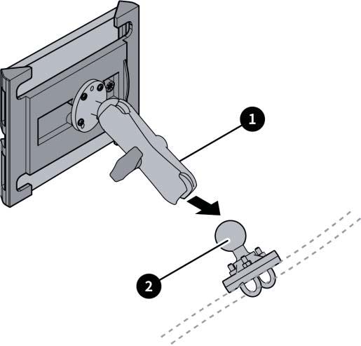
Installation Steps
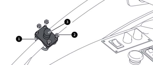
- Step 1: Select an appropriate position inside the cab for easy operation. Then, fix the bracket base 3 there with U-bolts 1 and nuts2.
- Step 2: Fix the bracket base 1 on the back of the terminal holder bracket 2 with screws and place in and fix the terminal 3 . Rotate the handle of the adapter bracket4 counterclockwise to loosen the ball socket, and then install the ball joint on the back of the terminal into the ball socket of the bracket.
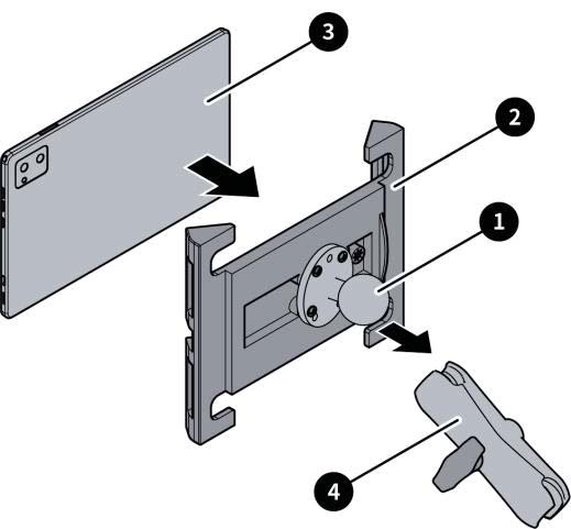
- Step 3: Install the ball joint 2 of the base into the other ball socket of the adapter bracket 1 , and rotate the handle clockwise to firmly fix the terminal.
Installing the SIM Card
Materials
| No. | Name | Qty. | Remarks |
| SIM card | The customer needs to prepare a micro-SIM card. |
 Note:
Note:
- Ensure that you have data traffic for the SIM card.
- Check whether you need to set the APN and network type according to the user manual after installing the SIM card. If you need to, turn on the terminal and configure them in the Android system settings.
Installation Procedure
- Locate the SIM card slot, insert the ejector into the hole on the slot, and press to eject the SIM card tray.
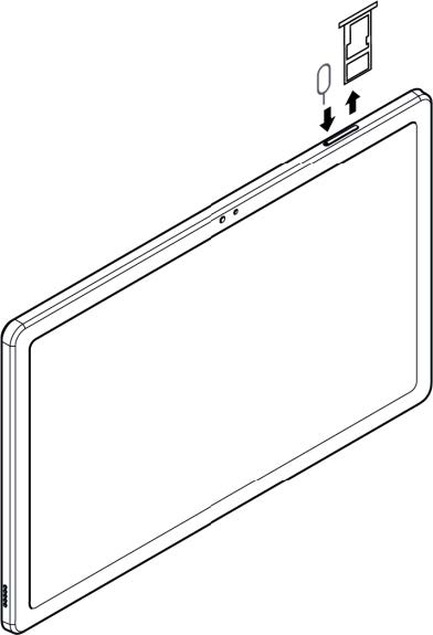
- Take out the SIM card tray, and put the SIM card into the tray. Be careful with the direction and ensure that the SIM card is level and fixed.
- Inset the SIM card try into the slot.
Installing Wiring Harnesses
Materials 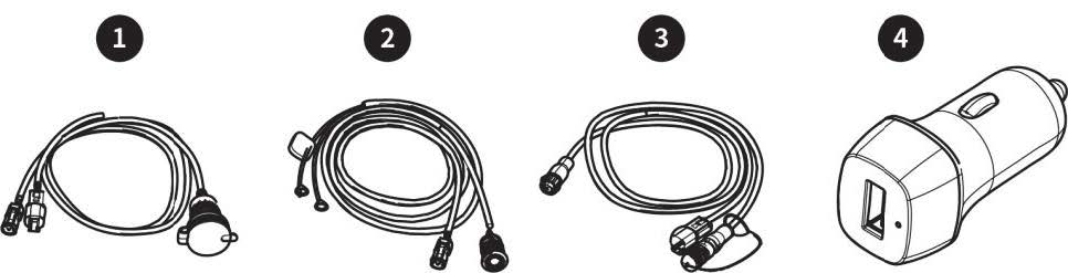
| No. | Name | Qty. | Remarks |
| 1 | Cab charger cable | 1 | |
| 2 | Main power cable | 1 | |
| 3 | GNSS receiver cable | 1 | |
| 4 | Cab charger | 1 |
Installation Procedure
Connect the cables according to the figure below.
Note:
- Turn off the agricultural machinery or its battery before plugging or unplugging cables or connecting devices.
- Avoid hot areas and sharp edges when wiring.
- Connect the main power cable to the negative electrode of the power supply, then to the positive electrode, and finally to other cables.
Suggestions:
- Route the GNSS receiver cable from the vehicle roof, for example, the sunroof, into the cab and to the right front of the seat.
- Connect the negative electrode of the main power cable to the negative electrode of the power supply, and do not connect the positive electrode to the power supply. Then, use nylon cable ties to fix the cable on the right side of the vehicle and into the cab from the right front.
- Connect one end of the cab charger cable to the main power cable and the other end to the GNSS receiver cable.
- To charge the terminal, connect the cab charger to the round end of the cab charger cable and connect port A of the USB A-Type-C cable to the cab charger (item Din the figure below) and the Type-C port to the terminal. If the agricultural machinery is equipped with a cigarette lighter (item E in the figure below), you can get power directly from it.

| l | GNSS receiver cable | A | GNSS receiver | E | Cab charger |
| 2 | Power cable | B | Terminal | F | Radio port |
| 3 | Cab charger cable | C | Power supply | G | Power switch |
| 4 | USB A-Type-C cable | D | Cab charger |
Copyright Notice:
SMAJAYU reserves the copyright for this manual and all contents herein. No part of this manual may be reproduced, extracted, reused, and/or reprinted in any form or by any means without the prior written permission of SMAJAYU.
This manual is subject to change without notice.
Revisions:
| Version | Date | Description |
| Rev. 1.0 | 2024.05 | First release |
System Commissioning
Site Conditions
- Ensure that the agricultural machinery is in good condition and all parts are functional.
- Ensure that there are no signal obstructions such as tall trees and buildings around the site.
- Ensure that there are no high-voltage power lines within 150 m around the site.
- The site ground should be level and no smaller than 50 m x 10 m.
- The site should have flat concrete pavement or asphalt pavement.
- Commissioning should be carried out on non-public roads. Ensure that no irrelevant personnel stay around the excavator during commissioning to prevent accidents.
Power-On
Check Before Power-on
- Check whether the power supply is connected correctly.
- Check whether the supply voltage is satisfactory.
Check After Power-on
Turn on the control terminal, and check whether the system program starts normally.
Parameter Calibration
Calibrate the implement parameters if there is any overlap or skip between guidance lines. Choose Menu > Device Settings > Calibration on the terminal, select whether to calculate the correction automatically or manually, and then tap Calibrate. The correction will be added to the accumulated correction. You can also tap the button again for correction. Tap Clear if you need to clear the correction and the accumulated correction.
The preceding commissioning procedure ensure that accurate navigation is available. Before proceeding, do the following:
Check the signal source connection – Check the task configuration – Create or select fields → Create or select a task →Create or select a boundary → Create or select a guidance line → Check the implement configuration→ Obtain the heading – Start the operation. For details, see the Agricultural Machinery Guidance System Software User Manual
Appendix
Hardware Specifications
| No. | Component | Specifications |
| 1 | Terminal | Size: 248x157x8mmBasic configuration: 10.36-inch capacitive touchscreen, LED backlight, 12oox2000 pixels, 400 nits, 6 GB RAM, 128 GB ROM Power supply: 5 V Signal sources: radio, satellite, and 4G; Wi-Fi and Bluetooth connection Operating temperature: -10°C to +55°CStorage temperature: -20°C to +70°C |
| 2 | GNSS receiver | Size: 162×64.5 mm Frequency: GPS LlC/ A, LlC, L2P(W), L2C, L5; GLONASS L1 and L2; BDS Bll, B2I, B31, BlC, and B2a;Galileo El, E5a, E5b, and SBAS Operating voltage: 9 V to 36 V Operating current: < 300 mA Operating temperature: -20°c to +70°C Storage temperature: -40°C to +85°CIP rating: IP66 |
Warranty
- All users who purchase the agricultural machinery guidance system enjoy a 2-year warranty, including lifetime free updates for the system software. The warranty period starts from the date of product sale (invoice issuance).
- Within the warranty period of the agricultural machinery guidance system, any damaged part will be repaired or replaced by the dealer free of charge if the warranty for the damaged part is valid. If the damaged part is out of the warranty period, the user needs to purchase a new part, and the dealer will repair the system for the user.
- If the agricultural machinery guidance system is damaged due to improper use, maintenance, or adjustment of the user, or other non-quality reasons during the warranty period, the user needs to purchase a spare part, and the dealer or SMAJAYU will repair the system free of charge.
- The dealer will provide free installation, debugging, training, and service within the warranty period of the agricultural machinery guidance system.
- SMAJAYU s reserves the right of interpretation for this warranty commitment.
Read Before Use:
 Install in strict accordance with this manual.
 If you have any questions during use, contact the service personnel.
Disclaimer:
- The purchased products, services, and features are stipulated by the contract. All or part of the products, services, and features described in this manual may not be within the scope of your purchase or usage. Unless otherwise specified in the contract, all the content in this manual is provided “AS IS” without warranties of any kind, express or implied.
- The content of this manual is subject to change due to product upgrades and other reasons. SMAJAYU reserves the right to modify the content of this manual without notice.
- This manual only provides guidance for use of this product. Every effort has been made in the preparation of this manual to ensure accuracy of the content, but no information in this manual constitutes a warranty of any kind, express or implied.
Preface
Thank you for using this SMAJAYU product. This manual provides detailed hardware installation guide. If you have any questions, contact the local dealer.
Purpose and Intended Users
This manual introduces the physical characteristics, installation procedures, and technical specifications of the product as well as the specifications and use of the wiring harnesses and connectors. Based on the assumption that the users are familiar with the terms and concepts related to this product, this manual is intended for users who have read the preceding content and have experience in hardware installation and maintenance.
Technical Support
SMAJAYU official website: www.smajayu.com For detailed information on installation, use and function updates, please contact us at tech@smajayu.com and support@smajayu.com.
FFCC statements
This device (FCC ID: 2BH4K-SMA10GPS) complies with part 15 of the FCC rules. Operation is subject to the following two conditions:
- This device may not cause harmful interference, and
- This device must accept any interference received, including interference that may cause undesired operation.
NOTE: The manufacturer is not responsible for any radio or TV interference caused by unauthorized modifications or changes to this equipment. Such modifications or changes could void the user’s authority to operate the? equipment.
NOTE: This equipment has been tested and found to comply with the limits for a Class B digital device, pursuant to part 15 of the FCC Rules. These limits are designed to provide reasonable protection against harmful interference in a residential installation. This equipment generates uses and can radiate radio frequency energy and, if not installed and used in accordance with the instructions, may cause harmful interference to radio communications. However, there is no guarantee that interference will not occur in a particular installation. If this equipment does cause harmful interference to radio or television reception, which can be determined by turning the equipment off and on, the user is encouraged to try to correct the interference by one or more of the following measures:
- Reorient or relocate the receiving antenna.
- Increase the separation between the equipment and receiver.
- Connect the equipment into an outlet on a circuit different from that to which the receiver is connected.
- Consult the dealer or an experienced radio/TV technician for help.
Federal Communication Commission (FCC) Radiation Exposure Statement When using the product, maintain a distance of 20cm from the body to ensure compliance with RF exposure requirements. Changes or modifications not expressly approved by the party responsible for compliance could void the user’s authority to operate the equipment.
©SMAJAYU. All rights reserved.
FAQ
- Q: What should I do if I encounter interference while using the device?
- A: If interference occurs, try adjusting the device’s position or moving it to a different location to minimize interference. Ensure no unauthorized modifications have been made.
- Q: How can I ensure compliance with RF exposure requirements?
A: Maintain a distance of at least 20cm between the device and your body while using it to comply with RF exposure requirements. - Q: Can I make modifications to the device for customization?
A: Only make modifications that are expressly approved by the responsible party for compliance to avoid voiding your authority to operate the equipment.
Documents / Resources
 |
SMAJAYU SMA10GPS GPS Tractor Multi Function Navigation System [pdf] Instruction Manual SMA10GPS, SMA10GPS GPS Tractor Multi Function Navigation System, GPS Tractor Multi Function Navigation System, Multi Function Navigation System, Navigation System |