scoutlabs Mini V2 Camera Based Sensors User Manual

Technical support
support@scoutlabs.ag
engineering@scoutlabs.ag
Informations
www.scoutlabs.ag
Hungary, Budapest, Bem József u. 4, 1027
![]() Bem József u. 4
Bem József u. 4

Package contents
The scoutlabs Mini package includes all components necessary for setup and operation. Verify the following items are included before starting. If any components are missing or damaged, contact customer support.
Included items are the following:

It is recommended to retain the packaging materials for off-season storage and transportation to and from the field. Note that the package does not include a sticky sheet or pheromone.
Trap assembly
To assemble and install the scoutlabs Mini trap for effective pest monitoring, follow these steps:
- Begin by unfolding the delta trap and ensuring it is clean and free from debris.

- Attach the scoutlabs Mini to the delta trap using the USB Type-C cable coming from the battery box. Secure the device by clipping the two mounting tabs on the top into place.
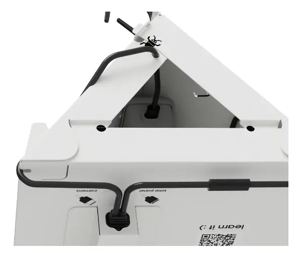
- Route the cable through the cable guidance holes to keep it properly aligned. This prevents accidental disconnection or damage.

- Insert the sticky sheet into the delta trap from the other side, aligning it with the four positioning tabs. These tabs lock the corners in place, ensuring the entire sheet is visible to the camera for accurate insect capture and monitoring.

- Close the sides of the delta trap by clipping them securely together.

- Connect the solar panel to the battery box, routing the cable through the cable guidance holes to keep it secure and close to the trap body.

- Finally, insert the plastic hanger into the delta trap to enable easy installation on your field.
For additional visual guidance and more detailed instructions, visit our website: https://scoutlabs.ag/learn/.
Trap setup and operation
The scoutlabs Mini is a fairly simple product, consisting of only a few parts. All of the important parts the user should interact with are named below:
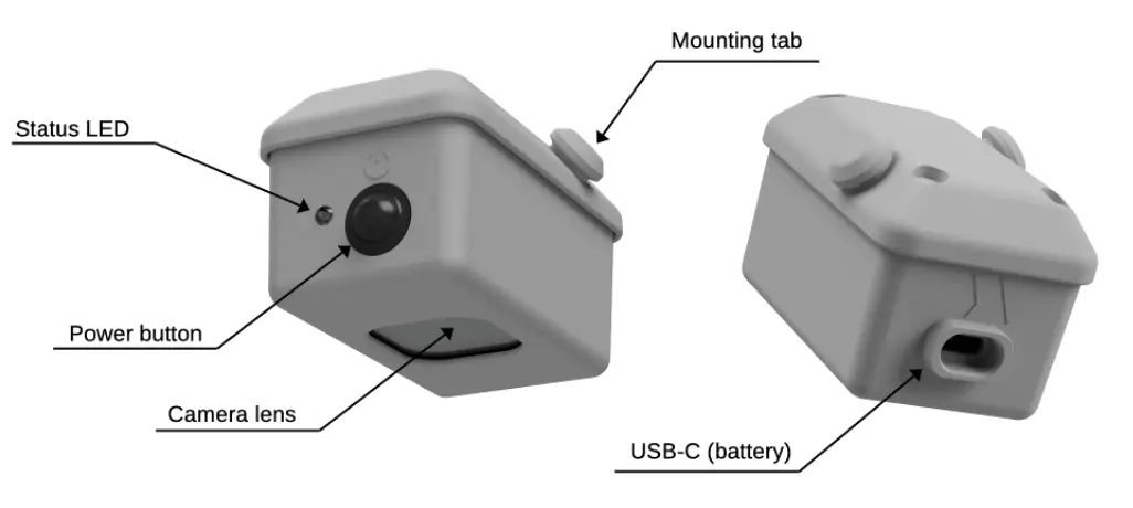

The battery should be connected to the scoutlabs Mini via the USB-C connector on the housing, while the solar panel should be connected to the charging connector (USB-C), coming out from the battery box. Operating the trap in normal mode is only recommended, when it is fully assembled, all of the connectors, cables and mounting points fixed.
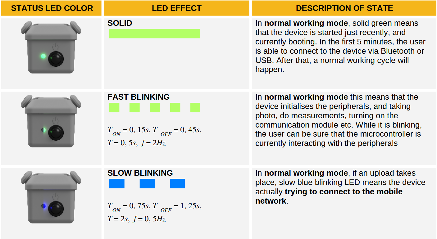
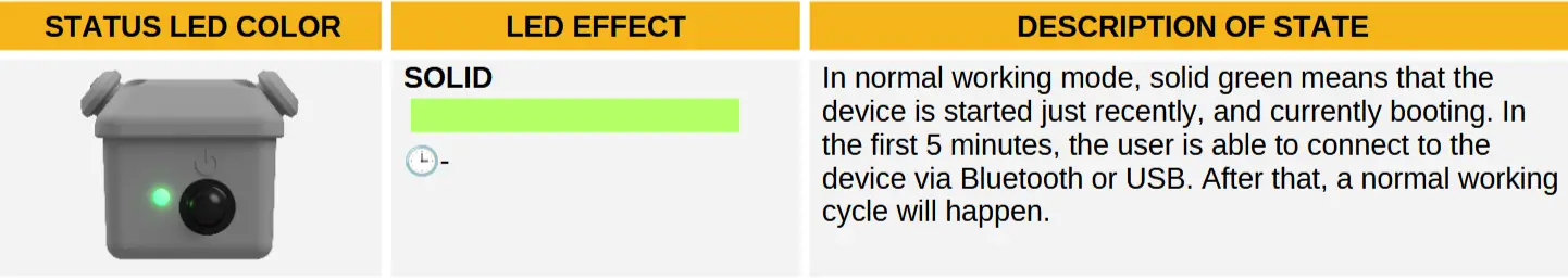
The scoutlabs Mini can be powered on by pressing the only button on the device, which is called ‘Power button’. Once turned on, the status LED will either blink yellow or display a solid green light, indicating the device’s activation status or working state. Refer to the next section for a detailed explanation of the LED signal meanings.
The user can easily set up the trap by using the ‘scoutlabs’ application which is available to download from the Apple App Store or the Google Play Store. Use the QR code on the left to download the application for your platform. The supported platforms are Android and iOS.

https://dashboard.scoutlabs.ag/api/qr-redirect/
By default, an out-of-the box scoutlabs Mini is deactivated, and the user should add it to their profile and activate it to start the monitoring. After turning on, the user has 5 minutes to communicate with the trap via Bluetooth Low Energy. Have a look at the steps of this process below. This is also guided by the scoutlabs application.
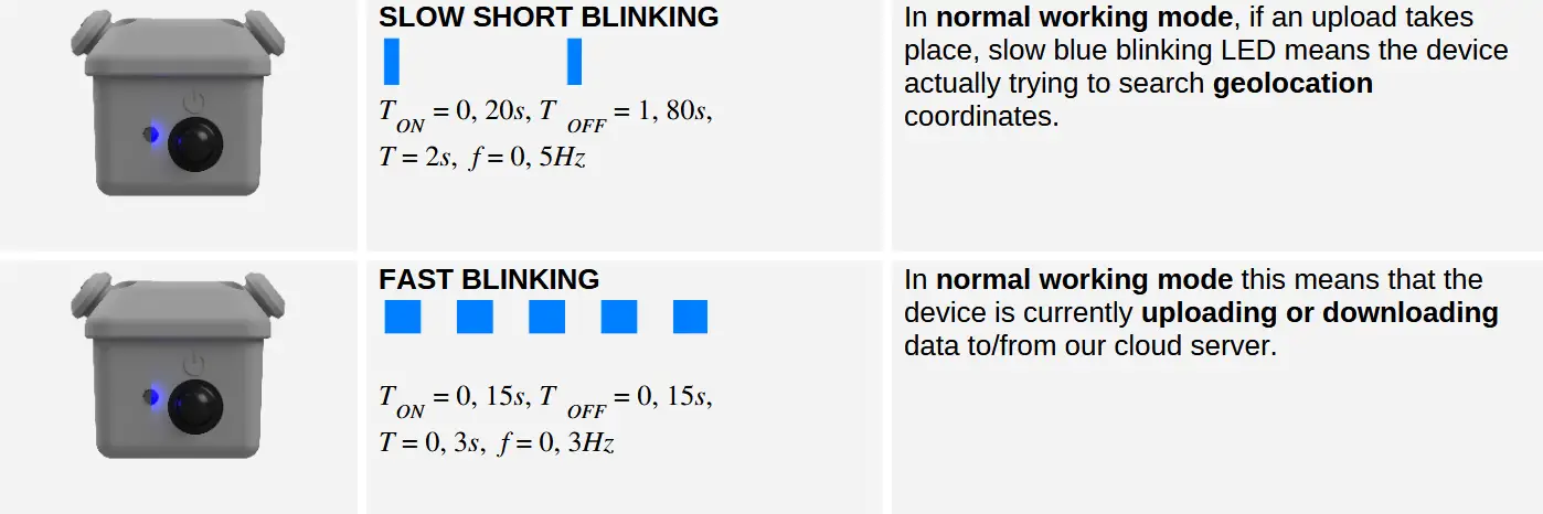
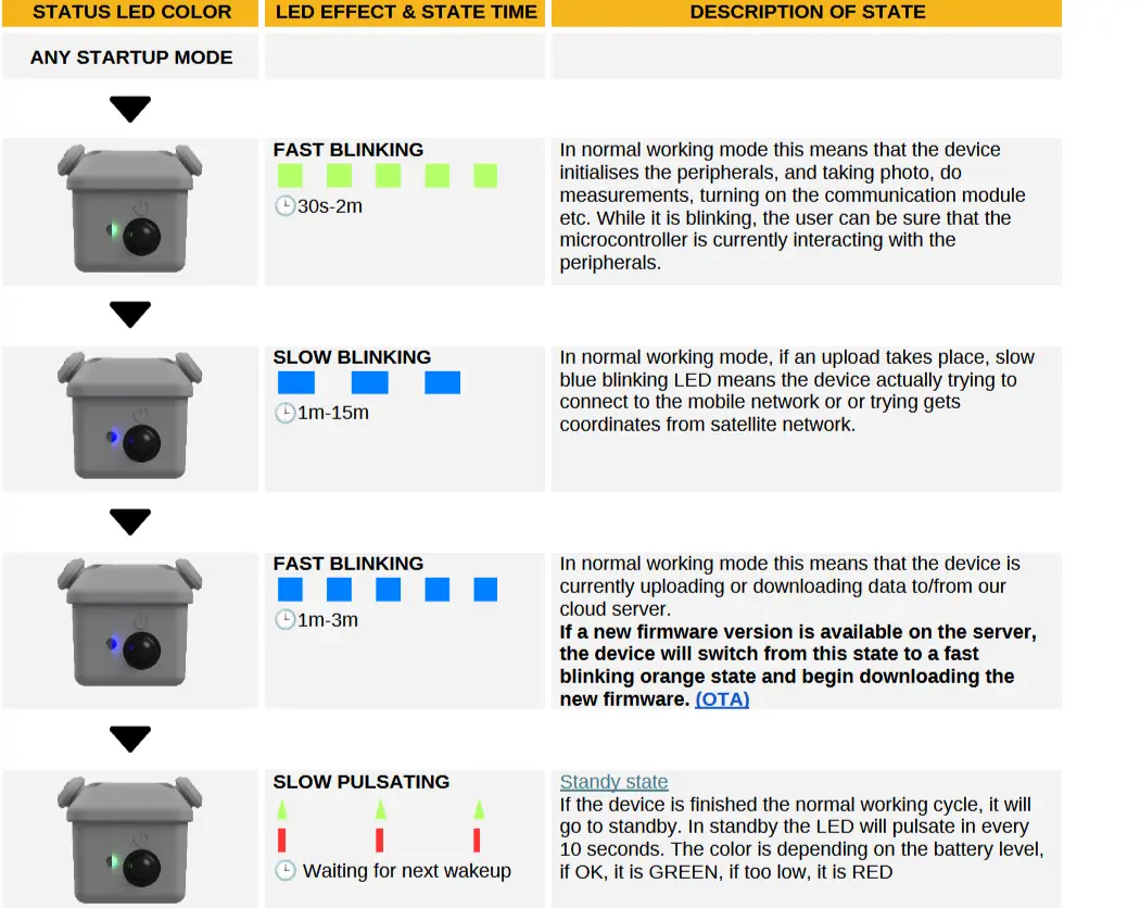
Status LED color meaning
The status LED effects indicate different states. It provides information about the current process taking place on the device or the state of the device.
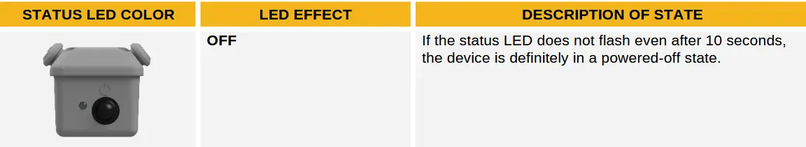
Powered OFF state
The device is in a powered-off state if the power button is in the off position, or if it is not connected to a power source via a USB cable. The device does not contain an internal battery.
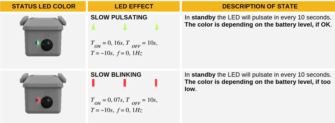
Standby state
The device enters standby state when, after normal operation, the device goes to sleep. The sleep mode can be similar to the powered-off state therefore, the status LED is used to distinguish between the powered-off state and the sleep mode.
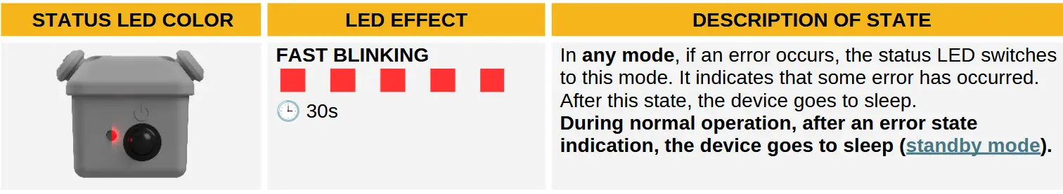
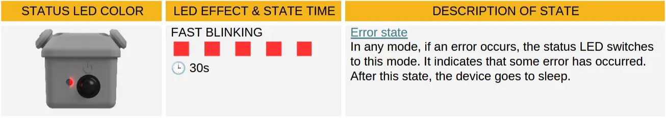
Error state
Error indicator status LED behavior.
Normal operational processes and states
Operational modes
The device can be started in three modes. This can be controlled by the number of power cycles with power button. The power cycles must be completed within 5 seconds.
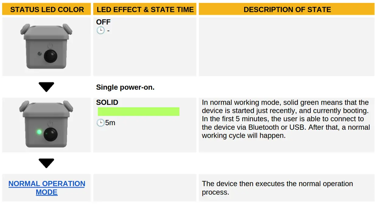
Normal startup
The normal start can be achieved by a single power-on. In this mode, it is possible to connect to the device via USB cable or Bluetooth.
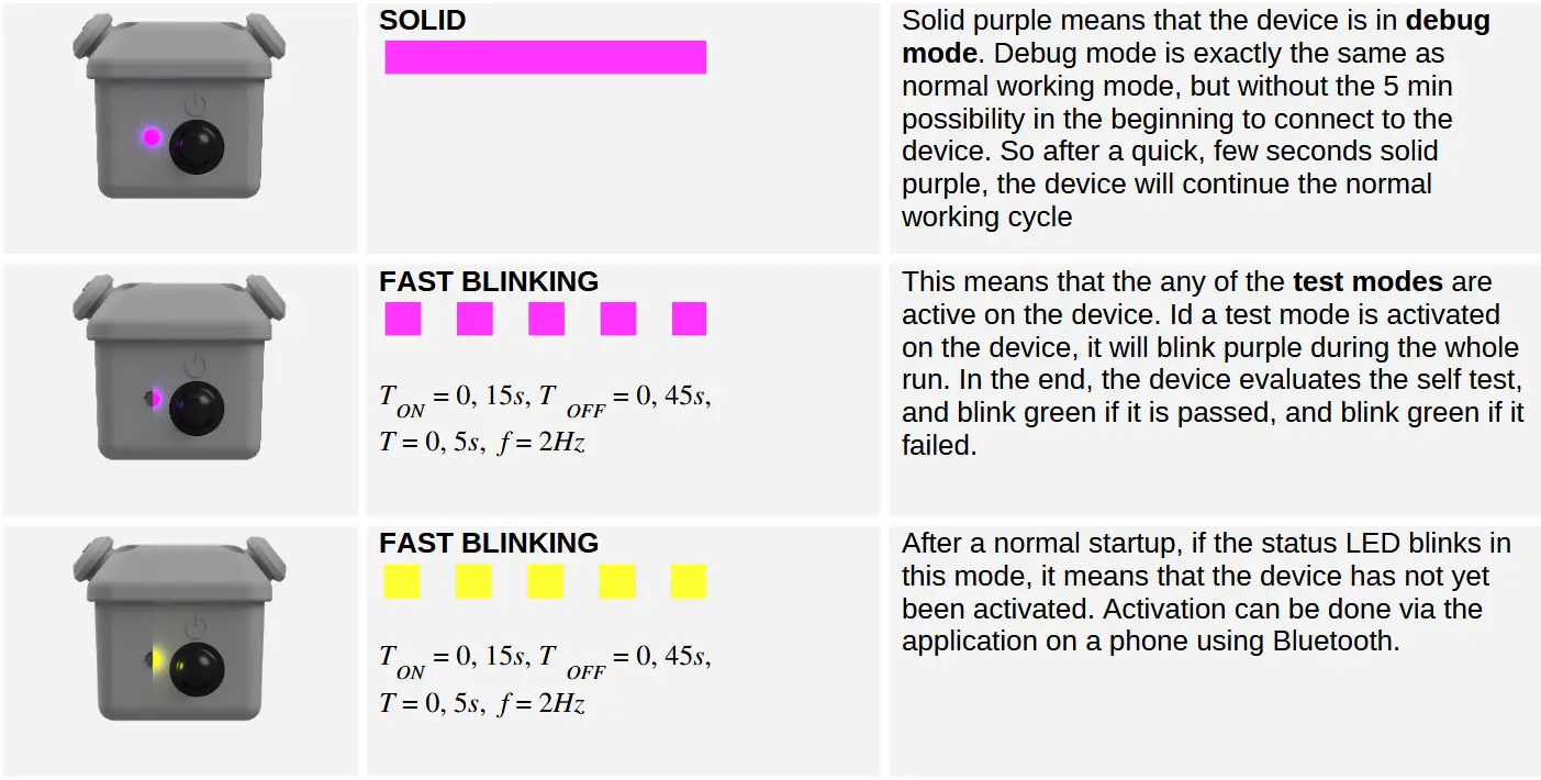
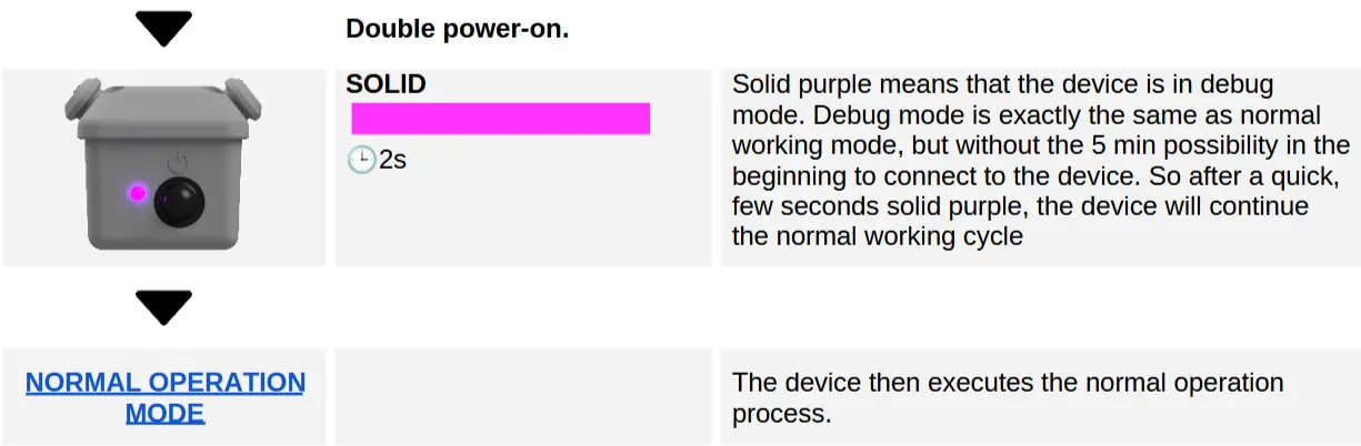
Debug mode
The debug start can be achieved by a double power-on. Debug mode is exactly the same as normal working mode, but without the 5 min possibility in the beginning to connect to the device.
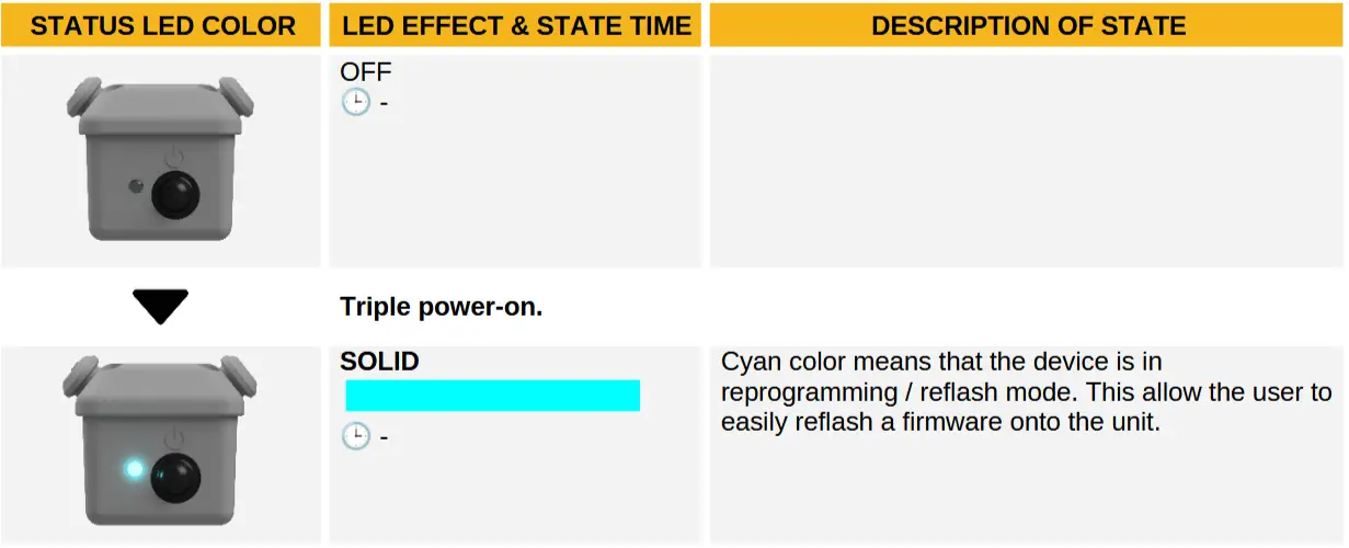
Flash mode
The flash mode start can be achieved by a triple power-on.
Wake up mode
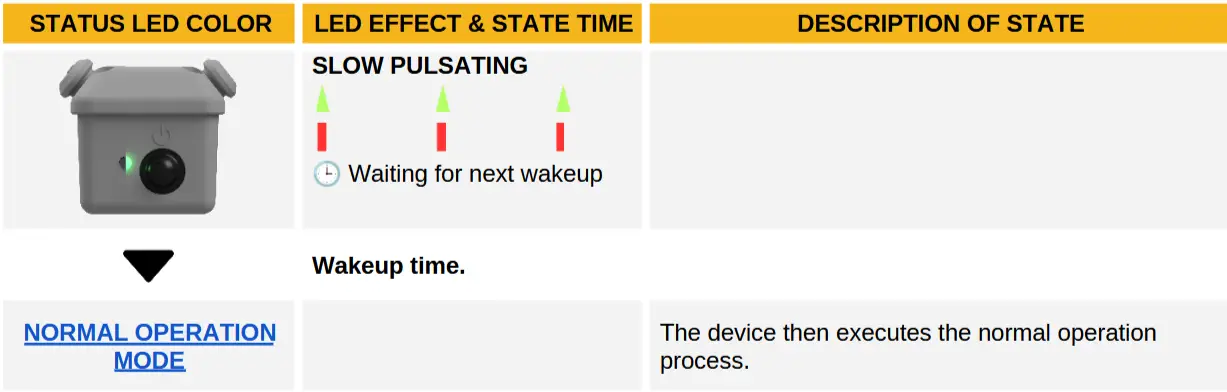
Normal operation mode
The following flowchart illustrates the normal operational mode. The possible initiation methods for the normal operational process will be described later in this document.
If any error occurs in the process, the device enters an error state.
Firmware update
The device firmware can be updated in three ways. The following will demonstrate this. It is important that with none of the methods do we directly flash the firmware onto the device. Instead, we copy the binary file to the device’s storage using any of the methods, and then the device will flash itself.
USB
For this method, we need to have the firmware.bin file on our computer and an USB-C data cable. At the 1. step, connect the computer to the TRAP Mini 2 and turn on with a normal mode start. After this, the device will be in the following state:
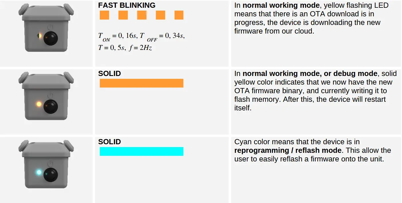
If the computer recognizes the device, then the 5 minute time in this state is not applicable. If the connection is successful, the device storage will appear on the computer. As the 2. step, copy the firmware.bin file from the computer to the device’s storage. This can take up to 1 minute. If the file has been successfully uploaded to the device, the third step is to start the device in debug mode. When the device starts, it detects that the firmware.bin file is on the storage, and begins to flash itself. The status LED will be as follows:
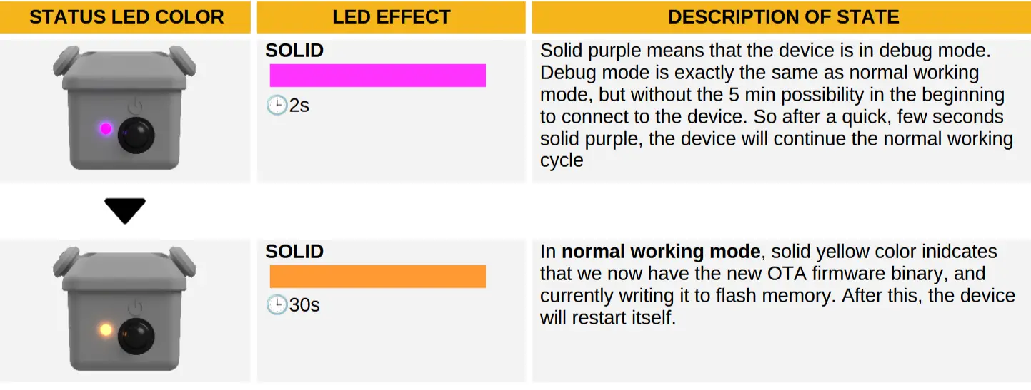
If the device has finished the flash process, it will restart itself, now with the new firmware version.
Bluetooth (Not supported)
This is not yet available in the current mobile application. As the first step, the device must be turned on with a normal mode start. In later versions, this also be available.
Over the air (OTA)
With this method, no human intervention is needed. Here, the device independently obtains the new firmware version from the server and then flashes itself. This can be done once the device has completed the network connection process and has requested the configuration file from the server. If a new firmware version is available, the device statuses will be as follows:
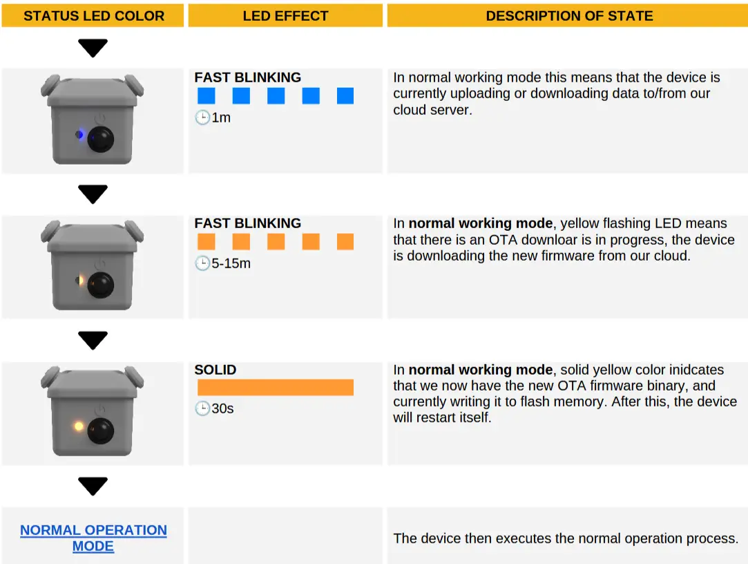
If the device has finished the flash process, it will restart itself, now with the new firmware version.
FCC Statement
- This device complies with Part 15 of the FCC Rules. Operation is subject to the following two conditions
(1) This device may not cause harmful interference.
(2) This device must accept any interference received, including interference that may cause undesired operation. - Changes or modifications not expressly approved by the party responsible for compliance could void the user’s authority to operate the equipment.
Note: This equipment has been tested and found to comply with the limits for a class B digital device, pursuant to Part 15 of the FCC Rules. These limits are designed to provide reasonable protection against harmful interference in a residential installation.
This equipment generates uses and can radiate radio frequency energy and, if not installed and used in accordance with the instructions,may cause harmful interference to radio communications. However, there is no guarantee that interference will not occur in a particular installation. If this equipment does cause harmful interference to radio or television reception, which can be determined by turning the equipment off and on, the user is encouraged to try to correct the interference by one or more of the following measures:
- Reorient or relocate the receiving antenna.
- Increase the separation between the equipment and receiver.
- Connect the equipment into an outlet on a circuit different from that to which the receiver is connected.
- Consult the dealer or an experienced radio/TV technician for help.
The device has been evaluated to meet general RF exposure requirements. This equipment should be installed and operated with a minimum distance of 20 cm between the radiator and your body.
Documents / Resources
 |
scoutlabs Mini V2 Camera Based Sensors [pdf] User Manual Mini V2 Camera Based Sensors, Camera Based Sensors, Based Sensors, Sensors |