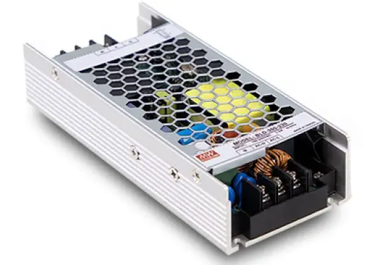
MEAN WELL VFD-350C-230 AC Input Variable Frequency Drive Module with PFC Function
Scan the code for manual and video:

Features
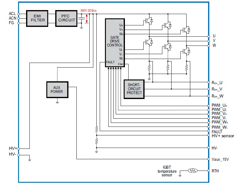
- 90~264Vac input, built-in PFC boost to 380VDC
- Power stage, 3-phase switches with sensors in one unit for external control (control board VFD-CB sold sperately)
- High peak current up to 200% and 5 seconds
- Fanless design for silent operation and long lifetime
- Protections: Short circuit / OCP
- Internal sensors feed out for control: Current sensor – motor torque control
- DC bus voltage sensor – OVP/UVP
- Temperature sensor – OTP
- -30~+60°C wide operating temperature
- Suitable for 3-phase motor drive (e.g. BLDC, Induction motor, SynRM)
- 3 years warranty
Applications
- HVAC
- Fan
- Water/Air pump
- Power tools
- Conveyor
- Automatic door
- Fitness equipment
GTIN CODE
- MW Search: https://www.meanwell.com/serviceGTIN.aspx
Description
The VFD-350C-230 is an universal variable frequency drive power module providing integrated power stage, gate drivers and basic VFD sensors such as three phase output current and temperature sensors. This product can be implemented for a three phase motor drive solution by coordinating with an external motor drive controller in logic level and analog 1/0. The power stage input is single phase full range from 90VAC to 264VAC with PFC function. The 3-phase motor output is up to 240V with 200% peak current capability. The VFD-350C-230 is suitable for three-phase motor drive, such as BLDC, Induction motor, and SynRM applications.
Model Encoding

SPECIFICATIONS
| MODEL NO. | VFD-350C-230 | ||||
|
PWM OUTPUT (Note 1,2,3,4) |
VOLTAGE RANGE(UVW) | 380Vmax, line-to-line voltage 0~268V adjustable with modulated PWM , suitable for 3PH 200-240V class motor | |||
| CURRENT | Rated | 1.4A | |||
| Peak | 2.8A for 5 seconds | ||||
| RATED POWER | 350W | ||||
| EFFICIENCY | 93% | ||||
| DC BUS VOLTAGE | 380±5VDC | ||||
| PWM FREQUENCY | 2.5 KHz ~ 15 KHz | ||||
|
INPUT |
RATED INPUT VOLTAGE | 90 ~ 264VAC | |||
| INPUT FREQUENCY RANGE (Hz) | 47 ~ 63Hz | ||||
| POWER FACTOR (Typ.) | PF>0.99/115VAC, PF>0.93/230VAC at full load | ||||
| RATED INPUT CURRENT | 3.5A /115VAC 2A/230VAC | ||||
| INRUSH CURRENT | Cold start 70A /230VAC | ||||
| LEAKAGE CURRENT | <2mA/240VAC | ||||
|
CONTROL / FUNCTION
(Note 5) |
3-PHASE PWM CONTROL | PWM control signal to gate driver for IGBTs. (CN93, PIN8~13)
3.3V TTL/CMOS input: High(>2.7V): IGBT ON ; Low(<0.4V): IGBT OFF |
|||
| 3-PHASE CURRENT SENSOR | Built-in 100mΩ low-side shunt resistors on UVW phase (CN93, PIN4~6) | ||||
| DC BUS VOLTAGE SENSOR | DC BUS voltage sensor output (CN93, PIN1) 2.5V@DC BUS 380V | ||||
| THERMAL SENSOR | Built-in 10KΩ NTC for sensing IGBTs operating temperature. (TSM2A103F34D1R (Thinking Electronic), PIN3 of CN93) | ||||
| FAULT SIGNAL | Inverter fault signal(Short circuit/OCP, CN93, PIN7).
3.3V TTL/CMOS output: Normal: High(>3V); Abnormal: Low(<0.5V) |
||||
| AUXILIARY POWER | Non-isolated 15V output power for external control board (CN93,PIN 14 to PIN2 ) 15V@0.1A ; Tolerance +/- 0.5V, Ripple 1Vp-p max | ||||
| PROTECTION | SHORT CIRCUIT | Protection type : Shut down o/p voltage, re-power on to recover | |||
|
ENVIRONMENT |
WORKING TEMP. | -30 ~ +60℃ (Refer to “Dreating Curve”) | |||
| WORKING HUMIDITY | 20 ~ 90% RH non-condensing | ||||
| STORAGE TEMP., HUMIDITY | -40 ~ +85℃, 10 ~ 95% RH non-condensing | ||||
| VIBRATION | 10 ~ 500Hz, 2G 10min./1cycle, period for 60min. each along X, Y, Z axes | ||||
|
SAFETY & EMC |
SAFETY STANDARDS | CB IEC61800-5-1,TUV/BS EN/EN61800-5-1,EAC TP TC004 approved | |||
| WITHSTAND VOLTAGE | I/P-FG:2KVAC | ||||
| ISOLATION RESISTANCE | I/P-FG:100M Ohms/500VDC/25℃/ 70%RH | ||||
|
EMC EMISSION |
Parameter | Standard | Test Level / Note | ||
| Conducted | BS EN/EN IEC61800-3 | Class A, C2 | |||
| Radiated | BS EN/EN IEC61800-3 | Class A, C2 | |||
| Harmonic Current | BS EN/EN IEC61000-3-2 | Class A | |||
| Voltage Flicker | BS EN/EN61000-3-3 | —– | |||
|
EMC IMMUNITY |
BS EN/EN IEC61800-3, second environment | ||||
| Parameter | Standard | Test Level /Note | |||
| ESD | BS EN/EN61000-4-2 | Level 3, 8KV air ; Level 2, 4KV contact | |||
| Radiated | BS EN/EN IEC61000-4-3 | Level 3 | |||
| EFT/Burest | BS EN/EN61000-4-4 | Level 3 | |||
| Surge | BS EN/EN61000-4-5 | Level 3, 2KV/Line-Earth ; Level 3, 1KV/Line-Line | |||
| Conducted | BS EN/EN61000-4-6 | Level 3 | |||
| Magnetic Field | BS EN/EN61000-4-8 | Level 4 | |||
| Voltage Dips and Interruptions | BS EN/EN IEC61000-4-11 | >95% dip 0.5 periods, 30% dip 25 periods,
>95% interruptions 250 periods |
|||
| Voltage deviation | IEC 61000-2-4 Class 2 | ±10% Un | |||
| Total Harmonic distortion (THD) Individual Harmonic orders | IEC 61000-2-4 Class 3
IEC 61000-4-13 Class 3 |
THD 12 % | |||
| Frequency variations | IEC 61000-2-4 | ±4% | |||
| Frequency rate of change | IEC 61000-2-4 | 2%/s | |||
|
OTHERS |
MTBF | 2078.9K hrs min.Telcordia SR-332 (Bellcore) ; 191.5K hrs min.MIL-HDBK-217F (25℃) | |||
| DIMENSION (L*W*H) | 146*62*31mm | ||||
| PACKING | 0.38Kg;32pcs/13.18kg/0.87CUFT | ||||
NOTE:
- 3-phase 220V motor is recommended. Please consider the rated current when used for 100-120V class motor.
- Refer to peak current capability in “V/I Curve”.
- Efficiency is tested with inductive load at rated current and full power.
- All parameters NOT specially mentioned are measured at 230VAC input, rated load and 25°C of ambient temperature.
- Please refer to “Functional Manual” for more details.
Product Liability Disclaimer: For detailed information, please refer to https://www.meanwell.com/serviceDisclaimer.aspx
Block Diagram
V/I CURVE
Derating Curve

Output Derating VS Input Voltage

Peak Current

Efficiency vs Load

Function Manual
- 3-phase PWM Control (CN93, PIN8~13)
VFD-350C-230 provides six-switch circuit by using 3 half-bridge IGBTs. IGBTs of each phase is controlled by PWM_UH/U,, PWM_V,N, and PWM_W,/W, (PIN 8~13). The input requirement for PWM is compatible with both TTL and CMOS 3.3V signals. Please refer to the diagram below.
WARNING: It is necessary to keep minimum dead-time between the upper and lower switch of each phase.

3-phase Current Detection & Overcurrent Protection (CN93, PIN4~6)
Low-side shunt resistors 100m are installed on each phase of VFD-350C-230 for current measurement and short-circuit detection. It’s suggested to shorten the length of external detection circuit and detect the signal with a OPAs. Please refer to diagram below.
If output current exceeds 200% of rated value, the internal protection circuit will be triggered and shut down the gate driver for protection.

DC BUS Voltage Detection (CN93, PIN1)
VFD-350C-230 is build-in with DC bus voltage sensor(HV+ sensor, PIN 1). The sensor provides a 2.5V output when DC bus voltage is at 380V. It’s suggested to detect the signal by OPAs. When the voltage of the DC bus exceed 420V, the PWM input signal must shut down for protection.
IGBT Temperature Detection (CN93, PIN3)
VFD-350C-230 is built-in a NTC resistor for detecting IGBTs temperature. Users can detect IGBTs temperature for protection. (NTC type: TSM2A103F34D1R, Thinking Electronic) The recommended detection circuit is below. It’s suggested to shutdown the PWMs input, if the temperture is above 100°C.

Fault signal
If the VFD-350C-230 encounters an overcurrent condition and remains in that state for the minimum overcurrent time, the FAULT signal will be activated (active low) to notify the external controller or circuit.

Brake Recommandations(CN100,PIN1,3)
VFD-350C-230 reserved CN100 PIN1,3 that connect to HV+,HV- for brake circuit design. The maximum voltage on DC Bus (HV+) shall not be higher than 420V.

Mechanical Specification

AC Inout Terminal Pin NO. Assianment (TB1).
| Pin No. | Assignment | ||
| 1 | AC/L | ||
| 2 | AC/N | ||
| 3 | |||
Output Terminal Pin NO. Assignment (TB100)
| Pin No. | Assignment |
| 1 | U |
| 2 | V |
| 3 | W |
380V DC Bus Connector(CN100): JST B3P-VH or equivalent
| Pin No. | Assignment |
| 1 | HV+ |
| 2 | No Pin |
| 3 | HV- |
- Mating housing: JST VHR or equivalent
- Terminal: JST SVH-21T-P1.1 or equivalent
- CN100 is used for installing regenerative brake device, avoiding VFD-350C-230 damage.
Control Pin NO. Assignment (CN93) : HRS DF11-14DP-2DS or equivalent
| Pin No. | Assignment | Pin No. | Assignment |
| 1 | HV+ sensor | 8 | PWM_W H |
| 2 | HV- | 9 | PWM_W L |
| 3 | RTH | 10 | PWM_V H |
| 4 | RSH _U | 11 | PWM_V L |
| 5 | RSH _V | 12 | PWM_U H |
| 6 | RSH _W | 13 | PWM_U L |
| 7 | FAULT | 14 | Vaux_15V |
- Mating housing: HRS DF 11-14DS or equivalent
- Terminal HRS DF11-**SC or equivalent
Control Pin No. Assignment(CN93):
| Pin No. | Function | Description |
| 1 | HV+ sensor | DC BUS voltage sensor output, reference to pin 2(HV-) |
| 2 | HV- | DC BUS voltage sensor output ground |
| 3 | RTH | Temperature sensor |
| 4 | RSH_U | U phase current sensor output |
| 5 | RSH_V | V phase current sensor output |
| 6 | RSH_W | W phase current sensor output |
| 7 | FAULT | Over current detection. Normal > 3V, Abnormal < 0.5V |
| 8 | PWM_WH | W phase high side logic input, on > 2.7V ; off < 0.4V |
| 9 | PWM_WL | W phase low side logic input, on > 2.7V ; off < 0.4V |
| 10 | PWM_VH | V phase high side logic input, on > 2.7V ; off < 0.4V |
| 11 | PWM_VL | V phase low side logic input, on > 2.7V ; off < 0.4V |
| 12 | PWM_UH | U phase high side logic input, on > 2.7V ; off < 0.4V |
| 13 | PWM_UL | U phase low side logic input, on > 2.7V ; off < 0.4V |
| 14 | Vaux_15V | Auxiliary voltage output 15V reference to pin2 (HV-). The maximum load current is 0.1A |
Application
Application example: BLDC drive application

- The figure shows a BLDC drive system set up with VFD-350C-230.
- Developers can control the PWM signal of 6-switch by using SPWM or SVPWM, etc. for 3-phase voltage modulation, and build the control method base on the current shunt sensors on 3-phase low-side switch(Rs-_U/V/W) and the DC BUS voltage sensor(HV+ sensor) which provided by VFD-350C-230.
- Developers can select the appropriate BLDC position sensors such as encoder or Hall-effect sensors to fit their applications.
- It’s suggested to install the brake circuit/device at the HV+/HV- pin( DC BUS,CN100) to avoid the DC BUS OVP when BLDC is decelerating.
- It’s suggested to shut down the PWM input or connect to brake resistor device for safety when DC Bus voltage is higher than 420V.
- If VFD-350C-230 was applied with non-appropriate control, such as accelerating too quickly or bad current control, it might trig the VFD-350C-230’s fault-state to shut down the output voltage low-level on FAULT pin).
Installation
- Operate with additional aluminum plate
In order to meet the “Derating Curve” and the “Static Characteristics”, VFD series must be installed onto an aluminum plate(or the cabinet of the same size) on the bottom. The size of the suggested aluminum plate is shown as below. And for optimizing thermal performance, the aluminum plate must have an even and smooth surface (or coated with thermal grease), and VFD series must be firmly mounted at the center of the aluminum plate.
- With 15CM forced air

Accessory List
If you have any control requirement of specific application, please consult MEAN WELL for more details. Motor control board (Motor control board and VFD drive module should be ordered separately):
Typical Application

- Variable Frequency Module (VFD series)
- Control board of Variable Frequency Drive (Designed by User or Soluton Provided by MEAN WELL)
- 3-phase Pump Motor

- Battery
- Variable Frequency Module (VFD series)
- Control board of Variable Frequency Drive (Designed by User or Soluton Provided by MEAN WELL)
- 3-phase Wheel Motor for AGV Application.

- Variable Frequency Module (VFD series)
- Control board of Variable Frequency Drive (Designed by User or Soluton Provided by MEAN WELL)
- 3-phase Fan Motor
- HEPA for Filtering Air
DEMO KIT
Please contact MEAN WELL for more detail.
VFD Demo Kit Main Function and Features.
- Built-in VFD-350P-230 and 230V motor.
- Motor start /stop/ forward/ reverse/speed control.
- Motor start/stop/forward /reverse indicator right.
- Motor speed (RDM) display.
- Control board replaceable.
- Support external motor connection.
Installation Manual
Please refer to: http://www.meanwell.com/manual.html.
Documents / Resources
 |
MEAN WELL VFD-350C-230 AC Input Variable Frequency Drive Module with PFC Function [pdf] Owner's Manual VFD-350C-230 AC Input Variable Frequency Drive Module with PFC Function, VFD-350C-230, AC Input Variable Frequency Drive Module with PFC Function, Frequency Drive Module with PFC Function, Module with PFC Function, PFC Function, Function |