S S REGELTECHNIK GW-wMODBUS-RAG Gateway with Modbus Module Wireless
Product Specifications
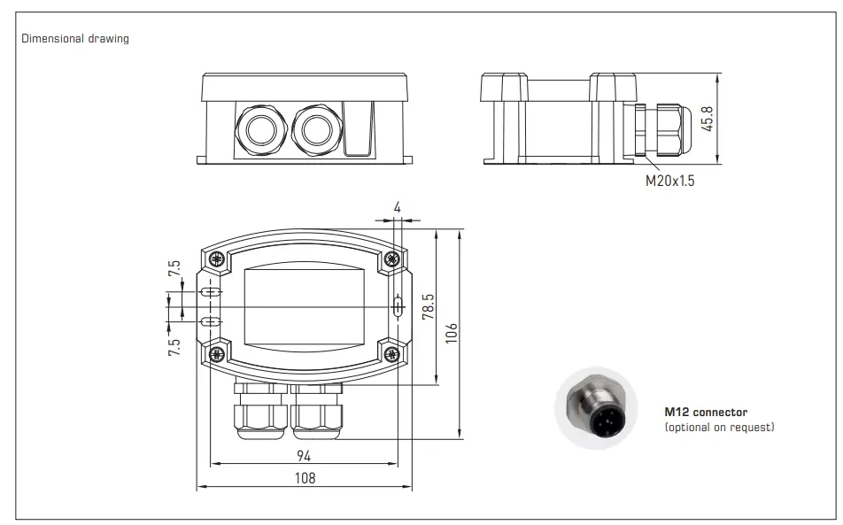
- Dimensions: 108 x 78.5 x 43.3 mm
- Power Supply: M20x1.5
- Communication: Modbus RTU / W-Modbus (Wireless)
- Operating Modes: Gateway, Node, Node Pro
- Range: Wireless
- Operating Temperature: < 95% RH, non-condensing air
- Protection Rating: IP65
Operating and Mounting Instructions
Gateway with W-Modbus module (Wireless), for radio-based connection to Modbus networks
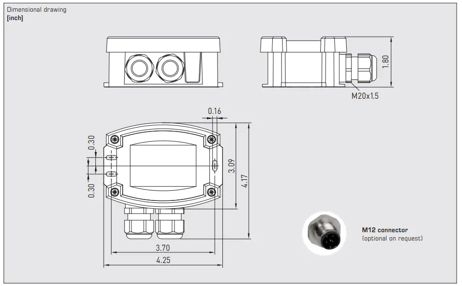
Dimensional drawing
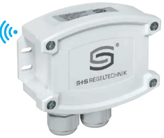
- The gateway KYMASGARD® GW-wModbus with Modbus connection and W-Modbus (wireless), in an impact-resistant plastic housing with quick-locking screws, for on-wall installation, serves as a transition between wired Modbus and radio-based W-Modbus.
- Up to 100 nodes can communicate with each other over a long distance (up to 500 m ⁄ 1640 ft in a free field).
- An electrically isolated RS485 transceiver is used on the wired side (bus parameters can be set via DIP switches).
- The simple setup of the wireless network and the connection stability enable existing systems to be easily expanded with wireless W-Modbus sensors. Even mixed configurations of wired and radio-based Modbus units can be easily integrated into existing network topologies via the
- W-Modbus gateway. For this purpose, there are two operating modes available depending on the unit type.
- Gateway operation for connection to an existing Modbus topology or directly to a DDC/PLC, serves as a base station for W-Modbus sensors (max. 100 wireless nodes). Node operation enables a wired Modbus sensor to be connected wirelessly to a W-Modbus network (max. 1 wired sensor). The extended Node Pro mode (for “GW-wModbusPro unit type”) is used to connect several wired Modbus sensors (max. 16 wired nodes).
- The innovative parametrisation feature of the W-Modbus interface and the elimination of Modbus wiring means that the entire W-Modbus network can be pre-configured (pairing the W-Modbus nodes, parametrising the gateway). This means that the network can be installed and put into operation quickly and easily at the destination. In App mode, the network setup can be checked and documented (PDF) using the Lumenradio W-Modbus app (Apple/Android). Other app functions also include installing firmware updates for the wireless module, changing unit names and recognising communication errors or duplicate addresses.
TECHNICAL DATA
- Power supply: 24 V AC (± 20 %); 15…36 V DC
- Power consumption: < 1.0 W ⁄ 24 VDC; < 1.4 VA ⁄ 24 VAC
- Communication: Modbus RTU (RS485 interface for RTU cable) and
- W-Modbus ((Wireless Modbus, frequency 2.4 GHz ISM, transmission power 100 mW, AES-128 encrypted)
- Range: max. 500 m ⁄ 1640 ft (open field) / approx. 50 – 70 m / 164 – 230 ft (inside buildings) between two wireless nodes
- Wireless nodes: max. 100 wireless nodess
- Operating modes: Gateway Basic function as a base station (DDC/PLC)
- Node Adapter function for max. 1 wired sensor (Type GW-wModbus)
- NodePro Adapter function for max. 16 wired sensors (Type GW-wModbusPro) (can be changed via DIP switch)
- Housing: Plastic, UV-resistant, polyamide material, 30 % glass-globe reinforced, with quick-locking screws (slotted ⁄ Phillips head combination), colour traffic white (similar to RAL 9016)
- Housing dimensions: 108 x 78.5 x 43.3 mm / 4.25 x 3.09 x 1.70 in (Tyr 3 without display)
- Cable connection: Cable gland, plastic (2x M 20 x 1.5; with strain relief, exchangeable, inner diameter 8 – 13 mm / 0.3 – 0.5 in)
- Electrical connection: 0.2 – 1.5 mm² / 24 – 16 AWG, using push-in terminals
- Ambient temperature: –30…+70 °C / –22…+158 °F
- Permitted humidity: < 95 % RH, non-precipitating air
- Protection class: III (according to EN 60 730)
- Protection type: IP 65 (according to EN 60 529)
- Standards: CE-conformity according to Radio Directive 2014 ⁄ 53 ⁄ EU
| Type ⁄ WG02 | Communication | Operating modes | Item no. |
| GW-wModbus | |||
| GW-w Modbus | Modbus RTU / W-Modbus (Wireless) | Gateway + Node | 1801-1211-1101-000 |
| GW-w Modbus Pro | Modbus RTU / W-Modbus (Wireless) | Gateway + Node Pro | 1801-1211-1101-100 |
| Note: “Pro” extends node operation from 1 to a maximum of 16 wired nodes | |||
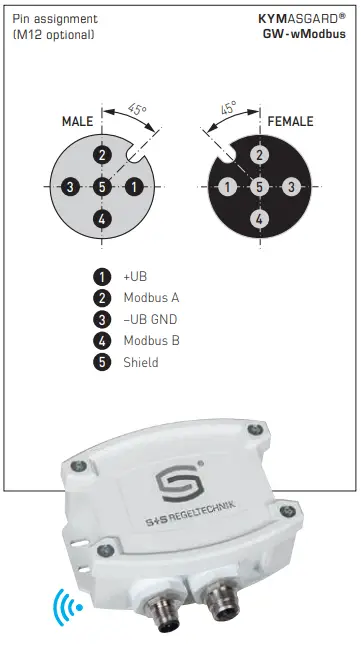
Pin assignment
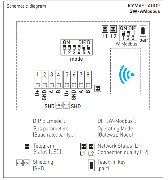
Schematic diagram
FUNCTION
W-Modbus networks can be set up without a Modbus controller connected. The connections of the paired W-Modbus units are retained, even if they are subsequently installed elsewhere!
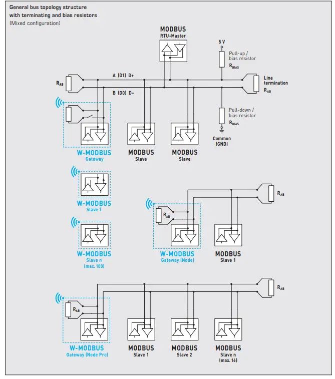
The KYMASGARD® GW-wModbus (Pro) gateway is compatible with all commercially available W-Modbus units based on Lumenradio MIRA technology. It comprises two units in one. The purpose within the network changes when you switch between the two operating modes. See illustration “Setting up the bus topology”.
Gateway → Base station (DDC/PLC)
“Gateway” operating mode (Master function) serves as a base station for W-Modbus units (max. 100 wireless nodes).
The master gateway is directly connected to a DDC/PLC.
The telegrams from the paired W-Modbus units are received wirelessly and forwarded to the DDC/PLC via RTU cable.
Node(Pro) → wireless adapter (slave)
- The “Node” operating mode (adapter function) serves as a W-Modbus adapter to wirelessly connect a Modbus unit (max. 1 wired node) to a W-Modbus network.
- The “Node Pro” operating mode (adapter function for unit type GW-Modbus-Pro) unit type expands the node operation to a maximum of 16 wired nodes.
- The Node(Pro) gateway (slave) communicates with the paired master gateway (DDC/PLC) like a W-Modbus sensor.
- The different ways of commissioning the two operating modes are described separately below – please follow the instructions!
Network installation
- The W-Modbus protocol is based on the 2.4 GHz ISM radio band and employs a patented frequency hopping technology to maximise reliability and resistance to interference.
- This means that reliable radio transmission can also be ensured in industrial environments.
- In the W-Modbus network, up to 100 nodes can communicate with each other over a long distance of up to 500 m (open field) using one gateway. A standardised W-Modbus module ensures compatibility with all W-Modbus units.
- The W-Modbus sensors only need to be supplied with power. Only the slave address is configured manually, the transmission parameters (baud rate and parity) are set automatically. No terminating resistor is required.
- The sensor is then paired with a gateway.
- The W-Modbus gateway can be installed anywhere along the Modbus line. It serves as a junction between a wired
- Modbus and radio-based W-Modbus. Even mixed configurations of wired and radio-based Modbus units can be easily integrated into existing network topologies via the W-Modbus gateway.
General configuration
GENERAL
- In the gateway’s factory setting, the bus parameters are set to 19200 8E1, and the bus termination is deactivated.
- The gateway is in secure gateway mode (“Gateway” – pairing deactivated).
- Status LED L1 is lit orange and L2 is lit green, telegram LED is lit green.
- The W-Modbus network can be set up without connection to a Modbus RTU bus!
- If Modbus communication needs to be active during commissioning, the Modbus DIP switches must be set to the parameters of the wired Modbus. The gateway can be connected anywhere in an existing Modbus. You might need to activate the terminating resistor.
APP MODE
- The Lumenradio W-Modbus app can access W-Modbus units.
- To do this, Bluetooth must be activated manually on the unit (using the “Pair” push-button).
- The unit then becomes visible and can be connected via the app.
- For further information, see “Commissioning” (“Pair” push-button).
In App mode, the Lumenradio W-Modbus app can access the gateway:
- Firmware updates of the wireless module
- Error detection (duplicate bus addresses, communication errors, etc.)
- Individual unit names
- Checking the network setup
- Documentation of the network setup (PDF)

You can find more information via the help function in the app.
- The app is available for Android and Apple mobile devices through the app store.
- Link for Apple Lumenradio W-Modbus app: https://apps.apple.com/en/app/w-modbus/id6472275984
- Link for Android Lumenradio W-Modbus app: https://play.google.com/store/apps/details?id=com.lumenradio.wmodbus

BUS PARAMETERS
| Baudrate
(selectable) |
DIP 1 | DIP 2 |
| 9600 Baud | ON | OFF |
| 19200 Baud (default) | ON | ON |
| 38400 Baud | OFF | ON |
| reserved | OFF | OFF |
| Parity
(selectable) |
DIP 3 |
| EVEN (default)
(numbered) |
ON |
| ODD
(numbered) |
OFF |
| Parity check
(on / off) |
DIP 4 |
| active (default)
(1 stop bit) |
ON |
| inactive (no parity) (2 stop bits) | OFF |
| 8N1 mode
(on / off) |
DIP 5 |
| active | ON |
| inactive (default) | OFF |
| Bus termination
(on/off) |
DIP 6 |
| active | ON |
| inactive (default) | OFF |
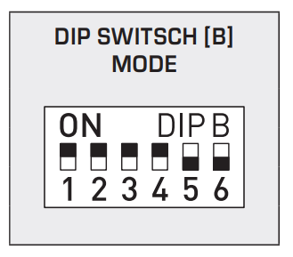
- The baud rate (speed of transmission) is set at DIP switches 1 and 2 of DIP switch block [B].
- Selectable are 9600 baud, 19200 baud (default), or 38400 baud – see table!
- Parity is set at DIP switch 3 of DIP switch block [B].
- Selectable are EVEN (default) or ODD – see table!
- Parity check is activated via DIP switch 4 of DIP switch block [B].
- Selectable are active (1 stop bit) (default), or inactive (2 stop bits), i.e. no parity check – see table!
- The 8N1 mode is activated via DIP switch 5 of DIP switch block [B].
- The functionality of DIP switch 3 (parity) and DIP switch 4 (parity check) of DIP switch block [B] is therefore deactivated. Selectable are 8N1 active or inactive (default) – see table !.
- Bus termination is activated via DIP switch 6 of DIP switch block [B].
- Selectable are active (bus termination resistance of 120 Ohm), or inactive (no bus termination) – see table!
Master Gateway (DDC/PLC)
DIP SWITCH
| Connection type
(Pairing mode) |
DIP 1 |
| Pairing active
(open connection) |
O N |
| Pairing deactivated (default) (secure connection) | OFF |
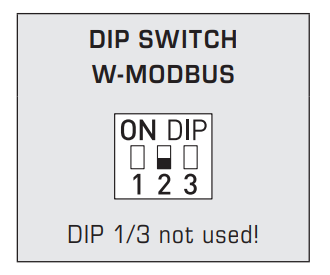
| Operating mode
(standard mode) |
DIP 2 |
| Gateway (default) (base station) | O N |
| Node(Pro) (wireless adapter) | OFF |
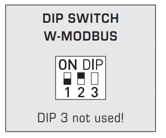
The connection type is set via pos. 1 of the “W-Modbus” DIP switch – see table!
The operating mode is set via pos. 2 of the “W-Modbus” DIP switch – see table!
To use it as a master gateway (base station on DDC/PLC), DIP 2 must be set to ON.
If the unit is switched over, it is unpaired and must be paired again in the network.
Pos. 3 of the “W-Modbus” DIP switch is not used.
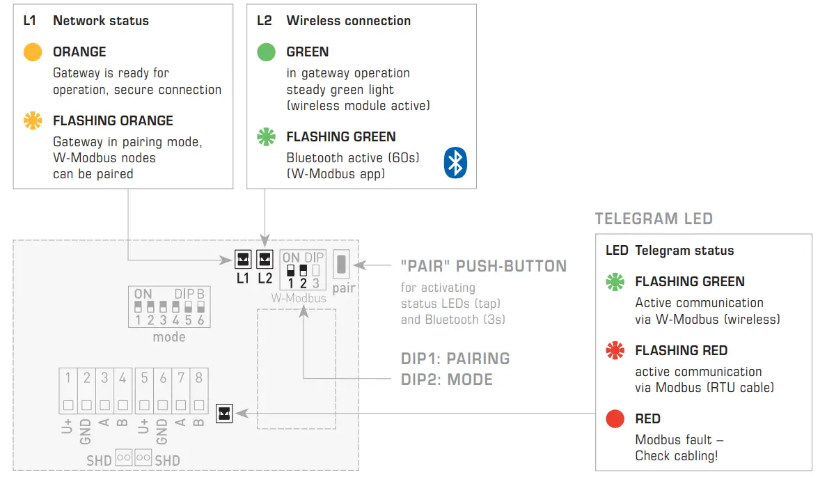
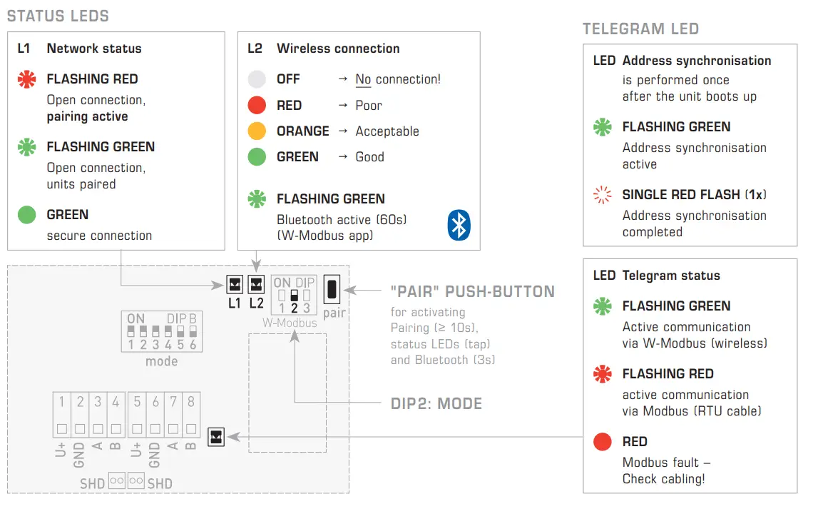
STATUS LEDS
The two LEDs L1 and L2 (on the left of the “Pair” push-button) indicate the wireless state of the sensor. They activate after the system is switched on and deactivate automatically after approx. 30 minutes.
If required, the LEDs can be reactivated manually using the “Pair” push-button.
TELEGRAM LED
The LED (on the right of the push-in terminals) flashes to indicate that Modbus communication is active. If there is a fault in the Modbus cables, the LED lights up red steadily.
“PAIR” PUSH-BUTTON
Different functions are assigned to the “Pair” push-button.
Briefly pressing the button (tap) activates the status LEDs for approx. 30 minutes.
A long press of the button (approx. 3 seconds) activates Bluetooth. The status LED L2 flashes green. The unit remains visible for approx. 60 seconds and can be detected by the Lumenradio W-Modbus app. The connection remains active until you press “Disconnect” in the app or activate Pairing mode on the unit.
STATUS LEDS
Master Gateway (DDC/PLC)
PAIRING “Gateway”
The network can be set up without connection to a Modbus RTU bus. If you intend testing Modbus communication during commissioning, you must set the Modbus parameters of the wired Modbus via DIP switches.
To pair a W-Modbus unit to a Gateway, you must set both units to Pairing mode. This also applies if the unit needs to be integrated into an existing network. Nodes that have already been paired are also automatically set to Pairing mode and paired again. Only one single master gateway (DDC/PLC) may be in Pairing mode at any one time in the immediate vicinity (wireless range)!
The master gateway (DDC/PLC) – hereinafter referred to as the Master Gateway – is paired in three simple steps:
- Activate pairing (open the connections)
The Master Gateway is activated via DIP switches:
DIP1 → ON (pairing active – open connection – status LED L1 flashes orange),
DIP 2 must stay on ON.
Please refer to the unit-specific operating instructions for the procedure for activating or deactivating Pairing mode on the W-Modbus unit.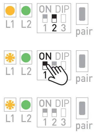
- Pair the units (set up a connection)
All W-Modbus units in active Pairing mode automatically search for a Master Gateway that is also set to pairing.
This initial connection setup can take approx. 1 – 2 minutes.
Now there is a temporary connection that can be secured as described in step 3. After approx. 2 – 3 minutes, it is already possible to test the Modbus communication and exchange data in this phase. - Deactivate pairing (secure the connections)
After all units have paired successfully, the user must manually terminate pairing on the Master Gateway: DIP1 → OFF (pairing deactivated – secure connection – Status-LED L1 lit orange)
This automatically deactivates the paired nodes. The W-Modbus units then perform an auto-restart and establish a secure connection. Modbus communication is re-established within 2 – 3 minutes.
A permanent connection is now established and remains even after the unit is restarted. Data exchange can begin in standard mode.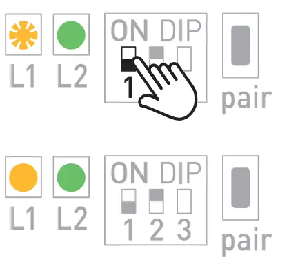
NOTES
Status LEDs turn off (LED L1 and L2 turn off)
- LEDs deactivate automatically after a 30-minute time-out.
The LEDs can be reactivated using the pair button (short push of button).
Error message (LEDs L1 and L2 flashing red) - Perform a reset: disconnect the unit from the power supply for approx. 1 minute, then switch it on again. If the error persists, please contact S+S Technical Support.
Node(Pro) Gateway (slave)
DIP SWITCH
| Not functional
in Node(Pro) mode |
DIP 1 |
| – | O N |
| – | OFF |
| Operating mode
(standard mode) |
DIP 2 |
| Gateway (default) (base station) | O N |
| Node(Pro) (wireless adapter) | OFF |
The operating mode is set via pos. 2 of the “W-Modbus” DIP switch – see table!
For use as a Node(Pro) gateway (wireless adapter for wired Modbus units), DIP 2 must be set to OFF.
If the unit is switched over, it is unpaired and must be paired again in the network.
Pos. 1 and 3 of the “W-Modbus” DIP switch are not used in Node mode.
STATUS LEDS
The two LEDs L1 and L2 (on the left of the “Pair” push-button) indicate the wireless state of the sensor. They activate after the system is switched on and deactivate automatically after approx. 30 minutes.
If required, the LEDs can be reactivated manually using the “Pair” push-button.
TELEGRAM LED
The LED (on the right of the push-in terminals) flashes to indicate that Modbus communication is active. If there is a fault in the Modbus cables, the LED lights up red steadily.
“PAIR” PUSH-BUTTON
Different functions are assigned to the “Pair” push-button.
Briefly pressing the button (tap) activates the status LEDsfor approx. 30 minutes.
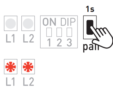
A long press of the button (≥ 10 seconds) activates Pairing.
Deactivation takes place automatically when you exit the Pairing mode on the master gateway.
A long press of the button (approx. 3 seconds) activates Bluetooth. The status LED L2 flashes green. The unit remains visible for approx. 60 seconds and can be detected by the Lumenradio W-Modbus app. The connection remains active until you press “Disconnect” in the app or activate Pairing mode on the unit.
MODBUS UNIT CONNECTION
The number of nodes depends on the unit type (1 node with GW-Modbus – max. 16 nodes with GW-ModbusPro).
The wired Modbus node is connected to Terminals A and B of the Node(Pro) gateway (DIP2 → OFF).
DIP switches [B] are used for setting the bus parameters. These may differ from the settings on the DDC/PLC.
Each of the connected Modbus units must be set to a unique bus address. After pairing the unit with the master gateway, you can change the bus address or connect additional nodes to the NodePro.
PAIRING “Node(Pro)”
To pair a Node(Pro) gateway (slave) to a master gateway (DDC/PLC), both units must be set to Pairing mode. This also applies if the unit needs to be integrated into an existing network. Nodes that have already been paired are also automatically set to Pairing mode and paired again. Only one master gateway may be in Pairing mode at any one time in the immediate vicinity (wireless range)! The Node(Pro) gateway can be optionally paired as standalone.
The Node(Pro) gateway (slave) – hereinafter referred to as the node-unit – is paired in three simple steps:
- Activate pairing (open the connections)
To activate “Pair mode” on the node unit, press the “Pair” push-button (long push of button for ≥ 10 seconds – DIP 2 must remain on OFF).
The status LEDs indicate that Pairing mode is active: L1 flashes red, L2 is turned off.
The process for activating or deactivating Pairing mode on the master gateway (DDC/PLC) can be found in the unit-specific operating instructions.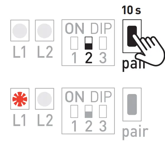
- Pair the units (set up a connection)
When Pairing mode is active, the Node unit automatically searches for a master gateway that is set to Pairing. This process can take approx. 1 – 2 minutes.
The status LEDs indicate the running processes: L1 flashes red – L2 is lit red
The status LEDs then indicate successful pairing: L1 flashes green – L2 is lit green or orange (depending on the quality of the wireless connection).
Note! If the unit is paired with a master gateway from a third-party provider,
the status LEDs indicate using different colours: L1 continues flashing red – L2 is lit green.
Now there is a temporary connection that can be secured as described in step 3.
After approx. 2 – 3 minutes, you can already test the Modbus communication and exchange data in this phase.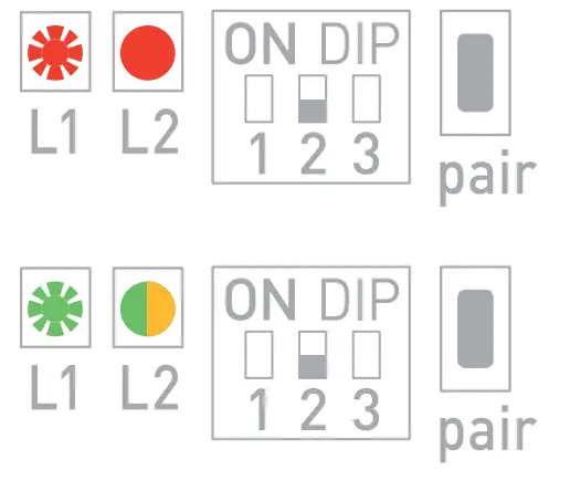
- Deactivate pairing (secure the connections)
After all units have paired successfully, the user must manually terminate pairing on the master gateway. This also terminates pairing on all paired units.
The node unit then performs an auto-restart and establishes a secure connection. Modbus communication is re-established within 2 – 3 minutes.
The status LEDs indicate the ongoing restart: first, L1 and L2 turn off.
The status LEDs then indicate that the connection is secure: L1 is lit green –
L2 is lit green, orange or red (depending on the quality of the wireless connection).
A permanent connection is now established and remains even after the unit is restarted. Data exchange can begin in standard mode.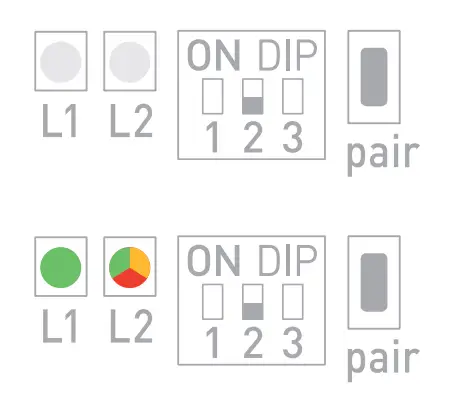
Important notes
S+S Regeltechnik GmbH hereby declares that the radio equipment type GW-wModbus complies with Directive 2014/53/EU.
The full text of the EU declaration of conformity is available at the following internet address: www.spluss.de/180112111101000/
Our “General Terms and Conditions for Business“ together with the “General Conditions for the Supply of Products and Services of the Electrical and Electronics Industry“ (ZVEI conditions) including supplementary clause “Extended Retention of Title“ apply as the exclusive terms and conditions.
In addition, the following points are to be observed:
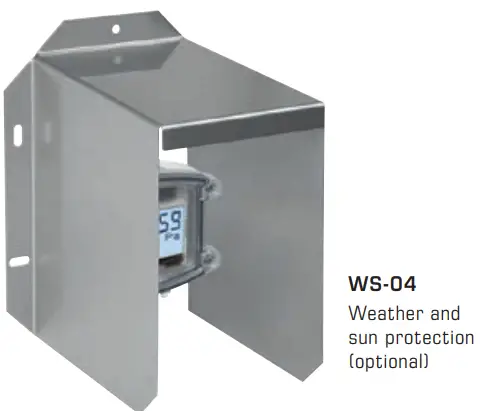
- A suitable weather and sun protection hood must be used when installed outdoors.
- To avoid damages and errors at the device (e.g. by voltage induction) shielded cables are to be used, laying parallel with current-carrying lines is to be avoided, and EMC directives are to be observed.
- This device shall only be used for its intended purpose. Respective safety regulations issued by the VDE, the states, their control authorities, the TÜV and the local energy supply company must be observed. The purchaser has to adhere to the building and safety regulations and has to prevent perils of any kind.
- No warranties or liabilities will be assumed for defects and damages arising from improper use of this device.
- Consequential damages caused by a fault in this device are excluded from warranty or liability.
- These devices must be installed and commissioned by authorised specialists.
- The technical data and connecting conditions of the mounting and operating instructions delivered together with the device are exclusively valid. Deviations from the catalogue representation are not explicitly mentioned and are possible in terms of technical progress and continuous improvement of our products.
- In case of any modifications made by the user, all warranty claims are forfeited.
- This device must not be installed close to heat sources (e.g. radiators) or be exposed to their heat flow. Direct sun irradiation or heat irradiation by similar sources (powerful lamps, halogen spotlights) must absolutely be avoided.
- Operating this device close to other devices that do not comply with EMC directives may influence functionality.
- This device must not be used for monitoring applications, which serve the purpose of protecting persons against hazards or injury,
or as an EMERGENCY STOP switch for systems or machinery, or for any other similar safety-relevant purposes. - Dimensions of enclosures or enclosure accessories may show slight tolerances on the specifications provided in these instructions.
- Modifications of these records are not permitted.
- In case of a complaint, only complete devices returned in original packing will be accepted.
These instructions must be read before installation and commissioning and all notes provided therein are to be regarded!
Safety notes
- Devices must only be connected to safety extra-low voltage and under dead-voltage condition.
- If power supplies with an output power greater than 15 W are used, additional safety measures (circuit breakers) must be implemented to limit the power output in the event of a fault.
- Commissioning is mandatory and may only be performed by qualified personnel!
Copyright by S+S Regeltechnik GmbH
Reprint in full or in parts requires permission from S+S Regeltechnik GmbH.
Subject to errors and technical changes. All statements and data herein represent our best knowledge at date of publication. They are only meant to inform about our products and their application potential, but do not imply any warranty as to certain product characteristics. Since the devices are used under a wide range of different conditions and loads beyond our control, their particular suitability must be verified by each customer and/or end user themselves. Existing property rights must be observed. We warrant the faultless quality of our products as stated in our General Terms and Conditions.
Bus address, binary coded
Frequently Asked Questions
- Q: What is the range of the wireless connection?
A: The wireless range is specified by the manufacturer and is suitable for typical installations within a specified distance. - Q: How many devices can be connected to the gateway?
A: The gateway supports multiple nodes and can handle up to 16 connected devices in Node Pro mode. - Q: How do I adjust the communication settings?
A: Use the DIP switches to configure bus parameters, baud rate, parity, and other communication settings as needed.
Documents / Resources
 |
S S REGELTECHNIK GW-wMODBUS-RAG Gateway with Modbus Module Wireless [pdf] Instruction Manual GW-wMODBUS-RAG, 6000-3610-0000-1XX, GW-wMODBUS-RAG Gateway with Modbus Module Wireless, GW-wMODBUS-RAG, Gateway with Modbus Module Wireless, Modbus Module Wireless, Module Wireless |