D3 Engineering 2ASVZ-02 DesignCore mmWave Radar Sensor

Product Information
Specifications
- Model: RS-6843AOP
Product Usage Instructions
INTRODUCTION
This document describes how to use the D3 Engineering Design Core® RS-1843AOP, RS-6843AOP, and RS-6843AOPA single-board mm Wave sensor modules. The sensors covered in this integration guide have an identical form factor and interfaces. Here is a summary of the different models. More information can be found in the data sheet for the given device.
Table 1. RS-x843AOP Models
| Model | Device | Frequency Band | Antenna Pattern | Qualification (RFIC) |
| RS-1843AOP | AWR1843AOP | 77 GHz | Azimuth Favored | AECQ-100 |
| RS-6843AOP | IWR6843AOP | 60 GHz | Balanced Az/El | N/A |
| RS-6843AOPA | AWR6843AOP | 60 GHz | Balanced Az/El | AECQ-100 |
MECHANICAL INTEGRATION
Thermal and Electrical Considerations
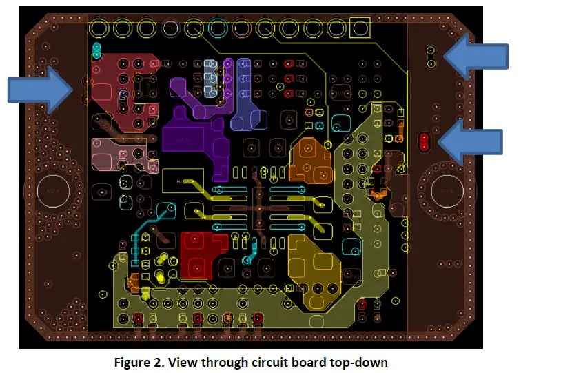
The sensor board has to evacuate up to 5 Watts to avoid overheating. The design includes two surfaces that should be thermally coupled to some form of heatsink that is designed to perform this transfer. These are at the side edges of the board where the screw holes are. A polished metal surface should contact the bottom of the board from the edge approximately 0.125” inward. The surface can be relieved to avoid shorting three via areas on the bottom. There is solder mask over the vias that provides insulation, however in an environment with vibration it is safest to create a void above them. Figure 2 shows the locations of the via areas.
Antenna Orientation
It should be noted that the application firmware can operate with any orientation of the sensor, but some prebuilt applications may assume a given orientation. Please verify that the orientation configured in the software matches the actual placement of the sensor.
Enclosure and Radome Considerations
It is possible to create a cover over the sensor, but the cover must appear invisible to the radar by making it a multiple of a half wavelength in the material. More on this can be found in section 5 of TI’s application note found here: https://www.ti.com/lit/an/spracg5/spracg5.pdf. D3 Engineering offers consulting services on Radome design.
INTERFACES
There is just one interface for the RS-x843AOP module, a 12-pin header. The header is Samtec P/N SLM-112-01-G-S. There are several mating options. Please consult Samtec for different solutions.
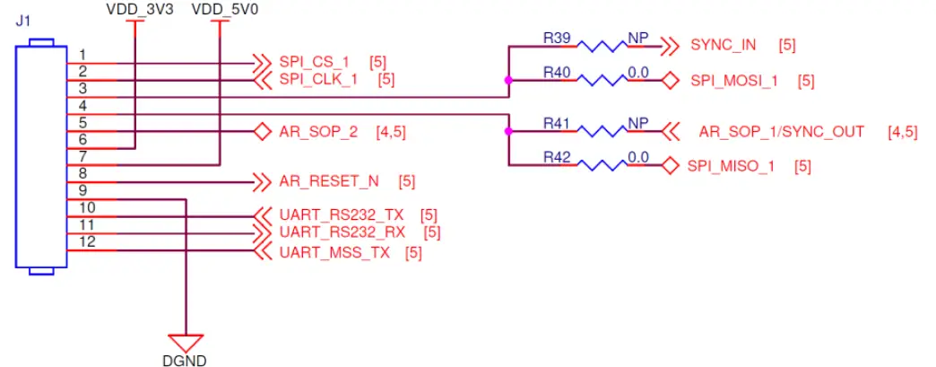
Figure 3. 12-Pin Header
Please reference the table below for more details on the header pinout. Please note that most I/Os can be used as general purpose I/Os as well, depending on the software loaded. These are denoted with an asterisk.
Table 2. 12-Pin Header Pin List
| Pin Number | Device Ball Number | Direction WRT Sensor | Signal Name | Function / Device Pin Functions | Voltage Range |
| 1* | C2 | Input | SPI_CS_1 | SPI Chip Select GPIO_30 SPIA_CS_N CAN_FD_TX |
0 to 3.3 V |
| 2* | D2 | Input | SPI_CLK_1 | SPI Clock GPIO_3 SPIA_CLK CAN_FD_RX DSS_UART_TX |
0 to 3.3 V |
| Pin Number | Device Ball Number | Direction WRT Sensor | Signal Name | Function / Device Pin Functions | Voltage Range |
| 3* | U12/F2 | Input | SYNC_IN SPI_MOSI_1 | Synchronization Input
SPI Main Out Secondary In |
0 to 3.3 V |
| 4* | M3/D1 | Input or Output | AR_SOP_1 SYNC_OUT SPI_MISO_1 | Boot option input Synchronization Output SPI Main In Secondary Out SOP[1], GPIO_29, SYNC_OUT, DMM_MUX_IN, SPIB_CS_N_1, SPIB_CS_N_2 GPIO_20, SPIA_MISO, CAN_FD_TX |
0 to 3.3 V |
| 5* | V10 | Input | AR_SOP_2 | Boot option input, high to program, low to run SOP[2], GPIO_27, PMIC_CLKOUT, CHIRP_START, CHIRP_END, FRAME_START, EPWM1B, EPWM2A |
0 to 3.3 V |
| 6 | N/A | Output | VDD_3V3 | 3.3 Volt output | 3.3 V |
| 7 | N/A | Input | VDD_5V0 | 5.0 Volt input | 5.0 V |
| 8 | U11 | Input and Output | AR_RESET_N | Resets RFIC NRESET | 0 to 3.3 V |
| 9 | N/A | Ground | DGND | Voltage Return | 0 V |
| 10 | U16 | Output | UART_RS232_TX | Console UART TX (note: not RS-232 levels) GPIO_14, RS232_TX, MSS_UARTA_TX, MSS_UARTB_TX, BSS_UART_TX, CAN_FD_TX, I2C_SDA, EPWM1A, EPWM1B, NDMM_EN, EPWM2A |
0 to 3.3 V |
| 11 | V16 | Input | UART_RS232_RX | Console UART RX (note: not RS-232 levels) GPIO_15, RS232_RX, MSS_UARTA_RX, BSS_UART_TX, MSS_UARTB_RX, CAN_FD_RX, I2C_SCL, EPWM2A, EPWM2B, EPWM3A |
0 to 3.3 V |
| 12 | E2 | Output | UART_MSS_TX | Data UART TX (note: not RS-232 levels) GPIO_5, SPIB_CLK, MSS_UARTA_RX, MSS_UARTB_TX, BSS_UART_TX, CAN_FD_RX |
0 to 3.3 V |
SETUP
The RS-x843AOP Sensor is programmed, configured, and started via the Console UART.
Requirements
- TI mm Wave SDK: https://www.ti.com/tool/MMWAVE-SDK
- TI Uniflash Utility: https://www.ti.com/tool/UNIFLASH
- TI mm Wave Visualizer: https://dev.ti.com/gallery/view/mmwave/mmWave_Demo_Visualizer/ver/3.5.0/
- RS-232 to TTL adapter (with Ribbon cable to mate with the header) or D3 AOP USB Personality board
- 5 Volt supply, rated for at least 1.5 A
Programming
To program, the board must be reset or powered up with the AR_SOP_2 signal (pin 5) held high for the rising edge of reset. Following this, use a PC serial port with an RS-232 to TTL adapter or a PC USB port with the AOP USB personality board to communicate with the sensor over pins 10 and 11. Ensure there is a ground connection to the board from the adapter as well. Use TI’s Uni flash utility to program the Flash connected to the RFIC. The demo application is found within the mm Wave SDK. For example: “C:\ti\mmwave_sdk_03_05_00_04\packages\ti\demo\xwr64xx\mmw\xwr64xxAOP_mmw_demo.bin”. D3 Engineering offers many other customized applications as well.
Running the Application
To run, the board must be reset or powered up with the AR_SOP_2 signal (pin 5) open or held low for the rising edge of reset. Following this, a host can communicate with the command line of the sensor. If you are using a host with RS-232 levels, an RS-232 to TTL adapter must be used. The command line depends on the application software running, but if using the mmWave SDK demo application, you can find the command line documentation within your install of the SDK. You may also use the TI mm Wave Visualizer to configure, run, and monitor the sensor. This can be run as a web application or downloaded for local use. With the standard demo application, data output from the sensor is available on pin 12 (UART_MSS_TX). The data format is described within the documentation for the mm Wave SDK. Other software may be written that performs other functions and uses the peripherals differently.
Table 3. Revision History
| Revision | Date | Description |
| 0.1 | 2021-02-19 | Initial Issue |
| 0.2 | 2021-02-19 | Added Other Pin Functions and Radome and Antenna Information |
| 0.3 | 2022-09-27 | Clarifications |
| 0.4 | 2023-05-01 | Addition of FCC Statements for RS-1843AOP |
| 0.5 | 2024-01-20 | Correction to FCC and ISED statements for RS-1843AOP |
| 0.6 | 2024-06-07 | Further corrections to FCC and ISED statements for RS-1843AOP |
| 0.7 | 2024-06-25 | Addition of Modular Approval Class 2 Permissive Change Test Plan |
| 0.8 | 2024-07-18 | Refinement of Limited Modular Approval information |
| 0.9 | 2024-11-15 | Added compliance section for RS-6843AOP |
RS-6843AOP RF Compliance Notices
The following RF emissions statements apply exclusively to the RS-6843AOP model radar sensor.
FCC and ISED Identification Label
The RS-6843AOP device has been certified to be in compliance with FCC Part 15 and ISED ICES-003. Due to its size the required FCC ID including the grantee code is included in this manual below.
FCC ID: 2ASVZ-02
Due to its size the required IC ID including the company code is included in this manual below.
IC: 30644-02
FCC Compliance Statement
This equipment has been tested and found to comply with the limits for a Class A digital device, pursuant to part 15 of the FCC Rules. These limits are designed to provide reasonable protection against harmful interference when the equipment is operated in a commercial environment. This equipment generates, uses, and can radiate radio frequency energy and, if not installed and used in accordance with the instruction manual, may cause harmful interference to radio communications. Operation of this equipment in a residential area is likely to cause harmful interference in which case the user will be required to correct the interference at his own expense.
This device complies with Part 15 of the FCC Rules. Operation is subject to the following two conditions:
- This device may not cause harmful interference, and
- This device must accept any interference received, including interference that may cause undesired operation. Please note that changes or modifications not expressly approved by the party responsible for compliance could void the user’s authority to operate the equipment.
Changes or modifications not expressly approved by the party responsible for compliance could void the user’s authority to operate the equipment.
FCC RF Exposure Statement
This equipment complies with FCC radiation exposure limits set forth for an uncontrolled environment. This transmitter must not be co-located or operating in conjunction with any other antenna or transmitter. In order to avoid the possibility of exceeding the FCC radio frequency exposure limits, this equipment should be installed and operated with minimum distance 20 cm (7.9 in) between the antenna and your body during normal operation. Users must follow the specific operating instructions for satisfying RF exposure compliance.
ISED Non-Interference Disclaimer
This device contains licence-exempt transmitter(s)/receiver(s) that comply with Innovation, Science and Economic Development Canada’s licence-exempt RSS(s).
Operation is subject to the following two conditions:
- This device may not cause interference.
- This device must accept any interference, including interference that may cause undesired operation of the device.
This device complies with the Canadian ICES-003 Class A specifications. CAN ICES-003(A) / NMB-003 (A).
ISED RF Exposure Statement
This equipment complies with ISED RSS-102 radiation exposure limits set forth for an uncontrolled environment. This equipment should be installed and operated with minimum distance 20 cm (7.9 inches) between the radiator and any part of your body. This transmitter must not be co-located or operating in conjunction with any other antenna or transmitter.
Outdoor operation
This equipment’s intended operation is outdoor only.
FCC and ISED Modular Approval Notice
This module was approved under a Limited Modular Approval, and because the module has no shielding, each other host which is not identical in construction/material/configuration would have to be added through a Class II Permissive Change with appropriate assessment following C2PC procedures. This section provides module integration instructions as per KDB 996369 D03.
List of Applicable Rules
See section 1.2.
Summary of the Specific Operational Use Conditions
This Modular Transmitter is approved for use only with specific antenna, cable and output power configurations that have been tested and approved by the manufacturer (D3). Modifications to the radio, the antenna system, or power output, that have not been explicitly specified by the manufacturer are not permitted and may render the radio non-compliant with applicable regulatory authorities.
Limited Module Procedures
See the remainder of this integration guide and section 1.8.
Trace Antenna Designs
There are no provisions for external trace antennas.
RF Exposure Conditions
See section 1.3.
Antennas
This device employs an integrated antenna which is the only configuration approved for use. Changes or modifications not expressly approved by the party responsible for compliance could void the user’s authority to operate the equipment.
Label and Compliance Information
The end product must carry a physical label or shall use e-labeling following KDB 784748 D01 and KDB 784748 stating: “Contains Transmitter Module FCC ID: 2ASVZ-02, IC: 30644-02” or “Contains FCC ID: 2ASVZ-02, IC: 30644-02”.
Information on Test Modes and Additional Testing Requirements
See section 1.8.
Additional Testing, Part 15 Subpart B Disclaimer
This modular transmitter is only FCC authorized for the specific rule parts listed on the grant, and the host product manufacturer is responsible for compliance to any other FCC rules that apply to the host not covered by the modular transmitter grant of certification. The final host product still requires Part 15 Subpart B compliance testing with the modular transmitter installed.
EMI Considerations
While this module was found to pass EMI emissions alone, care should be taken when used with additional RF sources to prevent mixing products. Best design practices should be used with regard to electrical and mechanical design to avoid creating mixing products and to contain/shield any additional EMI emissions. A host manufacturer is recommended to use D04 Module Integration Guide recommending as “best practice” RF design engineering testing and evaluation in case non-linear interactions generate additional non-compliant limits due to module placement to host components or properties. This module is not sold separately and is not installed in any host except for the Grantee of this modular certification (Define Design Deploy Corp.). In case where the module will be integrated in other Define Design Deploy Corp.’s non-identical hosts in the future, we will expand the LMA to include the new hosts after an appropriate assessment to the FCC rules.
Class 2 Permissive Change Test Plan
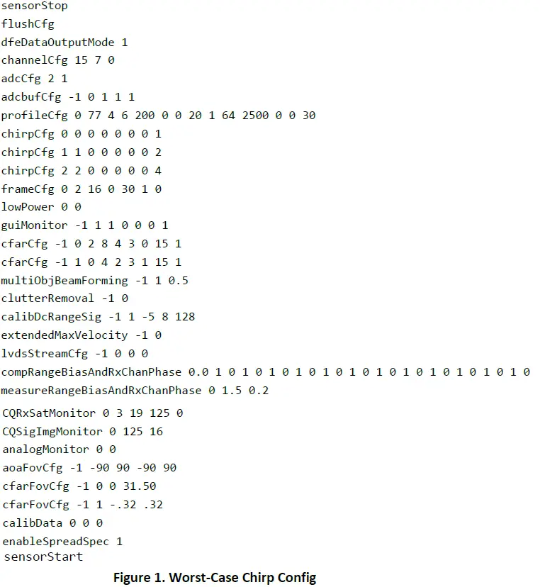
This module is limited to the specific host of Define Design Deploy Corp, Model: RS-6843AOPC. When this module is to be used in an end device with a different host type, the end device must be tested to ensure compliance has been maintained, and the results must be submitted by Define Design Deploy Corp. dba D3 as a Class 2 Permissive Change. To perform the testing, the worst-case chirp profile should be hard-coded in the firmware or input into the command UART port to begin operation as listed in Figure 1 below.
After this configuration is activated, proceed to test compliance to the applicable agency specifications as described below.
Test Objective: Verify the electromagnetic emissions of the Product.
Specifications:
- Transmit output power according to FCC Part 15.255(c), with limits of 20 dBm EIRP.
- Spurious unwanted emissions according to FCC Part 15.255(d), with limits below 40 GHz according to FCC 15.209 within bands listed in FCC 15.205, and limit of 85 dBμV/m @ 3 m above 40 GHz
Setup
- Place the Product on the turn platform within the anechoic chamber.
- Position the measurement antenna on the antenna mast at a distance of 3 meters from the Product.
- For fundamental power set transmitter to operate in continuous mode on the highest aggregate power, and highest power spectral density to confirm continued compliance.
- For band edge compliance, set the transmitter to operate in continuous mode on the widest and the narrowest bandwidths per modulation type.
- For radiated spurious emissions up to 200 GHz the following three parameters should be tested:
- Widest bandwidth,
- Highest aggregate power, and
- Highest power spectral density.
- If according to the radio module’s initial test report these conditions do not all combine in the same mode, then multiple modes should be tested: set transmitter to operate in continuous mode at low, mid and top channels with all the supported modulations, data rates and channel bandwidths until the modes with these three parameters have been tested and confirmed.
Rotation and Elevation:
- Rotate the turn platform 360 degrees.
- Gradually raise the antenna from 1 to 4 meters.
- Purpose: Maximize emissions and verify compliance with Quasi-peak limits below 1 GHz and Peak/Average limits above 1 GHz; and compare with the appropriate limits.
Frequency Scans:
- Initial scan: Cover frequency ranges from 30 MHz to 1 GHz.
- Subsequent scan: Change measurement setup for above 1 GHz measurements.
Verification:
- Verify fundamental emission levels, according to FCC Part 15.255(c)(2)(iii) within passband 60–64 GHz.
- Check harmonics according to FCC Part 15.255(d).
Extended Scans:
- Continue scanning for frequency ranges:
- 1–18 GHz
- 18–40 GHz
- 40–200 GHz
Spurious Emissions:
- Verify against quasi-peak, peak and average limits.
RS-6843AOP RF Special Compliance Notices
The following RF emissions statements apply exclusively to the RS-6843AOP model radar sensor.
FCC Compliance Statement
CFR 47 Part 15.255 Statement:
Limitations for use are as follows:
- General. Operation under the provisions of this section is not permitted for equipment used on satellites.
- Operation on aircraft. Operation on aircraft is permitted under the following conditions:
- When the aircraft is on the ground.
- While airborne, only in closed exclusive on-board communication networks within the aircraft, with the following exceptions:
- Equipment shall not be used in wireless avionics intra-communication (WAIC) applications where external structural sensors or external cameras are mounted on the outside of the aircraft structure.
- Except as permitted in paragraph (b)(3) of this section, equipment shall not be used on aircraft where there is little attenuation of RF signals by the body/fuselage of the aircraft.
- Field disturbance sensor/radar devices may only operate in the frequency band 59.3-71.0 GHz while installed in passengers’ personal portable electronic equipment (e.g., smartphones, tablets) and shall comply with paragraph (b)(2)(i) of this section, and relevant requirements of paragraphs (c)(2) through (c)(4) of this section.
- Field disturbance sensors/radar devices deployed on unmanned aircraft may operate within the frequency band 60-64 GHz, provided that the transmitter not exceed 20 dBm peak EIRP. The sum of continuous transmitter off-times of at least two milliseconds shall equal at least 16.5 milliseconds within any contiguous interval of 33 milliseconds. Operation shall be limited to a maximum of 121.92 meters (400 feet) above ground level.
ISED Compliance Statement
According to RSS-210 Annex J, the devices certified under this annex are not permitted to be used on satellites.
Devices used on aircraft are permitted under the following conditions:
- Except as allowed in J.2(b), devices are only to be used when the aircraft is on the ground.
- Devices used in-flight are subject to the following restrictions:
- They shall be used within closed, exclusive on-board, communication networks within the aircraft
- They shall not be used in wireless avionics intra-communication (WAIC) applications where external structural sensors or external cameras are mounted on the outside of the aircraft structure
- They shall not be used on aircraft equipped with a body/fuselage that provides little or no RF attenuation except when installed on unmanned air vehicles (UAVs) and complying with J.2(d)
- Devices operating in the 59.3-71.0 GHz band shall not be used except if they meet all of the following conditions:
- They are FDS
- They are installed within personal portable electronic devices
- They comply with the relevant requirements in J.3.2(a), J.3.2(b) and J.3.2(c)
- Devices’ user manuals shall include text indicating restrictions shown in J.2(a) and J.2(b).
- FDS devices deployed on UAVs shall comply with all of the following conditions:
- They operate in the 60-64 GHz band
- The UAVs limit their altitude operation to the regulations established by Transport Canada (e.g. altitudes below 122 metres above ground)
- They comply with J.3.2(d)
Copyright © 2024 D3 Engineering
Frequently Asked Questions (FAQ)
- Q: What is the FCC ID for the RS-6843AOP model?
A: The FCC ID for this model is 2ASVZ-02. - Q: What are the compliance standards for the RS-6843AOP radar sensor?
A: The sensor complies with FCC Part 15 and ISED ICES-003 regulations.
Documents / Resources
 |
D3 Engineering 2ASVZ-02 DesignCore mmWave Radar Sensor [pdf] Installation Guide 2ASVZ-02, 2ASVZ02, 2ASVZ-02 DesignCore mmWave Radar Sensor, 2ASVZ-02, DesignCore mmWave Radar Sensor, mmWave Radar Sensor, Radar Sensor, Sensor |