Auto-Connect MFAST Multi Function Audio System Tester
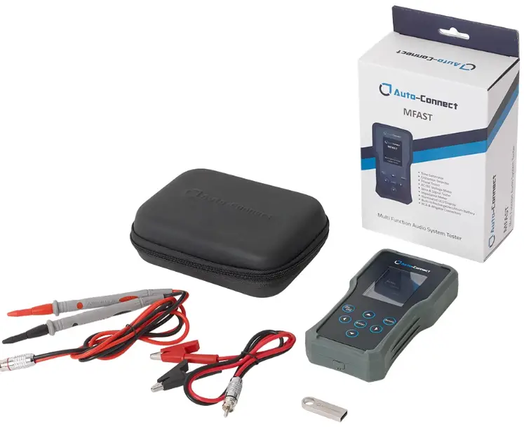
AUTO-CONNECT MULTI-FUNCTION AUDIO SYSTEM TESTER
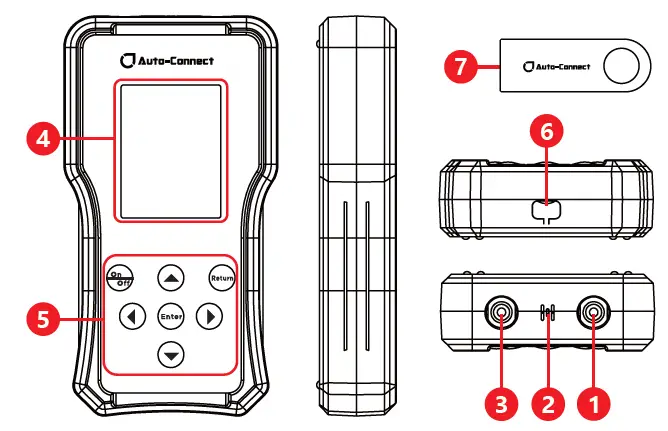
- Multi-functional input/output port
- Microphone
- RCA audio cable testing auxiliary interface
- LCD display screen
- Buttons
- Charging port
- USB flash drive (for storing audio files for testing)
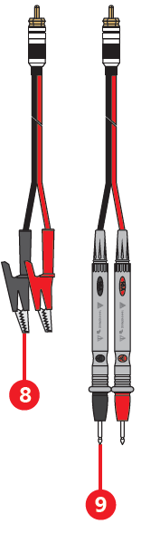
- RCA to alligator clips (red/black)
- RCA to test probes (red/black)
OPERATION INSTRUCTIONS
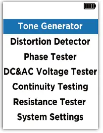
- Power On/Off: Short-press the “On/Off” button to power on and enter the main menu. If there is no operation, the device will automatically shut down after 5 minutes. Alternatively, you can long press the “On/Off” button for 2 seconds to power off.
- In the main menu, use
 the buttons to move the cursor and select different functions. Press “Enter” to enter the selected function interface, and press “Return” to return to the main menu.
 - The interfaces of different functions will display interface prompts at the top and simple usage tips at the bottom.
- The battery indicator is located in the top right corner of the screen. When the battery is low, you can charge it through the Type-C port at the bottom. The device cannot be used while charging.
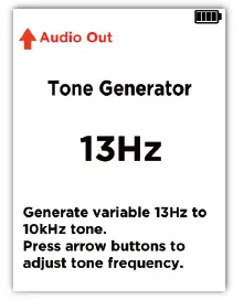
TONE GENERATOR
This function generates square wave signals of a certain frequency through the multi-functional input/output port. It can drive the speaker to produce sound and can be used to check the connection of speaker wires and verify if they correspond correctly to the harness.
- Select “Tone Generator” from the main menu and press “Enter” to enter this function interface.
- Follow the on-screen instructions to connect the RCA end of the accessory harness (you can choose between RCA to alligator clips or RCA to test probes) to the multi-functional input/out-put port, and connect the other end to the positive and negative poles of the speaker wires to be tested. The corresponding speaker will produce sound according to the output signal frequency.
- Use the buttons to adjust the output signal frequency between 13Hz and 10KHz.
- Press “Return” to return to the main menu.
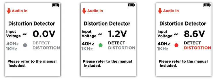
DISTORTION DETECTOR
This function helps us quickly and accurately set the gain of the amplifier to ensure that no matter how high the volume of the host is adjusted, it will not output excessive power that could damage the amplifier or speakers. To perform the test, you will need to use the test audio files stored in the accompanying USB flash drive (Track 1: 40Hz -0dB and Track 2: 1kHz -0dB).
Testing the maximum undistorted volume of the host:
- Before testing, turn off the host’s EQ, crossover settings, and set the bass and treble adjustments to 0. After the test is completed, these settings can be restored according to personal preferences.
- Select “Distortion Detector” from the main menu and press “Enter” to enter this function interface. Follow the on-screen instructions to connect the device’s multi-functional input/output port to one of the host’s audio output terminals (either directly to the RCA input port or using the accessory cable).
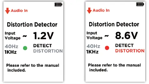
- Play the test audio Track 1: 40Hz -0dB through the host. Slowly increase the volume of the host. The screen will display “40Hz DETECT” illuminated and the distortion indicator will be green, while also displaying the detected audio voltage.
- Continue to slowly increase the volume of the host until “DISTORTION” lights up and the distortion indicator turns red. Then slowly decrease the volume until “DISTORTION” turns gray and the distortion indicator turns green again. Record the volume setting at this time.
- Switch to test audio Track 2: 1kHz -0dB. Repeat steps c-d.
- Take the average of the two recorded volume settings as the host’s maximum undistorted volume.
- Testing the maximum undistorted volume of the host connected to the amplifier:
- Before testing, turn off the host’s EQ, crossover settings, and set the bass and treble adjustments to 0. After the test is completed, these settings can be restored according to personal preferences.
- Adjust the amplifier’s volume to the minimum position; disable the amplifier’s crossover and filtering settings. If it’s a subwoofer amplifier, set the low-pass frequency to the highest position.
- Select “Distortion Detector” from the main menu and press “Enter” to enter this function interface. Follow the on-screen instructions to connect the device’s multi-functional input/output port to one of the amplifier’s audio output terminals (use the accessory cable, with the red wire connected to the positive terminal and the black wire connected to the negative terminal).
- Play the test audio Track 1: 40Hz -0dB through the host. Slowly increase the volume of the host. The screen will display “40Hz DETECT” illuminated and the distortion indicator will be green, while also displaying the detected audio voltage.
- Continue to slowly increase the volume of the host until “DISTORTION” lights up and the distortion indicator turns red. Then slowly decrease the volume until “DISTORTION” turns gray and the distortion indicator turns green again. Record the volume setting at this time.
- If it’s a full-range amplifier, switch to test audio Track 2: 1kHz -0dB. Repeat steps d-e.
- Take the average of the two recorded volume settings as the maximum undistorted volume when the host is connected to the amplifier.
Setting the amplifier’s maximum undistorted volume: - Before testing, turn off the host’s EQ, crossover settings, and set the bass and treble adjustments to 0. After the test is completed, these settings can be restored according to personal preferences. Set the host’s volume to the maximum undistorted volume determined in the previous step.
- Adjust the amplifier’s volume to the minimum position; disable the amplifier’s crossover and filtering settings. Disconnect all speakers connected to the amplifier’s output terminals. If it’s a subwoofer amplifier, set the low-pass frequency to the highest position. If there’s a bass boost knob, set it to the position typically used during normal operation.
- Select “Distortion Detector” from the main menu and press “Enter” to enter this function interface. Follow the on-screen instructions to connect the device’s multi-functional input/output port to one of the amplifier’s audio output terminals (use the accessory cable, with the red wire connected to the positive terminal and the black wire connected to the negative terminal).
- Play the test audio Track 2: 1kHz -0dB through the host (if it’s a subwoofer amplifier, play audio Track 1: 40Hz -0dB).
- Slowly increase the amplifier’s volume until “DISTORTION” lights up and the distortion indicator turns red. Then slowly decrease the volume until “DISTORTION” turns gray and the distortion indicator turns green again.
- This position represents the maximum undistorted volume of the amplifier in the current host-amplifier system.
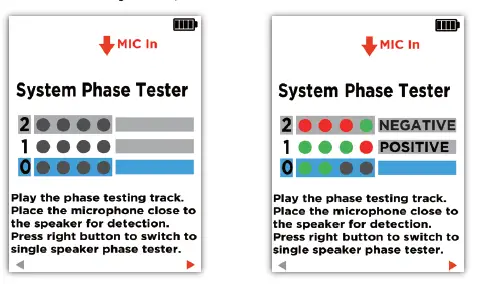
PHASE TESTER
Inconsistent phase among speakers in an audio system can lead to sound waves canceling each other out, resulting in an indistinct soundstage and a lack of stereo sensation. This function detects the phase of each speaker in the audio system and can also check the polarity of individual speaker wiring terminals. The detection should be performed in a relatively quiet environment, such as with the car doors open and the car air conditioning and other noise-generating devices turned off. Testing requires the use of the test audio file stored in the accompanying USB flash drive (Track 3: Phase test signal).
 System Phase Tester:
- After installing the audio system, play the audio Track 3: Phase test signal through the host and adjust the volume to an appropriate level.
- Select “Phase Tester” from the main menu and press “Enter” to enter the “Phase Tester in the System” interface. Follow the on-screen instructions to position the device’s front microphone receiver near and facing the front of the speaker being tested.
- The device will display the polarity of each detected signal in real-time,
 indicating positive phase,
 or negative phase). After detecting 4 valid signals, the phase of the speaker can be determined. The screen will continuously display the valid phase information obtained from the first two consecutive detections.
 - If inconsistent speaker phases are detected, change all speakers to either positive or negative phase (switch speaker positive and negative polarity connection wires or change phase settings in the DSP system).
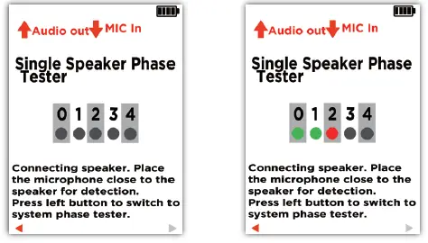
Single Speaker Phase Tester:
- In the “Phase Tester in the System” interface, press to switch to the “Single Speaker Polarity Detection” interface.
- Follow the on-screen instructions to connect both terminals of the speaker to the device’s multi-functional input/output port using the accessory cable. Position the device’s front microphone receiver near and facing the front of the speaker.
- The device will display the polarity of each detected signal in real-time , indicating positive phase, indicates negative phase). If a positive phase is detected, the terminal connected to the red wire of the accessory cable is the positive terminal of the speaker. If a negative phase is detected, the terminal connected to the black wire of the accessory cable is the positive terminal of the speaker.
DC&AC VOLTAGE TESTER
This function is used to assist in troubleshooting. DC voltage detection can measure the power supply voltage of devices in the car, with a measurement range of 32V. AC voltage detection can measure the audio signal voltage at the host and amplifier output terminals.
It is strictly prohibited to use this product to measure mains electricity!
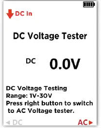
DC Voltage Detection
- Select “Voltage Detection” from the main menu and press “Enter” to enter the “DC Voltage Detection” interface.
- Follow the on-screen instructions to connect the accessory cable to the device’s multi-functional input/output port.
- Connect the red and black test probes or red and black alligator clips to the terminals to be tested, and the screen will display the measured voltage.
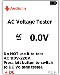
 AC Voltage Detection (Audio Signal Voltage)
- While in the “DC Voltage Detection” interface, press to switch to the “AC Voltage Detection” interface.
- Follow the on-screen instructions to connect the accessory cable to the device’s multi-functional input/output port.
- You can play audio Track 2: 1kHz -0dB through the host and adjust it to an appropriate volume. Connect the red and black test probes or red and black alligator clips to the audio output terminals of the host or amplifier, and the screen will display the measured signal voltage.
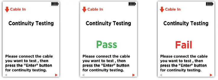
CONTINUITY TESTING
This function is used for quickly checking the continuity of wiring harnesses and RCA cables. Please do not perform measurements while the circuit is energized!
Continuity Testing:
- Select “Continuity Testing” from the main menu and press “Enter” to enter the “Continuity Testing” interface.
- Follow the on-screen instructions to connect the accessory cable to the device’s multi-functional input/output port.
- Connect the red and black test probes or red and black alligator clips to both ends of the wire to be tested. Press “Enter” to complete a test. If the connection is good, it will display “Connection Normal”; otherwise, it will display “Connection Failed”.
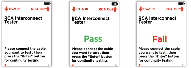
RCA Interconnect Tester:
- While in the “Continuity Testing” interface, press to switch to the “RCA Audio Cable Test” interface.
- Follow the on-screen instructions to connect one end of the RCA audio cable to the device’s multi-functional input/output port and the other end to the RCA output port.
- Press “Enter” to complete a test. If the connection is good, it will display “Connection Normal”; otherwise, it will display “Connection Failed”.
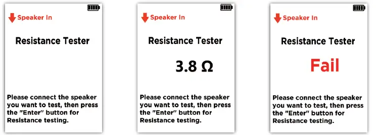
RESISTANCE TESTER
This function is used to measure the resistance of individual speakers. Before measurement, disconnect the speaker from the host or amplifier.
-
Select “resistance Tester” from the main menu and press “Enter” to enter the “resistance Tester” interface.
- Follow the on-screen instructions to connect the accessory cable to the device’s multi-functional input/output port.
- Connect the red and black test probes or red and black alligator clips to both ends of the speaker to be tested. Press “Enter” to complete a test, and the current Resistance value of the speaker will be displayed.
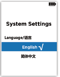
SYSTEM SETTINGS
This function allows you to set the display language.
- Select “System Settings” from the main menu and press “Enter” to enter the “System Settings” interface.
- Use the cursor to switch between “English” and” (Simplified Chinese). Press “Enter” to confirm your selection and press “Return” to return to the main menu.
Documents / Resources
 |
Auto-Connect MFAST Multi Function Audio System Tester [pdf] User Manual MFAST Multi Function Audio System Tester, MFAST, Multi Function Audio System Tester, Audio System Tester, System Tester, Tester |


