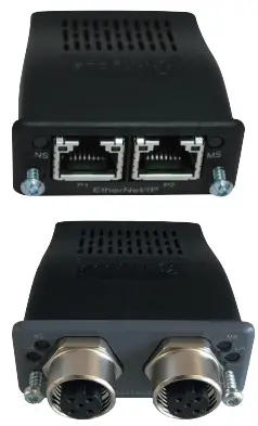
Fronius RI MOD Compact Com Module
Specifications
- Product Name: RI FB PRO/i RI MOD/i CC Ethernet/IP-2P
- Vendor: Fronius International GmbH
- Device Type: Communication adapter
- Product Code: 0320hex (800dez)
- Image Type: Standard Image
- Instance Type: Producing Instance
- Consuming Instance: Consuming Instance
- Instance Name: Fronius-FB-Pro-EtherNetIP(TM)
Product Usage Instructions
Setting the IP Address of the Bus Module
The IP address of the bus module can be set using the DIP switches on the interface:
- Set the IP address within the range of 192.168.0.xx (where xx corresponds to DIP switch positions from 1 to 63).
- DIP switch settings and corresponding IP addresses:
| DIP Switch | IP Address |
|---|---|
| OFF OFF OFF OFF OFF OFF ON | 1 |
| OFF OFF OFF OFF OFF ON OFF | 2 |
| OFF OFF OFF OFF OFF ON ON | 3 |
| ON ON ON ON ON OFF | 62 |
| ON ON ON ON ON ON | 63 |
Data Types and Signal Mapping
The product uses the following data types:
- UINT16 (Unsigned Integer) – Range: 0 to 65535
- SINT16 (Signed Integer) – Range: -32768 to 32767
Address mapping for input and output signals:
| Address | Type | Description |
|---|---|---|
| 0-7 | BIT Signal | Signal Mapping Details |
General
Safety
WARNING!
Danger from incorrect operation and work that is not carried out properly. This can result in serious personal injury and damage to property.
- All the work and functions described in this document must only be carried out by technically trained and qualified personnel.
- Read and understand this document in full.
- Read and understand all safety rules and user documentation for this equip-ment and all system components.
Connections and Displays
| 1 | TX+ |
| 2 | TX- |
| 3 | RX+ |
| 6 | RX- |
| 4,5,7, | Not normally used; to ensure- |
| 8 | re signal completeness, the |
| se pins must be Intercon- | |
| nected and, after passing | |
| through a filter circuit, must | |
| terminate at the ground | |
| conductor (PE). |
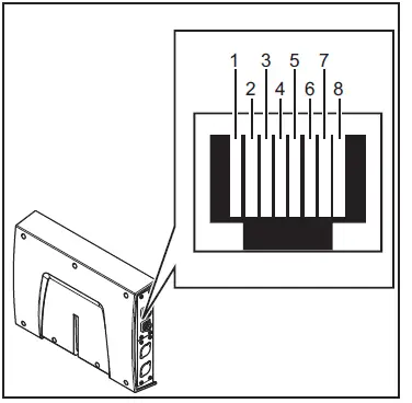
RJ45 connection
| (1) LED MS – Module status |
| Off:
No supply voltage |
| Lights up green:
Controlled by a master |
| Flashes green (once):
Master not configured or master idle |
| Lights up red:
Major error (exception state, serious fault, …) |
| Flashes red:
Correctable error |
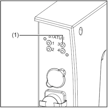
| (2) LED NS – Network status |
| Off:
No supply voltage or no IP address |
| Lights up green:
Online, one or more connections established (CIP category 1 or 3) |
| Flashes green:
Online, no connection is established |
| Lights up red:
Double IP address, serious error |
| Flashes red:
Overrun of time for one or more connections (CIP category 1 or 3) |
Data Transfer Properties
Transfer technology
- Ethernet
Medium
- When selecting the cables and plugs, the ODVA recommendation for the plan-ning and installation of EtherNet/IP systems must be observed. The EMC tests were carried out by the manufacturer with the cable IE-C5ES8VG0030M40M40-F.
Transmission speed
- 10 Mbit/s or 100 Mbit/s
Bus connection
- RJ-45 Ethernet / M12
Configuration Parameters
- In some robot control systems, it may be necessary to state the configuration parameters described here so that the bus module can communicate with the robot.
| Parameter | Value | Description |
| Vendor ID | 0534hex (1332dec) | Fronius International GmbH |
| Device Type | 000Chex (12dec) | Communication adapter |
| Product Code | 0320hex (800dec) | Fronius FB Pro Ethernet/IP-2-Port |
Product Name Fronius-FB-Pro-EtherNetIP(TM)
|
Image Type |
Instance Type |
Instance Name |
Instance Description |
Instance Number |
Size [Byt e] |
| Standard Image | Produ- coming Instance | Input Data Standard | Data from power source to robot | 100 | 40 |
|
Image Type |
Instance Type |
Instance Name |
Instance Description |
Instance Number |
Size [Byt e] |
| Con- summing Instance | Output Data Standard | Data from robot to power source | 150 | 40 | |
| Economy Image | Produ- coming Instance | Input Data Standard | Data from power source to robot | 101 | 16 |
| Con- summing Instance | Output Data Standard | Data from robot to power source | 151 | 16 |
Setting the Bus Module IP Address
Setting the Bus Module IP Address You can set the bus module IP address as follows:
- Using the DIP switch in the interface within the range defined by 192.168.0.xx (xx = DIP switch setting = 1 to 63)
- All positions are set to the OFF position at the factory. In this case, the IP address must be set on the website of the welding machine
- On the website of the welding machine (if all positions of the DIP switch are set to the OFF position)
The IP address is set using DIP switch positions 1 to 6. The configuration is carried out in binary format. This results in a configuration range of 1 to 63 in decimal format.
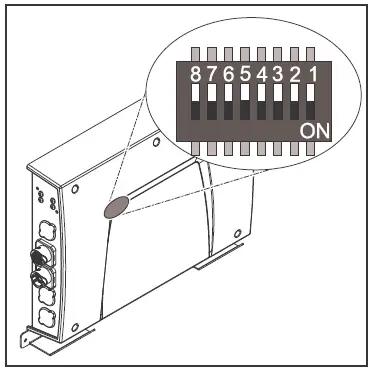
| Example for setting the IP address of the bus module using the DIP switch in the interface: | ||||||||
| Dip switch | ||||||||
| 8 | 7 | 6 | 5 | 4 | 3 | 2 | 1 | IP address |
| – | – | OFF | OFF | OFF | OFF | OFF | ON | 1 |
| – | – | OFF | OFF | OFF | OFF | ON | OFF | 2 |
| – | – | OFF | OFF | OFF | OFF | ON | ON | 3 |
| – | – | ON | ON | ON | ON | ON | OFF | 62 |
| – | – | ON | ON | ON | ON | ON | ON | 63 |
Instructions for setting the IP address on the website of the welding machine:
Note down the IP address of the welding machine used:
- On the welding machine control panel, select “Defaults”
- On the welding machine control panel, select “System”
- On the welding machine control panel, select “Information”
- Note down the displayed IP address (example: 10.5.72.13)
Access the website of the welding machine in the internet browser:
- Connect the computer to the network of the welding machine
- Enter the IP address of the welding machine in the search bar of the internet browser and confirm
- Enter the standard user name (admin) and password (admin)
- The website of the power source is displayed
Set the bus module IP address:
- On the power welding machine, select the “RI FB PRO/i” tab
- Enter the desired IP address for the interface under “Module configuration”. For example: 192.168.0.12
- Select “Set configuration”
- Select “Restart module”
- The set IP address is applied
Input and output signals
Data types
The following data types are used:
- UINT16 (Unsigned Integer)
- The whole number in the range from 0 to 65535
- SINT16 (Signed Integer)
- The whole number ranges from -32768 to 32767
Conversion examples:
- for a positive value (SINT16) e. g. desired wire speed x factor 12.3 m/min x 100 = 1230dec = 04CEhex
- for a negative value (SINT16) e. g. arc correction x factor -6.4 x 10 = -64dec = FFC0hex
Availability of input signals
The input signals listed below are available from firmware V2.0.0 of the RI FB PRO/i onwards.
Input signals (from robot to power source)
|
Address |
Signal |
Activity/data type |
Range |
Factor | Process image | ||||
|
Relative |
Absolu- te | Standard | Economy | ||||||
| WORD | BYTE | BIT |
BIT |
||||||
|
0 |
0 |
0 | 0 | Welding Start | Increa- sing |
ü |
ü |
||
| 1 | 1 | Robot ready | High | ||||||
| 2 | 2 | Working mode Bit 0 | High |
See table Value Range for Working Mode on page 35 |
|||||
| 3 | 3 | Working mode Bit 1 | High | ||||||
| 4 | 4 | Working mode Bit 2 | High | ||||||
| 5 | 5 | Working mode Bit 3 | High | ||||||
| 6 | 6 | Working mode Bit 4 | High | ||||||
| 7 | 7 | — | |||||||
|
1 |
0 | 8 | Gas on | Increa- sing | |||||
| 1 | 9 | Wire forward | Increa- sing | ||||||
| 2 | 10 | Wire backward | Increa- sing | ||||||
| 3 | 11 | Error quit | Increa- sing | ||||||
| 4 | 12 | Touch sensing | High | ||||||
| 5 | 13 | Torch blow out | Increa- sing | ||||||
| 6 | 14 | Processing selection Bit 0 | High | See table Value range Process li- ne selection on page 36 | |||||
|
7 |
15 |
Processing selection Bit 1 |
High |
||||||
|
Address |
Signal |
Activity/data type |
Range |
Factor | Process image | ||||
|
Relative |
Absolu- te | Standard | Economy | ||||||
| WORD | BYTE | BIT |
BIT |
||||||
|
1 |
2 |
0 | 16 | Welding simulation | High |
ü |
ü |
||
|
1 |
17 |
Welding process MIG/MAG: 1)
Synchro pulse on |
High |
||||||
| Welding process WIG: 2)
TAC on |
High |
||||||||
|
2 |
18 |
Welding process WIG: 2)
Cap shaping |
High |
||||||
| 3 | 19 | — | |||||||
| 4 | 20 | — | |||||||
| 5 | 21 | Booster manual | High | ||||||
| 6 | 22 | Wire brake on | High | ||||||
| 7 | 23 | Torchbody Xchange | High | ||||||
|
3 |
0 | 24 | — | ||||||
| 1 | 25 | Teach mode | High | ||||||
| 2 | 26 | — | |||||||
| 3 | 27 | — | |||||||
| 4 | 28 | — | |||||||
| 5 | 29 | Wire since start | Increa- sing | ||||||
| 6 | 30 | Wire sense break | Increa- sing | ||||||
| 7 | 31 | — | |||||||
|
Address |
Signal |
Activity/data type |
Range |
Factor | Process image | ||||
|
Relative |
Absolu- te | Standard | Economy | ||||||
| WORD | BYTE | BIT |
BIT |
||||||
|
2 |
4 |
0 | 32 | TWIN mode Bit 0 | High | See table Value Range for TWIN Mode on page 36 |
ü |
ü |
|
|
1 |
33 |
TWIN mode Bit 1 |
High |
||||||
| 2 | 34 | — | |||||||
| 3 | 35 | — | |||||||
| 4 | 36 | — | |||||||
|
5 |
37 |
Documentation mode |
High |
See table Value Range for Docu- mentation Mode on page 36 | |||||
| 6 | 38 | — | |||||||
| 7 | 39 | — | |||||||
|
5 |
0 | 40 | — | ||||||
| 1 | 41 | — | |||||||
| 2 | 42 | — | |||||||
| 3 | 43 | — | |||||||
| 4 | 44 | — | |||||||
| 5 | 45 | — | |||||||
| 6 | 46 | — | |||||||
| 7 | 47 | Disable process-controlled correction | High | ||||||
|
Address |
Signal |
Activity/data type |
Range |
Factor | Process image | ||||
|
Relative |
Absolu- te | Standard | Economy | ||||||
| WORD | BYTE | BIT |
BIT |
||||||
|
3 |
6 |
0 | 48 | — |
ü |
ü |
|||
| 1 | 49 | — | |||||||
| 2 | 50 | — | |||||||
| 3 | 51 | — | |||||||
| 4 | 52 | — | |||||||
| 5 | 53 | — | |||||||
| 6 | 54 | — | |||||||
| 7 | 55 | — | |||||||
|
7 |
0 | 56 | ExtInput1 => OPT_Output 1 | High | |||||
| 1 | 57 | ExtInput2 => OPT_Output 2 | High | ||||||
| 2 | 58 | ExtInput3 => OPT_Output 3 | High | ||||||
| 3 | 59 | ExtInput4 => OPT_Output 4 | High | ||||||
| 4 | 60 | ExtInput5 => OPT_Output 5 | High | ||||||
| 5 | 61 | ExtInput6 => OPT_Output 6 | High | ||||||
| 6 | 62 | ExtInput7 => OPT_Output 7 | High | ||||||
| 7 | 63 | ExtInput8 => OPT_Output 8 | High | ||||||
| 4 | 8-
9 |
0–7 | 64–79 | Welding characteristic- / Job number | UINT16 | 0 to 1000 | 1 | ü | ü |
|
5 |
10 – 11 |
0-7 |
80-95 |
Welding process MIG/MAG: 1)
Constant Wire:
Wire feed speed command value |
SINT16 |
-327,68 to 327,67 [m/min] |
100 |
ü |
ü |
| Welding process WIG: 2)
Main- / Hotwire current command value |
UINT16 |
0 to 6553,5 [A] |
10 |
||||||
| For job-mode:
Power correction |
SINT16 |
-20,00 to
20,00 [%] |
100
|
||||||
|
Address |
Signal |
Activity/data type |
Range |
Factor | Process image | ||||
|
Relative |
Absolu- te | Standard | Economy | ||||||
| WORD | BYTE | BIT |
BIT |
||||||
|
6 |
12 – 13 |
0-7 |
96-111 |
Welding process MIG/MAG: 1)
Arclength correction |
SINT16 |
-10,0 to
10,0 [Schritte] |
10 |
ü |
ü |
| Welding process
MIG/MAG Standard-Manuel:
Welding voltage |
UINT16 |
0,0 to
6553,5 [V] |
10 |
||||||
| Welding process WIG: 2)
Wire feed speed command value |
SINT16 |
-327,68 to 327,67 [m/min] |
100 |
||||||
| For job-mode:
Arclength correction |
SINT16 |
-10,0 to
10,0 [Schritte] |
10 |
||||||
| Welding process Constant Wire:
Hotwire current |
UINT16 |
0,0 to
6553,5 [A] |
10 |
||||||
|
7 |
14 – 15 |
0-7 |
112-127 |
Welding process MIG/MAG: 1)
Pulse-/dynamic correction |
SINT16 |
-10,0 to
10,0 [steps] |
10 |
ü |
ü |
| Welding process
MIG/MAG Standard-Manuel:
Dynamic |
UINT16 |
0,0 to
10,0 [steps] |
10 |
||||||
| Welding process WIG: 2)
Wire correction |
SINT16 |
-10,0 to
10,0 [steps] |
10 |
||||||
|
8 |
16 – 17 |
0-7 |
128-143 |
Welding process MIG/MAG: 1)
Wire retract correction |
UINT16 |
0,0 to
10,0 [steps] |
10 |
ü |
|
| Welding process WIG: 2)
Wire retract end |
UINT16 |
OFF, 1 to
50 [mm] |
1 |
||||||
|
9 |
18
– 19 |
0-7 |
144-159 |
Welding speed |
UINT16 |
0,0 to
1000,0 [cm/min] |
10 |
ü |
|
|
Address |
Signal |
Activity/data type |
Range |
Factor | Process image | ||||
|
Relative |
Absolu- te | Standard | Economy | ||||||
| WORD | BYTE | BIT |
BIT |
||||||
|
10 |
20 – 21 |
0-7 |
160-175 |
Process controlled correction |
See table Value range for Process controlled correction on page 36 |
ü |
|||
|
11 |
22
– 23 |
0-7 |
176-191 |
Welding process WIG: 2)
Wire positioning start |
ü |
||||
|
12 |
24
– 25 |
0-7 |
192-207 |
— |
ü |
||||
|
13 |
26
– 27 |
0-7 |
208-223 |
— |
ü |
||||
|
14 |
28
– 29 |
0-7 |
224-239 |
— |
ü |
||||
|
15 |
30
– 31 |
0-7 |
240-255 |
Wire forward / backward length |
UINT16 |
OFF / 1 to 65535 [mm] |
1 |
ü |
|
|
16 |
32
– 33 |
0-7 |
256-271 |
Wire sense edge detection |
UINT16 |
OFF / 0,5
to 20,0 [mm] |
10 |
ü |
|
|
17 |
34
– 35 |
0-7 |
272-287 |
— |
ü |
||||
|
18 |
36
– 37 |
0-7 |
288-303 |
— |
ü |
||||
|
19 |
38
– 39 |
0-7 |
304-319 |
Seam number |
UINT16 |
0 to
65535 |
1 |
ü |
|
- MIG/MAG Puls-Synergic, MIG/MAG Standard-Synergic, MIG/MAG Stan- dard-Manuel, MIG/MAG PMC, MIG/MAG, LSC
- WIG cold wire, WIG hotwire
Value Range for Working Mode
| Bit 4 | Bit 3 | Bit 2 | Bit 1 | Bit 0 | Description |
| 0 | 0 | 0 | 0 | 0 | Internal parameter selection |
| 0 | 0 | 0 | 0 | 1 | Special 2-step mode characteristics |
| 0 | 0 | 0 | 1 | 0 | Job mode |
| Bit 4 | Bit 3 | Bit 2 | Bit 1 | Bit 0 | Description |
| 0 | 1 | 0 | 0 | 0 | 2-step mode characteristics |
| 0 | 1 | 0 | 0 | 1 | 2-step MIG/MAG standard manual |
| 1 | 0 | 0 | 0 | 0 | Idle Mode |
| 1 | 0 | 0 | 0 | 1 | Stop coolant pump |
| 1 | 1 | 0 | 0 | 1 | R/L-Measurement |
Value range for operating mode
Value Range for Documentation Mode
| Bit 0 | Description |
| 0 | Seam number of welding machine (internal) |
| 1 | Seam number of robots (Word 19) |
The value range for documentation mode
The value range for Process control-led correction
|
Process |
Signal |
Activity/data type |
Value range configuration range |
Unit |
Factor |
|
PMC |
Arc length stabilizer |
SINT16 |
-327.8 to +327.7
0.0 to +5.0 |
Volts |
10 |
The value range for documentation mode
The value range for Process control-led correction
|
Process |
Signal |
Activity/data type |
Value range configuration range |
Unit |
Factor |
|
PMC |
Arc length stabilizer |
SINT16 |
-327.8 to +327.7
0.0 to +5.0 |
Volts |
10 |
The value range for process-dependent correction
Value range Process line selection
| Bit 1 | Bit 0 | Description |
| 0 | 0 | Process line 1 (default) |
| 0 | 1 | Process line 2 |
| 1 | 0 | Process line 3 |
| 1 | 1 | Reserved |
Value range for process line selection
Value Range for TWIN Mode
| Bit 1 | Bit 0 | Description |
| 0 | 0 | TWIN Single mode |
| 0 | 1 | TWIN Lead mode |
| 1 | 0 | TWIN Trail mode |
| 1 | 1 | Reserved |
The value range for the TWIN mode
Availability of the output signals
The output signals listed below are available from firmware V2.0.0 of the RI FB PRO/i onwards.
Output Signals (from Power Source to Robot)
|
Address |
Signal |
Activity/data type |
Range |
Factor |
Process image | ||||
| relative | absolute | Standard | Economy | ||||||
| WORD | BYTE | BIT |
BIT |
||||||
|
0 |
0 |
0 | 0 | Heartbeat Powersource | High/Low | 1 Hz |
ü |
ü |
|
| 1 | 1 | Power source ready | High | ||||||
| 2 | 2 | Warning | High | ||||||
| 3 | 3 | Process active | High | ||||||
| 4 | 4 | Current flow | High | ||||||
| 5 | 5 | Arc stable- / touch signal | High | ||||||
| 6 | 6 | Main current signal | High | ||||||
| 7 | 7 | Touch signal | High | ||||||
|
1 |
0 |
8 |
Collision box active |
High |
0 = collision- on or cable break | ||||
| 1 | 9 | Robot Motion Release | High | ||||||
| 2 | 10 | Wire stick workpiece | High | ||||||
| 3 | 11 | — | |||||||
| 4 | 12 | Short circuit contact tip | High | ||||||
| 5 | 13 | Parameter selection in- eternally | High | ||||||
| 6 | 14 | Characteristic number valid | High | ||||||
| 7 | 15 | Torch body gripped | High | ||||||
|
Address |
Signal |
Activity/data type |
Range |
Factor |
Process image | ||||
| relative | absolute | Standard | Economy | ||||||
| WORD | BYTE | BIT |
BIT |
||||||
|
1 |
2 |
0 | 16 | Command value out of range | High |
ü |
ü |
||
| 1 | 17 | Correction out of range | High | ||||||
| 2 | 18 | — | |||||||
| 3 | 19 | Limitsignal | High | ||||||
| 4 | 20 | — | |||||||
| 5 | 21 | — | |||||||
| 6 | 22 | Main supply status | Low | ||||||
| 7 | 23 | — | |||||||
|
3 |
0 | 24 | Sensor status 1 | High |
See table Assign- ment of Sensor Sta- uses 1–4 on page 40 |
||||
| 1 | 25 | Sensor status 2 | High | ||||||
| 2 | 26 | Sensor status 3 | High | ||||||
| 3 | 27 | Sensor status 4 | High | ||||||
| 4 | 28 | — | |||||||
| 5 | 29 | — | |||||||
| 6 | 30 | — | |||||||
| 7 | 31 | — | |||||||
|
2 |
4 |
0 | 32 | — |
ü |
ü |
|||
| 1 | 33 | — | |||||||
| 2 | 34 | — | |||||||
| 3 | 35 | Safety status Bit 0 | High | See table Value ran- ge Safety status on page 41 | |||||
| 4 | 36 | Safety status Bit 1 | High | ||||||
| 5 | 37 | — | |||||||
| 6 | 38 | Notification | High | ||||||
| 7 | 39 | System not ready | High | ||||||
|
5 |
0 | 40 | — | ||||||
| 1 | 41 | — | |||||||
| 2 | 42 | — | |||||||
| 3 | 43 | — | |||||||
| 4 | 44 | — | |||||||
| 5 | 45 | — | |||||||
| 6 | 46 | — | |||||||
| 7 | 47 | — | |||||||
|
Address |
Signal |
Activity/data type |
Range |
Factor |
Process image | ||||
| relative | absolute | Standard | Economy | ||||||
| WORD | BYTE | BIT |
BIT |
||||||
|
3 |
6 |
0 | 48 | Process Bit 0 | High |
See table Value Range for Process Bit on page 41 |
ü |
ü |
|
| 1 | 49 | Process Bit 1 | High | ||||||
| 2 | 50 | Process Bit 2 | High | ||||||
| 3 | 51 | Process Bit 3 | High | ||||||
| 4 | 52 | Process Bit 4 | High | ||||||
| 5 | 53 | — | |||||||
| 6 | 54 | Touch signal gas nozzle | High | ||||||
| 7 | 55 | TWIN synchronization active | High | ||||||
|
7 |
0 | 56 | ExtOutput1 <= OPT_In- put1 | High | |||||
| 1 | 57 | ExtOutput2 <= OPT_In- put2 | High | ||||||
| 2 | 58 | ExtOutput3 <= OPT_In- put3 | High | ||||||
| 3 | 59 | ExtOutput4 <= OPT_In- put4 | High | ||||||
| 4 | 60 | ExtOutput5 <= OPT_In- put5 | High | ||||||
| 5 | 61 | ExtOutput6 <= OPT_In- put6 | High | ||||||
| 6 | 62 | ExtOutput7 <= OPT_In- put7 | High | ||||||
| 7 | 63 | ExtOutput8 <= OPT_In- put8 | High | ||||||
| 4 | 8-
9 |
0-7 | 64-79 | Welding voltage | UINT16 | 0.0 to
655.35 [V] |
100 | ü | ü |
|
5 |
10
– 11 |
0-7 |
80-95 |
Welding current |
UINT16 |
0.0 to 6553.5 [A] |
10 |
ü |
ü |
|
6 |
12
– 13 |
0-7 |
96-111 |
Wire feed speed |
SINT16 |
-327.68 to
327.67 [m/ min] |
100 |
ü |
ü |
|
7 |
14
– 15 |
0-7 |
112-127 |
Actual real value for seam tracking |
UINT16 |
0 to
6.5535 |
10000 |
ü |
ü |
|
8 |
16
– 17 |
0-7 |
128-143 |
Error number |
UINT16 |
0 to
65535 |
1 |
ü |
|
|
9 |
18
– 19 |
0-7 |
144-159 |
Warning number |
UINT16 |
0 to
65535 |
1 |
ü |
|
|
Address |
Signal |
Activity/data type |
Range |
Factor |
Process image | ||||
| relative | absolute | Standard | Economy | ||||||
| WORD | BYTE | BIT |
BIT |
||||||
|
10 |
20
– 21 |
0-7 |
160-175 |
Motor current M1 |
SINT16 |
-327.68 to
327.67 [A] |
100 |
ü |
|
|
11 |
22
– 23 |
0-7 |
176-191 |
Motor current M2 |
SINT16 |
-327.68 to
327.67 [A] |
100 |
ü |
|
|
12 |
24
– 25 |
0-7 |
192-207 |
Motor current M3 |
SINT16 |
-327.68 to
327.67 [A] |
100 |
ü |
|
|
13 |
26
– 27 |
0-7 |
208-223 |
— |
ü |
||||
|
14 |
28
– 29 |
0-7 |
224-239 |
— |
ü |
||||
|
15 |
30
– 31 |
0-7 |
240-255 |
— |
ü |
||||
|
16 |
32
– 33 |
0-7 |
256-271 |
Wire position |
SINT16 |
-327.68 to
327.67 [mm] |
100 |
ü |
|
|
17 |
34
– 35 |
0-7 |
272-287 |
— |
ü |
||||
|
18 |
36
– 37 |
0-7 |
288-303 |
— |
ü |
||||
|
19 |
38
– 39 |
0-7 |
304-319 |
— |
ü |
||||
Assignment of Sensor Statuses 1–4
| Signal | Description |
| Sensor status 1 | OPT/i WF R wire end (4,100,869) |
| Sensor status 2 | OPT/i WF R wire drum (4,100,879) |
| Sensor status 3 | OPT/i WF R ring sensor (4,100,878) |
| Sensor status 4 | Wire buffer set CMT TPS/I (4,001,763) |
Assignment of sensor statuses
Value range Safety status
| Bit 1 | Bit 0 | Description |
| 0 | 0 | Reserve |
| 0 | 1 | Hold |
| 1 | 0 | Stop |
| 1 | 1 | Not installed / active |
Value Range for Process Bit
| Bit 4 | Bit 3 | Bit 2 | Bit 1 | Bit 0 | Description |
| 0 | 0 | 0 | 0 | 0 | No internal parameter selection or process |
| 0 | 0 | 0 | 0 | 1 | MIG/MAG pulse synergic |
| 0 | 0 | 0 | 1 | 0 | MIG/MAG standard synergic |
| 0 | 0 | 0 | 1 | 1 | MIG/MAG PMC |
| 0 | 0 | 1 | 0 | 0 | MIG/MAG LSC |
| 0 | 0 | 1 | 0 | 1 | MIG/MAG standard manual |
| 0 | 0 | 1 | 1 | 0 | Electrode |
| 0 | 0 | 1 | 1 | 1 | TIG |
| 0 | 1 | 0 | 0 | 0 | CMT |
| 0 | 1 | 0 | 0 | 1 | Constantine |
| 0 | 1 | 0 | 1 | 0 | ColdWire |
| 0 | 1 | 0 | 1 | 1 | DynamicWire |
Value Range for Process Bit
Value Range for Function Status
| Bit 1 | Bit 0 | Description |
| 0 | 0 | Inactive |
| 0 | 1 | Idle |
| 1 | 0 | Finished |
| 1 | 1 | Error |
The value range for function status

- spareparts.fronius.com
- At www.fronius.com/contact you will find the contact details of all Fronius subsidiaries and Sales & Service Partners.Frequently Asked Questions
How do I troubleshoot LED status indications?
If the LED MS is lit red, it indicates a main error. If it blinks red, it signifies a fixable error. For LED NS, a red light could indicate a double IP address or a severe network error.
What are the default configuration parameters for the bus module?
The default configuration parameters include Vendor ID: 0534hex, Device Type: Communication adapter, Product Code: 0320hex, Product Name: Fronius FB Pro Ethernet/IP-2-Port.
Documents / Resources
 |
Fronius RI MOD Compact Com Module [pdf] Instruction Manual RI MOD Compact Com Module, RI MOD, Compact Com Module, Com Module, Module |


