Danfoss ECA 71 MODBUS Communication Module Instruction Manual

ECA 71 protocol for the ECL Comfort 200/300 series
1. Introduction
1.1 How to use these instructions
Software and documentation for ECA 71 can be downloaded from http://heating.danfoss.com.
Safety Note
To avoid injury of persons and damages to the device, it is absolutely necessary to read and observe these instructions carefully.
The warning sign is used to emphasize special conditions that should be taken into consideration.
This symbol indicates that this particular piece of information should be read with special attention.
1.2 About the ECA 71
The ECA 71 MODBUS communication module makes it possible to establish a MODBUS network with standard network components. Via a SCADA system (OPC Client) and the Danfoss OPC server it is possible to control the controllers in the ECL Comfort in the 200/300 series remotely.
ECA 71 can be used for all application cards in the ECL Comfort 200 series as well as in the 300 series.
The ECA 71 with proprietary protocol for ECL Comfort is based on MODBUS®.
Accessible parameters (card dependent):
- Sensor values
- References and desired values
- Manual override
- Output status
- Mode indicators and status
- Heat curve and parallel displacement
- Flow and return temperature limitations
- Schedules
- Heat meter data (only in ECL Comfort 300 as of version 1.10 and only if ECA 73 is mounted)
1.3 Compatibility
Optional ECA modules:
The ECA 71 is compatible with ECA 60-63, ECA 73, ECA 80, ECA 83, ECA 86 and ECA 88.
Max. 2 ECA modules can be connected.
ECL Comfort:
ECL Comfort 200 series
- As of ECL Comfort 200 version 1.09 ECA 71 is compatible, but an additional address tool is required. The address tool can be downloaded from http://heating.danfoss.com.
ECL Comfort 300 series
- The ECA 71 is fully compatible with ECL Comfort 300 as of version 1.10 (also known as ECL Comfort 300S) and there is no need for an additional address tool.
- ECL Comfort 300 as of version 1.08 is compatible, but an additional address tool is required.
- All versions of ECL Comfort 301 and 302 are compatible, but an additional address tool is required.
Only ECL Comfort 300 as of version 1.10 can setup the address used in the ECA 71 module. All other ECL Comfort controllers will require an address tool to set up the address.
Only ECL Comfort 300 as of version 1.10 can handle the heat meter data from the ECA 73 module.
2. Configuration
2.1 Network description
The network used for this module is conditionally compliant (implementation class = basic) with the MODBUS over serial line two-wire RS-485 interface. The module uses the RTU transmission mode. Devices are connected directly to the network, i.e.
daisy chained. The network uses line polarization and line termination at both ends.
These guidelines depend on the environmental conditions and the physical network characteristics:
- Maximum cable length of 1200 metres without repeater
- 32 devices pr. master / repeater (a repeater counts as a device)
The modules uses an auto baud rate scheme that depends on the byte error ratio. If the error ratio exceeds a limit, the baud rate is changed. This means that all devices in the network must use the same communication settings, i.e multiple communication settings are not allowed. The module can operate with either 19200 (default) or 38400 baud network baud rate, 1 start bit, 8 data bits, even parity and one stop bit (11 bits). The valid address range is 1 – 247.
For specific details, please consult the specifications
- Modbus Application Protocol V1.1a.
- MODBUS over Serial Line, Specification & Implementation guide V1.0 both of which can be found on http://www.modbus.org/

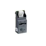
2.2 Mounting and wiring of the ECA 71


2.3 Add devices to the network
When devices are added to the network, the master must be informed. In case of an OPC Server, this information is sent by means of the Configurator. Before adding a device to the network, it is advisable set the address. The address must be unique in the network. It is recommended to maintain a map with description of device placement and their address.
2.3.1 Setup of addresses in the ECL Comfort 200/300/301
ECL Comfort 300 as of version 1.10:
- Go to line 199 (circuit I) on the grey side of the ECL Card.
- Hold the arrow down button for 5 seconds, parameter line A1 will appear (A2 and A3 are only available for ECA 73).
- The address menu is displayed (ECL Comfort 300 as of version 1.10 only)
- Choose an available address in the network (address 1-247)
Each ECL Comfort controller in the subnet must have a unique address.
ECL Comfort 200 all versions:
ECL Comfort 300 older versions (prior to 1.10):
ECL Comfort 301 all versions:
For all these ECL Comfort controllers, PC software is required for setting and reading the controller address in ECL Comfort. This software, the ECL Comfort Address Tool (ECAT), is downloadable from
http://heating.danfoss.com
System requirements:
The software is able to run under the following operating systems:
- Windows NT / XP / 2000.
PC requirements:
- Min. Pentium CPU
- Min. 5 MB free hard disk space
- Min. one free COM port for connection to the ECL Comfort controller
- A cable from the COM port for connection to the ECL Comfort controller front communication slot. This cable is available on stock (code no. 087B1162).
ECL Comfort Address Tool (ECAT):
- Download the software and run the le: ECAT.exe
- Choose the COM port into which the cable is connected
- Select a free address in the network. Please note that this tool cannot detect whether the same address is used more than once in an ECL Comfort controller
- Press ‘Write’
- To verify that the address is correct, press ‘Read’
- The button ‘Blink’ can be used to verify the connection to the controller. If ‘Blink’ is pressed, the controller starts blinking (press any button of the controller to stop the blinking again).

Address rules
General guideline of the address rules used in the SCADA module:
- An address can only be used once per network
- Valid address range 1 – 247
- The module uses the current or last known address
a. Valid address in the ECL Comfort controller (set by the ECL Comfort Address Tool or directly in the ECL Comfort 300 as of version 1.10)
b. The last used valid address
c. If no valid address has been obtained, the module address is invalid
ECL Comfort 200 and ECL Comfort 300 older versions (prior to 1.10):
Any ECA module mounted inside the ECL Comfort controller must be removed before the address can be set. If the mounted
ECA module is not removed before the address is set, the address setup will fail.
ECL Comfort 300 as of version 1.10 and ECL Comfort 301/ ECL Comfort 302:
No issues
3. General parameter description
3.1 Parameter naming
The parameters are divided into some functional sections, the main parts being the control parameter and schedule parameters.
The complete parameter list can be found in the appendix.
All parameters correspond to the MODBUS term “holding register” (or “input register” when read-only). All parameters are therefore read/write accessed as one (or more) holding/input registers independently of data type.
3.2 Control parameters
The user interface parameters are located in the address range 11000 – 13999. The 1000th decimal indicates the ECL Comfort circuit number, i.e. 11xxx is circuit I, 12xxx is circuit II and 13xxx is circuit III.
The parameters are named (numbered) in accordance with their name in the ECL Comfort. A complete list of the parameters can be found in the appendix.
3.3 Schedules
The ECL Comfort divides the schedules into 7 days (1–7), each consisting of 48 x 30-minute periods.
The week schedule in circuit III has only one day. A maximum of 3 comfort periods can be set for each day.
Rules for schedule adjustment
- The periods must be entered in chronological order, i.e. P1 … P2 … P3.
- Start and stop values must be in the range 0, 30, 100, 130, 200, 230, …, 2300, 2330, 2400.
- Start values must be before stop values if the period is active.
- When a stop period is written to zero, the period is automatically deleted.
- When a start period is written dierent from zero, a period is automatically added.
3.4 Mode and status
The mode and status parameters are located within the address range 4201 – 4213. The mode can be used to control the ECL Comfort mode. The status indicates the current ECL Comfort status.
If one circuit is set to manual mode, it applies to all circuits (i.e. the controller is in manual mode).
When the mode is changed from manual to another mode in one circuit, it also applies to all circuits in the controller. The controller automatically reverts to the previous mode if the information is available. If not (power failure / restart), the controller
will revert to the default mode of all circuits which is scheduled operation.
If standby mode is chosen, the status will be indicated as setback.

3.5 Time and date
The time and date parameters are located in the address range 64045 – 64049.
When adjusting the date it is necessary to set a valid date. Example: If the date is 30/3 and must be set to 28/2, it is necessary to change the day rst before changing the month.
3.6 Heat meter data
When an ECA 73 with heat meters (only when connected by M-Bus) is installed, it is possible to read the following values*.
- Actual flow
- Accumulated volume
- Actual power
- Accumulated energy
- Flow temperature
- Return temperature
For detailed information please consult the ECA 73 instructions and the appendix.
* Not all heat meters supports these values
3.7 Special parameters
The special parameters include information about types and versions. The parameters can be found in the parameter list in the appendix. Only the ones with a special encoding/decoding are described here.
Device version
Parameter 2003 holds the device version. The number is based on the ECL Comfort application version N.nn, encoded 256*N + nn.
ECL Comfort application
Parameter 2108 holds the ECL Comfort application. The 2 last digits indicate the application number, and the first digit(s) the application letter.

4 Good behaviour in designing a district heating MODBUS network
In this chapter some basic design recommendations are listed. These recommendations are based on communication in heating systems. This chapter is built as an example of a network design. The example can vary from a specic application. The typical requirement in heating systems is to get access to a number of similar components and to be able to make a few adjustments.
The illustrated performance levels might decrease in real systems.
In general it can be said that the network master controls the performance of the network.
4.1 Considerations before implementing communication
It is very important to be realistic when network and performance are specified. Some considerations have to be made in order to secure that important information is not blocked because of a frequent update of trivial information. Keep in mind that heating systems typically have long time constants, and hence can be polled less frequent.
4.2 Basic needs for information in SCADA systems
The ECL Comfort controller can support a network with some pieces of information concerning a heating system. It might be a good idea to consider how to split up the trac that these dierent information types generate.
- Alarm handling:
Values that are used to generate alarm conditions in the SCADA system. - Error handling:
In all networks errors will occur, error means time out, check of sum error, retransmission and extra trafic generated. The errors might be caused by EMC or other conditions, and it is important to reserve some bandwidth for error handling. - Data logging:
Logging of temperature etc. in a database is a function which typically is non-critical in a heating system. This function must normally run all the time “in the background”. It is not recommended to include parameters such as set-points and other parameters that require user interaction to change. - Online communication:
This is a direct communication with a single controller. When a controller is chosen (e.g. service picture in a SCADA system) the traffic to this single controller is increased. Parameter values can be polled frequently in order to give the user fast response. When the online communication is no longer needed (e.g. leaving the service picture in a SCADA system), the traffic must be set back to the normal level. - Other devices:
Do not forget to reserve bandwidth for devices from other manufacturers and future devices. Heat meters, pressure sensors, and other devices have to share the network capacity.
The level for different kinds of communication types must be considered (an example is given in figure 4.2a).

4.3 Final number of nodes in the network
At start-up the network has to be designed with due consideration to the final number of nodes and the network traffic in the network.
A network with a few controllers connected might run without any bandwidth problems at all. When the network is increased, however, bandwidth problems might occur in the network. To solve such problems, the amount of traffic has to be decreased in all controllers, or extra bandwidth can be implemented.
4.4 Parallel network
If a large number of controllers are used in a limited area with a limited length of the communication cable, parallel network might be a way to generate more bandwidth.
If the master is located in the middle of the network, the network can easily be split-up into two and the bandwidth can be doubled.
4.5 Bandwidth considerations
The ECA 71 is based on a command/query and response, meaning that the SCADA system sends a command/query and the ECA 71 responses to this. Do not attempt to send new commands before the ECA 71 has send the latest response or the timeout expires.
In a MODBUS network it is not possible to send commands/queries to different devices at the same time (except broadcast). One command/query – response must be completed before the next can be started. It is necessary to think about the roundtrip time
when designing the network. Larger networks will inherently have larger roundtrip times.
If multiple devices must have the same information, it is possible to use the broadcast address 0. Broadcast can only be used when no response is necessary, i.e. by a write command.
4.6 Update rate from the ECL Comfort controller
Values in the module are buffered values. The value update times depend on the application.
The following is a rough guideline:

These update times indicate how often it is reasonable to read values from the different categories
4.7 Minimize the copy of data in the network
Minimize the number of copied data. Adjust the poll time in the system to the actual need and the data update rate. It makes little sense to poll time and date every second when they only are updated once or twice every minute from the ECL Comfort controller.
4.8 Network layouts
The network must always be configured as a daisy chained network, see the three examples from a very simple network to more complex networks below.
Fig. 4.8a illustrates how termination and line polarization must be added. For specific details, consult the MODBUS specifications.

The network should not be configured as shown below:

5. Protocol
The ECA 71 module is a MODBUS compliant device. The module supports a number of public function codes. The MODBUS application data unit (ADU) is limited to 50 bytes.
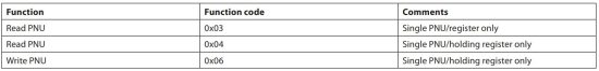
Supported public function codes
03 (0x03) Read Holding Registers
04 (0x04) Read Input Registers
06 (0x06) Write Single Register
5.1 Function codes
5.1.1 Function codes overview
5.1.2 MODBUS/ECA 71 messages
5.1.2.1 Read read-only parameter (0x03)
This function is used to read the value of an ECL Comfort read-only parameter number. Values are always returned as integer values and must be scaled according to the parameter definition.
Requesting a quantity of more than 17 parameters in sequence gives an error response. Requesting non-existing parameter number(s) will give an error response.
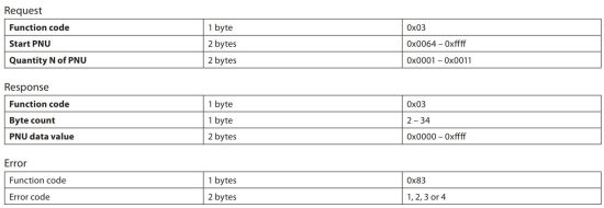
The request/response is MODBUS compliant when reading a sequence of parameters (Read input register).
5.1.2.2 Read parameters (0x04)
This function is used to read the value of an ECL Comfort parameter number. Values are always returned as integer values and must be scaled according to the parameter denition.
Requesting a quantity of more than 17 parameters gives an error response. Requesting non-existing parameter number(s) will give an error response.

5.1.2.3 Write parameter number (0x06)
This function is used to write a new setting value to an ECL Comfort parameter number. Values must be written as integer values and must be scaled according to the parameter definition.
Attempts to write a value outside the valid range will give an error response. The minimum and maximum values must be obtained from the instructions for ECL Comport controller.

5.2 Broadcasts
The modules support MODBUS broadcast messages (unit address = 0).
Command/function where a broadcast is usable
- write ECL parameter (0x06)
5.3 Error codes
For specific details, please consult the specications
- Modbus Application Protocol V1.1a.
- MODBUS over Serial Line, Specication & Implementation guide V1.0 both of which can be found on http://www.modbus.org/
6. Dismounting
![]() Disposal instruction:
Disposal instruction:
This product should be dismantled and its components sorted, if possible, in various groups before recycling or disposal.
Always follow the local disposal regulations.
Appendix
Parameter list


Danfoss can accept no responsibility for possible errors in catalogues, brochures and other printed material. Danfoss reserves the right to alter its products without notice. This also applies to products already on order provided that such alterations can be made without subsequential changes being necessary in specications already agreed.
All trademarks in this material are property of the respective companies. Danfoss and the Danfoss logotype are trademarks of Danfoss A/S. All rights reserved.
VI.KP.O2.02 © Danfoss 02/2008
Read More About This Manual & Download PDF:
Documents / Resources
 |
Danfoss ECA 71 MODBUS Communication Module [pdf] Instruction Manual 200, 300, 301, ECA 71 MODBUS Communication Module, ECA 71, MODBUS Communication Module, Communication Module, Module |