Danfoss Compliant EMD Speed Direction Function Block
Specifications
- Product Name: PLUS+1 Compliant EMD Speed Sensor Direction Function Block
- Output: RPM and directional signals
- Input Range:
- Speed (Spd): 1,250 to 10,000,000
- Direction (Dir In): 0 to 5,250 volts
Product Usage Instructions
Controller Configurations
The EMD_SPD_DIR Function Block outputs rpm and directional signals based on inputs from an EMD Speed Sensor. It can be used on both MC and SC controllers.
Controller Input Requirements
The controller input requirements for the EMD SPD DIR function block are as follows:
- MC Controllers:
- Spd – MFIn – DirIn
- SC Controllers:
- Spd – MFIn – DirIn – DigAn
Function Block Inputs
The EMD_SPD_DIR Function Block inputs are as follows:
- Spd (Speed): Bus Per U32 Count U16 – Range:
1,250 to 10,000,000 - Dir In (Direction): Bus Volt/Voltage U16 –
Range: 0 to 5,250 volts
Function Block Outputs
The EMD_SPD_DIR Function Block outputs are as follows:
- Status: U16 – Range: 0 to 65,535
- Fault: U16 – Range: 0 to 1,000,000,000
- RPM: U16 – Range: 0 to 25,000
- dRPM: U16 – Range: 0 to 2,500
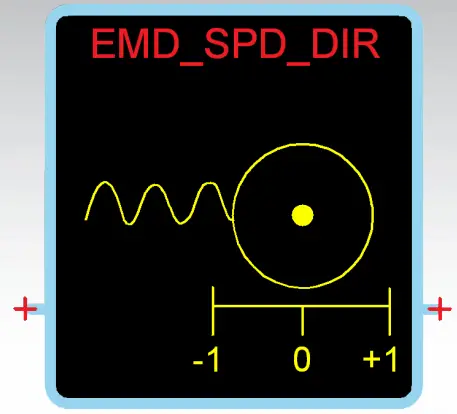
- Dir: S8 – Values: -1, 0, +1
FAQ
- What is the purpose of the EMD_SPD_DIR Function Block?
The EMD_SPD_DIR Function Block outputs rpm and directional signals based on inputs from an EMD Speed Sensor. - What are the input requirements for the EMD_SPD_DIR function block on MC Controllers?
The input requirements for MC Controllers are Spd, MFIn, and DirIn. - What is the voltage range for the Direction input (Dir In) of the EMD_SPD_DIR Function Block?
The voltage range for the Direction input is from 0 to 5,250 volts.
Revision history
Table of revisions
| Date | Changed | Rev |
| December 2014 | AA |
EMD_SPD_DIR Function Block
Overview
This function block outputs rpm and directional signals based on inputs from an EMD Speed Sensor. On both MC and SC controllers, this function block receives its:
- Spd input through an MFIn input.
- DirIn input through either a second MFIn input or a DigAn input.
Controller Input Requirements for EMD Function Blocks
The following tables list the controller input requirements for the EMD SPD DIR, EMD SPD DIR A, and EMD SPD DIR D function blocks.
Input Connections—MC Controllers
| Function Block | Function Block Input | Controller Input | Comment |
| EMD SPD DIR | Spd | MFIn | Determines speed via pulse signal from the sensor. |
| DirIn | MFIn | Utilizes pull-up/pull-down resistors and voltage to detect open circuit failure of the direction signal. | |
| EMD SPD DIR A | Spd | MFIn | Determines speed via pulse signal from the sensor. |
| DirIn | DigAn | Only detects when direction signal voltage is outside the expected ranges but lacks pull-up/pull-down resistors for open circuit detection. | |
| AnIn | Only detects when direction signal voltage is outside the expected ranges but lacks pull-up/pull-down resistors for open circuit detection. | ||
| EMD SPD DIR D | Spd | MFIn | Determines speed via pulse signal from the sensor. |
| DigDir | DigIn | Provides no fault detection for the direction signal. | |
| DigAn | Provides no fault detection for the direction signal. |
Input Connections—SC Controllers
| Function Block | Function Block Input | Controller Input | Comment |
| EMD SPD DIR | Spd | MFIn | Determines speed via pulse signal from the sensor. The controller input must be labeled Dig/Ana/Freq. |
| DirIn | MFIn | Utilizes pull-up/pull-down resistors and voltage to detect open circuit failure of the direction signal. | |
| DigAn | Utilizes pull-up/pull-down resistors and voltage to detect open circuit failure of the direction signal. |
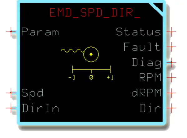
Function Block Inputs
| Item | Type | Range | Description |
| Param | Bus | —— | Input for common parameters that can be applied to multiple function blocks. See About the Param Input on page 11 for more information. |
| Spd | Bus | —— | Input for a bus with:
|
| Per | U32 | 1,250 to
10,000,000 |
The measured period output by the Speed Sensor.
The function block uses the Per signal, Count signal, and Puls/Rev parameter value to calculate its RPM output. 10,000 = 1,000 μs. |
| Count | U16 | 0 to 65,535 | The measured count per program loop output by the Speed Sensor.
The function block uses the Per signal, Count signal, and Puls/Rev parameter value to calculate its RPM output. 1,000 = 1,000. |
| Config | Sub-bus | —— | Contains the signals that configure this input. |
| Dir In | Bus | —— | Input for a bus with:
|
| Volt/Voltage | U16 | 0 to 5,250 | The measured voltage of the direction signal that the Speed Sensor outputs, which the block uses to determine direction. |
| Config | Sub-bus | —— | Contains the signals that configure this input. |
Outputs
Function Block Outputs
| Item | Type | Range | Description |
| Status | U16 | —— | Reports the function block’s status.
This function block uses a non-standard bitwise scheme to report its status and faults.
|
| Fault | U16 | —— | Reports the function block’s faults.
This function block uses a non-standard bitwise scheme to report its status and faults.
|
| Diag | Bus | —— | Outputs a bus with Freq, FltTmrDir, and FltTmrFreq signals that are available for troubleshooting. |
| Freq | U32 | 0 to 1,000,
000,000 |
The measured frequency of the Speed Sensor. 100,000 = 10,000 Hz. |
| FaultTmrFreq | U16 | 0 to 65,535 | When a frequency fault:
|
| FltTmrDir | U16 | 0 to 65,535 | When a direction fault:
|
| RPM | U16 | 0 to 2,500 | Speed sensor revolutions per minute.
The function block clamps this output at 2,500. 1 = 1 rpm. |
| dRPM | U16 | 0 to 25,000 | Speed sensor revolutions per minute x 10 (deciRPM). The function block clamps this output at 25,000. |
| Dir | S8 | -1, 0, +1 | The Speed Sensor’s direction of rotation.
|
About Function Block Connections
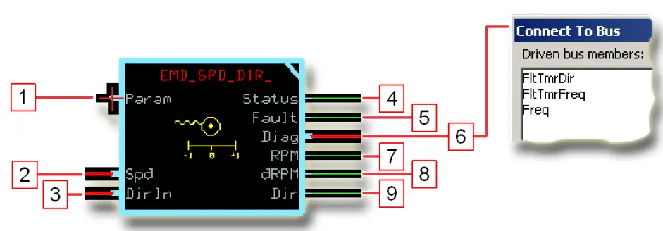
About Function Block Connections
| Item | Description |
| 1. | Input for common parameters that can be applied to multiple function blocks. |
| 2. | Input for a bus with:
|
| 3. | Input for a bus with:
|
| 4. | Reports the status of the function block. |
| 5. | Reports the faults of the function block. |
| 6. | Outputs a bus with Freq, FltTmrDir, and FltTmrFreq signals that are available for troubleshooting. |
| 7. | Speed sensor revolutions per minute. |
| 8. | Speed sensor revolutions per minute x 10 (deciRPM). |
| 9. | The Speed Sensor’s direction of rotation.
|
Status and Fault Logic
Unlike most other PLUS+1 compliant function blocks, this function block uses non-standard status and fault codes.
Status Logic
| Status | Hex* | Binary | Cause | Response | Correction |
| A parameter is out of range. | 0x0008 | 1000 | Puls/Rev, FaultDetTm, or DirLockHz parameter is out of range. | The function block clamps the out-of-range value at either its upper or lower limit. | Get the out-of-range parameter back within its range. |
* Bit 16 set to 1 identifies a standard Danfoss status or fault code.
Fault Logic
| Fault | Hex* | Binary | Cause | Response | Delay† | Latch‡ | Correction |
| Per signal in the function block’s Spd input is too low. | 0x0001 | 0001 | Per signal < 1,250 Hz. | The function block outputs its maximum RPM and dRPM values. | Y | N | Check for hardware issues, such as electrical noise, that can produce an invalid Per signal value. |
| Volt/Voltage signal in the function block’s Spd input is out of range. | 0x0002 | 0010 | Volt/Voltage signal is between 1,000 and 2,500 mV
and the block receives no pulses from the Speed Sensor. |
The function block sets its RPM and dRPM outputs to 0. | Y | N | Check for hardware issues, such as electrical noise, that can produce an invalid Volt/ Voltage signal value. |
| Volt/Voltage signal in the function block’s Dir input is out of range. | 0x0004 | 0100 | Volt/Voltage signal is between 1,000 and 2,500
mV. |
The function block sets its Dir output to 0. | Y | N | Check for hardware issues, such as electrical noise, that can produce an invalid Volt/ Voltage signal value. |
* Bit 16 set to 1 identifies a standard Danfoss status or fault code.
† A delayed fault is reported if the detected fault condition persists for a specified delay time. A delayed fault cannot be cleared until the fault condition remains undetected for the delay time.
‡ The function block maintains a latched fault report until the latch releases.
Function Block Parameters
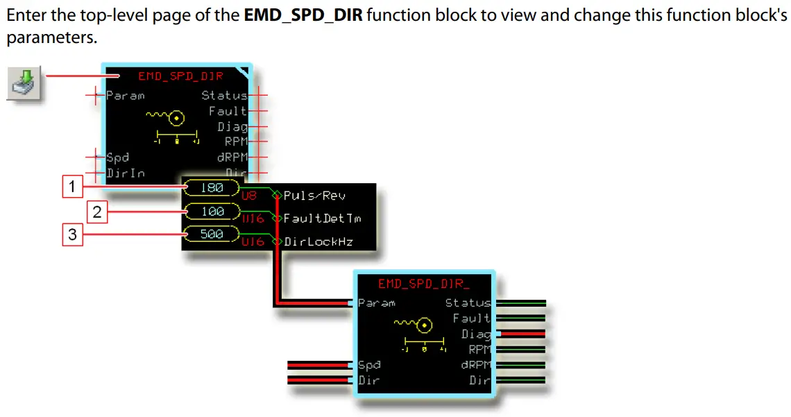
Function Block Parameters
| Item | Type | Range | Description |
| 1. Puls/Rev | U8 | 20–120, 180 | Number of pulses per revolution of the Speed Sensor. Refer to the EMD Speed Sensor Technical Information (Danfoss part L1017287) for the correct value. |
| 2. FaultDetTm | U16 | 0–65,535 | Sets the time between when the function block detects a:
|
| 3. DirLockHz | U16 | 0–8,000 | Sets the frequency above which the function block’s Dir output locks. Above this frequency, the function block does not report changes in direction.
1,000 = 1,000 Hz. |
About the Param Input
Use the Param input to input external parameter values to this function block.

Figure Details
| Item | Description |
| 1. | Inside the function block’s top-level page before you modify this page to accept common parameters through its Param input. |
| 2. | Inside the function block’s top level page after you modify this page to accept common parameters through its Param input. |
Controller Configurations
Inputs on MC and SC controllers require configuration to work with this function block. See:
- MC Controller Configurations on page 12.
- SC Controller Configurations on page 16.
MC Controller Configurations
Input Configurations
| Function Block Input | Compatible Input Type | Configuration Action |
| Spd | MFIn | Delete the:
|
| DirIn | MFIn | Delete the:
|
| DigAn | Delete the:
|
Controller Configurations
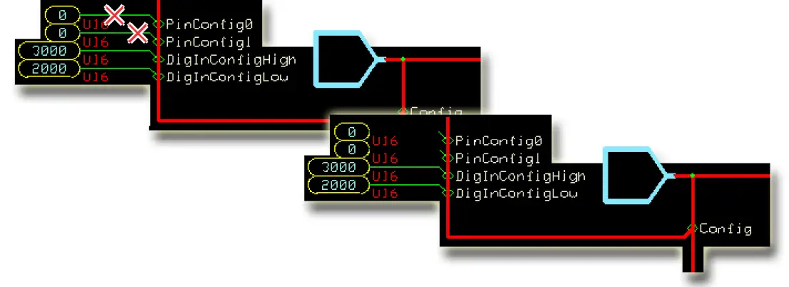
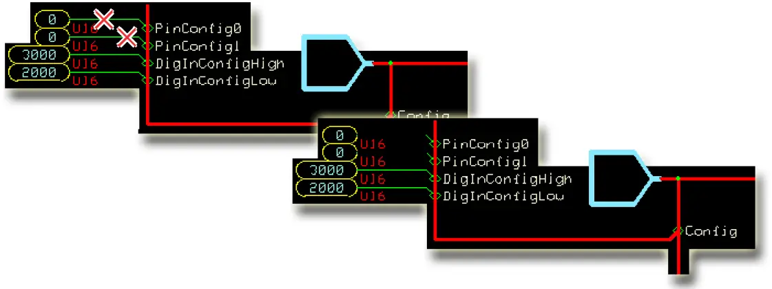
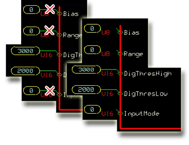
How to Configure an MFIn for the Spd Input
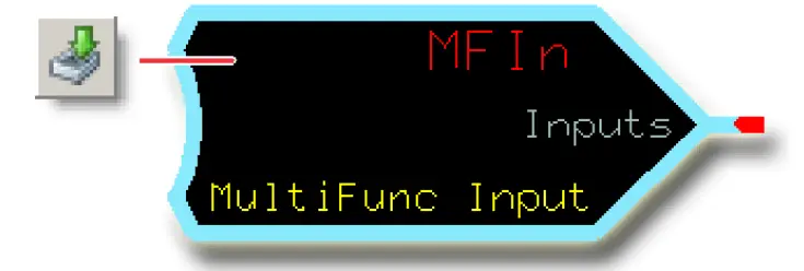
- In the GUIDE template, enter the Inputs page.
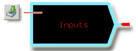
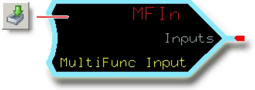
- Enter the MFIn that receives the input signal.
- Make the changes that are shown in the following figure.
Controller Configurations
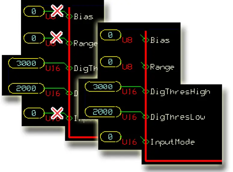
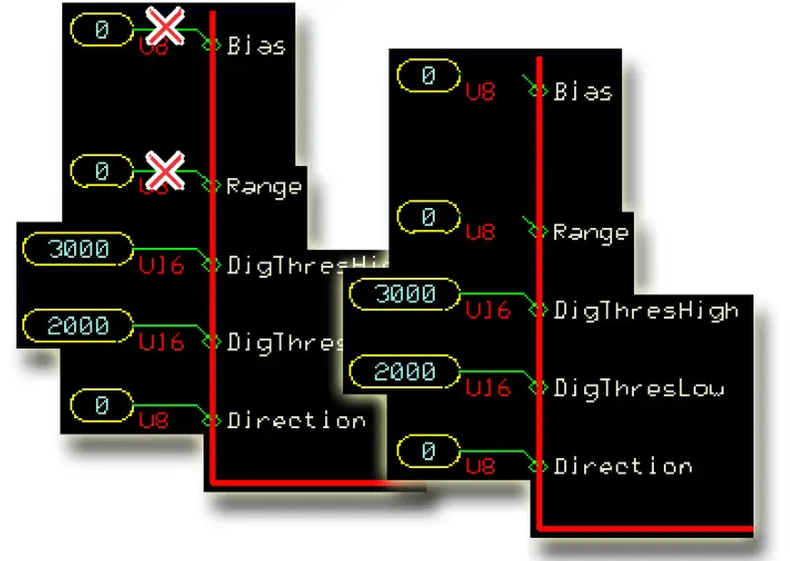
How to Configure a MFIn for the DirIn Input
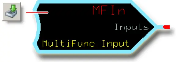
- In the GUIDE template, enter the Inputs page.

- Enter the MFIn that receives the input signal.

- Make the changes that are shown in the following figure.
How to Configure a DigAn for the DirIn Input
- In the GUIDE template, enter the Inputs page.

- Enter the DigAn page that receives the input signal.

- Make the changes that are shown in the following figure.

SC Controller Configurations
Input Configurations
| Function Block Input | Compatible Input Type | Configuration Action |
| Spd | MFIn* | Delete the:
|
| DirIn | MFIn | Delete the:
|
| DigAn | Delete the:
|
* The MFIn that you use must be labeled Dig/Ana/Freq.
† If present.
How to Configure an MFIn for the Spd Input
- In the GUIDE template, enter the Inputs page.

- Enter the MFIn that receives the input signal.
- Make the changes that are shown in the following figure.
How to Configure an MFIn for the DirIn Input
- In the GUIDE template, enter the Inputs page.

- Enter the MFIn that receives the input signal.
- Make the changes that are shown in the following figure.
How to Configure a DigAn for the DirIn Input
- In the GUIDE template, enter the Inputs page.

- Enter the DigAn that receives the input signal.

- Make the changes that are shown in the following figure.
Products we offer
- Bent Axis Motors
- Closed Circuit Axial Piston Pumps and Motors
- Displays
- Electrohydraulic Power Steering
- Electrohydraulics
- Hydraulic Power Steering
- Integrated Systems
- Joysticks and Control Handles
- Microcontrollers and Software
- Open Circuit Axial Piston Pumps
- Orbital Motors
- PLUS+1® GUIDE
- Proportional Valves
- Sensors
- Steering
- Transit Mixer Drives
Danfoss Power Solutions is a global manufacturer and supplier of high-quality hydraulic and electronic components. We specialize in providing state-of-the-art technology and solutions that excel in the harsh operating conditions of the mobile off-highway market. Building on our extensive applications expertise, we work closely with our customers to ensure exceptional performance for a broad range of off-highway vehicles.
We help OEMs around the world speed up system development, reduce costs and bring vehicles to market faster.
Danfoss – Your Strongest Partner in Mobile Hydraulics.
Go to www.powersolutions.danfoss.com for further product information.
Wherever off-highway vehicles are at work, so is Danfoss. We offer expert worldwide support for our customers, ensuring the best possible solutions for outstanding performance. And with an extensive network of Global Service Partners, we also provide comprehensive global service for all of our components.
Please contact the Danfoss Power Solution representative nearest you.
Comatrol
www.comatrol.com
Schwarzmüller-Inverter www.schwarzmueller-inverter.com
Turolla
www.turollaocg.com
Valmova
www.valmova.com
Hydro-Gear
www.hydro-gear.com
Daikin-Sauer-Danfoss www.daikin-sauer-danfoss.com
Danfoss
Power Solutions (US) Company 2800 East 13th Street
Ames, IA 50010, USA
Phone: +1 515 239 6000
Danfoss
Power Solutions GmbH & Co. OHG Krokamp 35
D-24539 Neumünster, Germany Phone: +49 4321 871 0
Danfoss
Power Solutions ApS Nordborgvej 81
DK-6430 Nordborg, Denmark Phone: +45 7488 2222
Danfoss
Power Solutions (Shanghai) Co., Ltd.
Building #22, No. 1000 Jin Hai Rd Jin Qiao, Pudong New District Shanghai, China 201206 Phone: +86 21 3418 5200
Danfoss can accept no responsibility for possible errors in catalogues, brochures and other printed material. Danfoss reserves the right to alter its products without notice. This also applies to products already on order provided that such alterations can be made without changes being necessary in specifications already agreed.
All trademarks in this material are property of the respective companies. Danfoss and the Danfoss logotype are trademarks of Danfoss A/S. All rights reserved.
L1429328 • Rev AA • December 2014
www.danfoss.com
© Danfoss A/S, 2014
Documents / Resources
 |
Danfoss Compliant EMD Speed Direction Function Block [pdf] User Manual Compliant EMD Speed Direction Function Block, Speed Direction Function Block, Direction Function Block, Function Block, Block |