![]()
User Manual
Version 1.15
2024/03/07
HRT-711
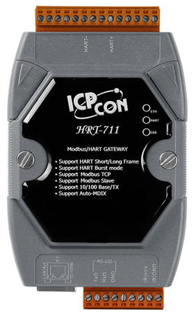
HRT-711 Modbus TCP to HART Gateway
Important Information
Warranty
All products manufactured by ICP DAS are under warranty regarding defective materials for a period of one year, beginning from the date of delivery to the original purchaser.
Warning
ICP DAS assumes no liability for any damage resulting from the use of this product.ICP DAS reserves the right to change this manual at any time without notice. The information furnished by ICP DAS is believed to be accurate and reliable. However, no responsibility is assumed by ICP DAS for its use, not for any infringements of patents or other rights of third parties resulting from its use.
Copyright
Copyright @ 2017 by ICP DAS Co., Ltd. All rights are reserved.
Trademark
Names are used for identification purpose only and may be registered trademarks of their respective companies.
Contact us
If you encounter any problems while operating this device, feel free to contact us via mail at: service@icpdas.com . We guarantee to respond within 2 working days.
Introduction
Modbus and HART are two kinds of famous protocols and used wildly in the fields of factory and process automation. The HRT-711 module is a Modbus/TCP and Modbus/UDP to HART gateway.
By using this module, users can integrate their HART devices into Modbus network easily. The below figure 1 shows an application example for the HRT-711 module.

1.1 Features
- Support HART Short/Long frame
- Support HART Burst mode
- Allow two HART Masters
- Support Modbus/TCP and Modbus/UDP format
- Support Modbus Slave / HART Master Mode
- Support Firmware Update via Com Port
- Support On-line Replacement of HART Devices
- Support Acquire Long Frame Address Automatically
- Provide LED indicators
- Built-in Watchdog
- DIN-Rail or Wall Mounting
1.2 Specification
| Item | Specification | |||
| Com Port | RS-232(3 wire) | |||
| Screwed terminal block | ||||
| Fixed baud rate 115200 bps | ||||
| HART | 1 HART Modem | |||
| Screwed terminal block | ||||
| Operates as a HART Master station and supports all HART commands | ||||
| Support Short and Long Frame | ||||
| Support Point to Point or Multi-drop | ||||
| Max. 15 HART modules | ||||
| Max. 100 user commands and 32 default commands | ||||
| Ethernet | 1 x 10/100Base-TX Ethernet Controller | |||
| RJ-45 | ||||
| Auto Negotiation | ||||
| Auto MDIX | ||||
| Power | +10 ~ +30 VDC | |||
| Power reverse protection and Over-Voltage brown-out protection | ||||
| Power Consumption:2 W | ||||
| Module | Dimensions: 72 mm x 121 mm x 35 mm (W x L x H) | |||
| Operating temperature: -25 ~ 75 ºC | ||||
| Storage temperature: -30 ~ 85 ºC | ||||
| Humidity: 5 ~ 95% RH, non-condensing | ||||
| 3 x LED indicators | ||||
| ETH LED | Network Status | |||
| HART LED | HART Status | |||
| ERR LED | Error | |||
Hardware
2.1 Block Diagram

2.2 Pin Assignment

| Pin Name | Group | Description |
| HART+ | HART | Positive of HART |
| HART- | Negative of HART | |
| +VS | Power Source | V+ of Power Supply(+10 ~ +30 VDC) |
| GND | GND of Power Supply | |
| TXD | Configuration | Transmit Data of RS-232 |
| RXD | Receive Data of RS-232 | |
| GND | GND of RS-232 | |
| E1 | Modbus/TCP Modbus/UDP |
Ethernet RJ45 connector for Modbus/TCP and Modbus/UDP |
2.3 Wiring
In this section, this user’s manual will introduce the wiring for each interface.
2.3.1 RS-232
The RS-232 port of HRT-711 uses a 3-wire communication interface. It needs a unique cable, CA-0910, to wire from screwed terminal block to D-Sub 9pin connector. Users can choose between using CA-0910 for RS-232 wiring or directly connecting to D-Sub. 2.3.1.1 and 2.3.1.2 are the wiring for the RS-232 interface.
Without CA-0910
When users choose not to use CA-0910 for RS-232 wiring, users have to have a D-Sub 9pin connector to wire. The following figure is the wiring diagram for wiring without CA-0910.

With CA-0910
It is recommended that users use CA-0910 for wiring the RS-232 port. The wiring of CA-0910 and HRT-711 is shown as below.

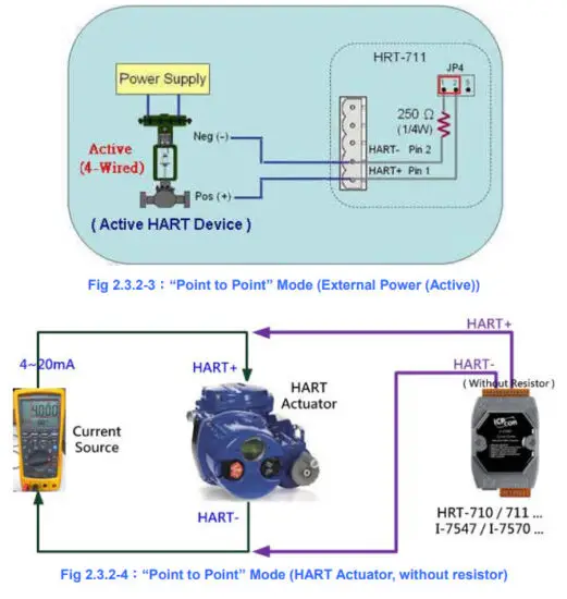
2.3.2 HART
The wiring of HART bus can be classified to the below two types.
[1] “Point to Point” Mode
[2] “Multi-Drop” Mode
(1) “Point to Point” Mode :

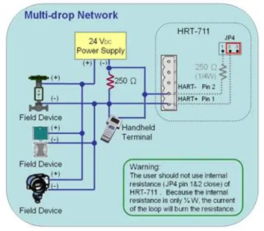
(2) “Multi-Drop” Mode :


2.3.3 Ethernet
The wiring for Ethernet is directly connecting your RJ-45 Ethernet cable to the RJ-45 port on the HRT-711.
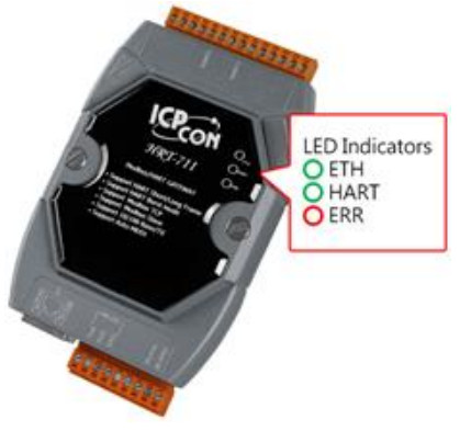
2.4 LED Indicators
The HRT-711 provides three LED indicators to indicate the module status. The descriptions are shown as follow.
| LED | Status | Description |
| ETH | Blink | Blink every 0.2 second:Receiving Ethernet packet Blink every 3 second:The network function is normal |
| Off | Ethernet Error | |
| HART | Blink | Blink every 1 second: The HRT-711 is in the initialing procedure Blink every 0.5 second: The HRT-711 is handling the burst frame sent from HART device |
| Solid | The HRT-711 is in the normal status | |
| Off | Firmware is not loaded | |
| ERR | Blink | HART communication error |
| Off | HART communication is good |
2.5 DIP Switch
The DIP switch is used for switching the mode between Init and Normal. The switch is located on the back of the module. On the init side, the module can be configured through Utility. On the normal side, the module is a gateway between HART and Modbus/TCP, Modbus/UDP protocol.
Users have to power cycle the module when switch to different mode.

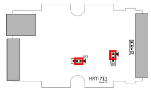
2.6 Jumpers
There are three jumpers for enabling/disabling function. The description for each jumper is shown as following table.
| Jumper | Description |
| JP2 | (1) Position 1 & 2 : Enable hardware WDT. (Default setting) (2) Position 2 & 3 : Firmware Update Mode. (JP3 should be also in the 2 & 3) |
| JP3 | (1) Position 1 & 2 : Firmware Operation Mode. (Default setting) (2) Position 2 & 3 : Firmware Update Mode. (JP2 should be also in the 2 & 3) => The detailed steps of Firmware Update, please refer to the Q04 of FAQ. |
| JP4 | The jumper can provide HART bus with 250 Ω (1/4 W) resistor. When the pin 1&2 of of JP4 is closed, the resistor will connect to HART bus. When the pin 2&3 of JP4 is closed or JP4 without jumper connected, it will disconnect the resistor from HART bus. By default, the pin1&2 of JP4 is closed. Please refer to section 2.3.2. |
2.7 Mounting

HART Introduction
3.1 Analog and Digital Signal
The HART communication protocol is based on the Bell 202 telephone communication standard and operates using the frequency shift keying (FSK, Figure 14) principle. The digital signal is made up of two frequencies – 1,200 Hz and 2,200 Hz representing bits 1 and 0, respectively. Sine waves of these two frequencies are superimposed on the direct current (dc) analog signal cables to provide simultaneous analog and digital communications.

3.2 Topology
HART bus can operate in one of the two network configurartions, point to point and multi-drop.
Point to Point
In point to point mode, the analog signal is used to communicate one process variable and the digital signal gives access to secondary variables and other data that can be used for operations, commissioning, maintenance and diagnostic purposes. Only one HART slave device can exist in HART bus and the polling address must be zero.

Multi-drop
In multi-drop mode, all process values are transmitted digitally. The polling address of all field devices must be bigger than 0 and between 1 ~ 15. The current through each device is fixed to a minimum value (typically 4 mA). The maximum HART device number in HART bus is up to 15.
NOTE:The built-in resistor in HRT-711 is 250 Ohm with 1/4W. Therefore, HRT-711 supports to connect the maximum 7 HART devices simultaneously. If the HART devices in multi-drop mode are more than 7, then users need to disconnect the built-in resistor in HRT-711 (prevent to burn down) and use an external 250 Ohm resistor with 1W.
3.3 HART Frame
The HART frame format is shown as below.

| Field | Description | |||||||||||||||||||
| Preamble | All frames transmitted by HART master or slave devices are preceded by a specified number of “0xFF” characters and they are called the preamble. The number of preamble can’t be less than 5 and more than 20 | |||||||||||||||||||
| Delimiter | This data can indicate the frame is long or short frame and the frame is master frame, slave frame or burst frame. | |||||||||||||||||||
| Address | If the HART frame is short frame, the address field is only one byte. If it is long frame, the address field are 5 bytes and include manufacturer ID, device type and device ID. | |||||||||||||||||||
| Command | The HART command set can be devided into Universal, Common Practice and Device-Speific class. These three class shown as below:
Please refer to Appendix A for more detail of HART command |
|||||||||||||||||||
| Byte Count | It is the number of bytes between it and the check byte the end of the HART frame. | |||||||||||||||||||
| Response Code | It includes two bytes of status. These bytes convey three types of information: Communication errors, Command response problems and Field device status. They are shown as below.
NOTE:When first byte shows the communication error, the value of the second byte is 0 |
|||||||||||||||||||
| Byte 0 represents the communication error or response code | ||||||||||||||||||||
| This byte is used for error status when Bit7 is 1. The status bits are shown as follow | ||||||||||||||||||||
| Bit7 | Bit6 | Bit5 | Bit4 | Bit3 | Bit2 | Bit1 | Bit0 | |||||||||||||
| Field | Description | |||||||||||||||||||||||||||||||||||||||||||||
| Parity Error | Overru n error | Framin g Error | Checksu m error | 0(Reserved) | RX buffer overflow | Overflow (Undefin e) | ||||||||||||||||||||||||||||||||||||||||
| This byte is used for response code when Bit7 is 0. | ||||||||||||||||||||||||||||||||||||||||||||||
| Bit7 | Bit6 | Bit5 | Bit4 | Bit3 | Bit2 | Bit1 | Bit0 | |||||||||||||||||||||||||||||||||||||||
| 0 | Response Code | |||||||||||||||||||||||||||||||||||||||||||||
|
||||||||||||||||||||||||||||||||||||||||||||||
| Byte 1 indicates field device status | ||||||||||||||||||||||||||||||||||||||||||||||
| Bit 7 | Field device malfunction | |||||||||||||||||||||||||||||||||||||||||||||
| Bit 6 | Configuration changed | |||||||||||||||||||||||||||||||||||||||||||||
| Bit 5 | Cold start | |||||||||||||||||||||||||||||||||||||||||||||
| Bit 4 | More status available | |||||||||||||||||||||||||||||||||||||||||||||
| Bit 3 | Analog output current fixed | |||||||||||||||||||||||||||||||||||||||||||||
| Bit 2 | Analog output saturated | |||||||||||||||||||||||||||||||||||||||||||||
| Bit 1 | Non-primary variable out of limits | |||||||||||||||||||||||||||||||||||||||||||||
| Bit 0 | Primary variable out of limits | |||||||||||||||||||||||||||||||||||||||||||||
| Data | The contents of the data are decided by HART command number. | |||||||||||||||||||||||||||||||||||||||||||||
| Check Byte | Every HART frame has a check byte at the last data byte. HART device can detect error frame by this byte. | |||||||||||||||||||||||||||||||||||||||||||||
Modbus Communication
4.1 Module Execution Process
When the HRT-711 module is started, it will perform the Initial mode first and then the Operation mode.
(1) When HRT-711 runs under Initial mode, it will execute all initial command and the HART LED will flash.
(2) When HRT-711 runs under Operation mode, it will execute all polling command automatically and the HART LED will always on.
4.2 Modbus / HART Mapping Table
Users can access the HART device by using these Modbus address defined by HRT-711 module.
These Modbus address can be divided into two parts as below.
(1) Input Data Area (FC04)
(2) Output Data Area (FC06, FC16)
[ Note ]
The meaning of every Modbus address in the below table is based on the setting of SWAP Mode to be None. If the setting of SWAP Mode is Byte or WORD or W&B, then the meaning of every Modbus address in the below table will be moved one byte or word address
4.2.1 Input Data Area-User CMD Data
| Modbus Addr (Hexadecimal) | Modbus Addr (Decimal) | Description |
| 0x0~1F3 | 0~499 | User CMD Data |
4.2.2 Input Data Area-Module State Data
| Modbus Addr (Hexadecimal) | Modbus Addr (Decimal) | Description | ||||
| 0x1F4 | 500 |
|
||||
| 0x1F5 | 501 |
|
||||
| 0x1F6 0x1F7~1F9 |
502 503~505 |
Reserved |
NOTE 1:The module state machine represents current state of command handling. The meanings of the states are shown in the following table.
| Value | Status |
| 0 | Idle |
| 1 | Waiting to send HART command |
| 2 | Sending HART command. |
| 3 | Waiting to receive HART data |
| 4 | Receiving HART data. |
NOTE 2:In HRT-711, the module request and receive command and error count are used 1 byte respectively. Each request, receive or error will increase this byte until 256, then the value will start from 0 again.
NOTE 3:The module error status records the latest error status. The status is shown as following table.
| Value | Error Status |
| 0 | No error |
| 1 | The command has never be executed |
| 2 | Receive timeout, can’t receive any HART data |
| 3 | Receive HART data is too short |
| 4 | The delimiter of HART data has some error |
| 5 | The address (the bit of master type) of HART data has some error |
| 6 | The address (the bit of burst mode) of HART data has some error |
| 7 | The command of HART data has some error |
| 8 | The parity of HART data has error |
| 9 | The communication with HART slave device has some error and the error messages are recorded in the responses codes |
NOTE 4:The module command index records the latest command index. There is no error occur when this byte is 255.
4.2.3 Input Data Area-Default CMD 0 Data
The HRT-711 will automatically add two default commands, CMD 0 and CMD 3, when add a HART device. The following table represents the default CMD 0 data Modbus address mapping.
| Modbus Addr (Hexadecimal) | Modbus Addr (Decimal) | Description |
| 0x1FA~200 | 506~512 | Default CMD 0 input data of Module 0 |
| 0x201~207 | 513~519 | Default CMD 0 input data of Module 1 |
| 0x208~20E | 520~526 | Default CMD 0 input data of Module 2 |
| 0x20F~215 | 527~533 | Default CMD 0 input data of Module 3 |
| 0x216~21C | 534~540 | Default CMD 0 input data of Module 4 |
| 0x21D~223 | 541~547 | Default CMD 0 input data of Module 5 |
| 0x224~22A | 548~554 | Default CMD 0 input data of Module 6 |
| 0x22B~231 | 555~561 | Default CMD 0 input data of Module 7 |
| 0x232~238 | 562~568 | Default CMD 0 input data of Module 8 |
| 0x239~23F | 569~575 | Default CMD 0 input data of Module 9 |
| 0x240~246 | 576~582 | Default CMD 0 input data of Module 10 |
| 0x247~24D | 583~589 | Default CMD 0 input data of Module 11 |
| 0x24E~254 | 590~596 | Default CMD 0 input data of Module 12 |
| 0x255~25B | 597~603 | Default CMD 0 input data of Module 13 |
| 0x25C~262 | 604~610 | Default CMD 0 input data of Module 14 |
| 0x263~269 | 611~617 | Default CMD 0 input data of Module 15 |
4.2.4 Input Data Area-Default CMD 3 Normal Format Data
When configure HRT-711 default CMD 3 to normal format, the data of Modbus address for each HART device is shown as following table.
| Byte 0 | Byte 1 | Byte 2 | Byte 3 | Byte 4 |
| Unit | Primary Variable of HART device (In IEEE 754 format) | |||
| Byte 5 | Byte 6 | Byte 7 | Byte 8 | Byte 9 |
| Unit | Secondary Variable of HART device (In IEEE 754 format) | |||
| Byte 10 | Byte 11 | Byte 12 | Byte 13 | Byte 14 |
| Unit | Tertiary Variable of HART device (In IEEE 754 format) | |||
| Byte 15 | Byte 16 | Byte 17 | Byte 18 | Byte 19 |
| Unit | Quaternary Variable of HART device (In IEEE 754 format) | |||
| Modbus Addr (Hexadecimal) | Modbus Addr (Decimal) | Description |
| 0x26A~276 | 618~630 | Default CMD 3 Normal Format Data of Module 0 |
| 0x277~283 | 631~643 | Default CMD 3 Normal Format Data of Module 1 |
| 0x284~290 | 644~656 | Default CMD 3 Normal Format Data of Module 2 |
| 0x291~29D | 657~669 | Default CMD 3 Normal Format Data of Module 3 |
| 0x29E~2AA | 670~682 | Default CMD 3 Normal Format Data of Module 4 |
| 0x2AB~2B7 | 683~695 | Default CMD 3 Normal Format Data of Module 5 |
| 0x2B8~2C4 | 696~708 | Default CMD 3 Normal Format Data of Module 6 |
| 0x2C5~2D1 | 709~721 | Default CMD 3 Normal Format Data of Module 7 |
| 0x2D2~2DE | 722~734 | Default CMD 3 Normal Format Data of Module 8 |
| 0x2DF~2EB | 735~747 | Default CMD 3 Normal Format Data of Module 9 |
| 0x2EC~2F8 | 748~760 | Default CMD 3 Normal Format Data of Module 10 |
| 0x2F9~305 | 761~773 | Default CMD 3 Normal Format Data of Module 11 |
| 0x306~312 | 774~786 | Default CMD 3 Normal Format Data of Module 12 |
| 0x313~31F | 787~799 | Default CMD 3 Normal Format Data of Module 13 |
| 0x320~32C | 800~812 | Default CMD 3 Normal Format Data of Module 14 |
| 0x32D~339 | 813~825 | Default CMD 3 Normal Format Data of Module 15 |
4.2.5 Input Data Area-Module Error Record Data
The HRT-711 records the latest 3 error when HART communication has error. These 3 records are put in the module error record. The format of each record is shown as following table.
| Byte 0 | The length of send data |
| Byte 1~53 | The record of send data |
| Byte 54 | The length of receive data |
| Byte 55~109 | The record of receive data |
| Byte 110~113 | The time stamp record |
| Byte 114~115 | Reserved |
| Modbus Addr (Hexadecimal) | Modbus Addr (Decimal) | Description |
| 0x33A~373 | 826~883 | Module Error Record 1 |
| 0x374~3AD | 884~941 | Module Error Record 2 |
| 0x3AE~3E7 | 942~999 | Module Error Record 3 |
4.2.6 Input Data Area-Default CMD 0&3 Status Data
It consists of two bytes. The first byte is the state of Default CMD 0 and the second byte is the state of Default CMD 3.
Ex: If the value is 0x0100 for the MB address 1000, then the low byte of the 1000 is 0x00 and the high byte of the 1000 is 0x01. It means the error status of Default CMD 0 is 0x00 and the error status of Default CMD 3 is 0x01 in Module 0.
| High Byte | Low Byte |
| CMD 3 Status | CMD 0 Status |
| Modbus Addr (Hexadecimal) | Modbus Addr (Decimal) | Description |
| 0x3E8 | 1000 | Default CMD 0&3 status of Module 0 |
| 0x3E9 | 1001 | Default CMD 0&3 status of Module 1 |
| 0x3EA | 1002 | Default CMD 0&3 status of Module 2 |
| 0x3EB | 1003 | Default CMD 0&3 status of Module 3 |
| 0x3EC | 1004 | Default CMD 0&3 status of Module 4 |
| 0x3ED | 1005 | Default CMD 0&3 status of Module 5 |
| 0x3EE | 1006 | Default CMD 0&3 status of Module 6 |
| 0x3EF | 1007 | Default CMD 0&3 status of Module 7 |
| 0x3F0 | 1008 | Default CMD 0&3 status of Module 8 |
| 0x3F1 | 1009 | Default CMD 0&3 status of Module 9 |
| 0x3F2 | 1010 | Default CMD 0&3 status of Module 10 |
| 0x3F3 | 1011 | Default CMD 0&3 status of Module 11 |
| 0x3F4 | 1012 | Default CMD 0&3 status of Module 12 |
| 0x3F5 | 1013 | Default CMD 0&3 status of Module 13 |
| 0x3F6 | 1014 | Default CMD 0&3 status of Module 14 |
| 0x3F7 | 1015 | Default CMD 0&3 status of Module 15 |
| 0x3F8~419 | 1016~1049 | Reserved |
4.2.7 Input Data Area-User CMD Error Status
The HRT-711 supports maximum 100 User CMDs. The index of the User CMD is from 0 to 99. Each Modbus address represents two User CMD statuses.
Ex: If the value is 0x0200 for the MB address 1050, then the low byte of the 1050 is 0x00 and the high byte of the 1050 is 0x02. It means the error status of User CMD Index 0 is 0x00 and the error status of User CMD Index 1 is 0x02.
| Modbus Addr (Hexadecimal) | Modbus Addr (Decimal) | Description |
| 0x41A~44B | 1050~1099 | User CMD Index 0~99 error status |
4.2.8 Input Data Area-Module Hardware Data
| Modbus Addr (Hexadecimal) | Modbus Addr (Decimal) | Description |
| 0x44C~44D | 1100~1101 | Module ID (An ASCII value to represent HART) |
| 0x44E~455 | 1102~1109 | Module Name (An ASCII value to represent the 16-byte module name) |
| 0x456~459 | 1110~1113 | Module Firmware Version (An ASCII value to represent the 8-byte firmware version) |
| 0x45A~47D | 1114~1149 | Reserved |
4.2.9 Input Data Area-Through Mode Data
| Modbus Addr (Hexadecimal) | Modbus Addr (Decimal) | Description | ||||
| 0x47E | 1150 |
|
||||
| 0x47F | 1151 |
|
||||
| 0x480 | 1152 | Receive length in through mode | ||||
| 0x481~50E | 1153~1294 | Receive data in through mode | ||||
| 0x50F~513 | 1295~1299 | Reserved |
4.2.10 Input Data Area-Default CMD 3 Simple Format Data
When configure HRT-711 default CMD 3 to simple format, the data of Modbus address for each HART device is shown as following table.
| Byte 0 | Byte 1 | Byte 2 | Byte 3 |
| Primary Variable of HART device (In IEEE 754 format) | |||
| Byte 4 | Byte 5 | Byte 6 | Byte 7 |
| Secondary Variable of HART device (In IEEE 754 format) | |||
| Byte 8 | Byte 9 | Byte 10 | Byte 11 |
| Tertiary Variable of HART device (In IEEE 754 format) | |||
| Byte 12 | Byte 13 | Byte 14 | Byte 15 |
| Quaternary Variable of HART device (In IEEE 754 format) | |||
| Modbus Addr (Hexadecimal) | Modbus Addr (Decimal) | Description |
| 0x514~51D | 1300~1309 | Default CMD 3 Simple Format data of Module 0 |
| 0x51E~527 | 1310~1319 | Default CMD 3 Simple Format data of Module 1 |
| 0x528~531 | 1320~1329 | Default CMD 3 Simple Format data of Module 2 |
| 0x532~53B | 1330~1339 | Default CMD 3 Simple Format data of Module 3 |
| 0x53C~545 | 1340~1349 | Default CMD 3 Simple Format data of Module 4 |
| 0x546~54F | 1350~1359 | Default CMD 3 Simple Format data of Module 5 |
| 0x550~559 | 1360~1369 | Default CMD 3 Simple Format data of Module 6 |
| 0x55A~563 | 1370~1379 | Default CMD 3 Simple Format data of Module 7 |
| 0x564~56D | 1380~1389 | Default CMD 3 Simple Format data of Module 8 |
| 0x56E~577 | 1390~1399 | Default CMD 3 Simple Format data of Module 9 |
| 0x578~581 | 1400~1409 | Default CMD 3 Simple Format data of Module 10 |
| 0x582~58B | 1410~1419 | Default CMD 3 Simple Format data of Module 11 |
| 0x58C~595 | 1420~1429 | Default CMD 3 Simple Format data of Module 12 |
| 0x596~59F | 1430~1439 | Default CMD 3 Simple Format data of Module 13 |
| 0x5A0~5A9 | 1440~1449 | Default CMD 3 Simple Format data of Module 14 |
| 0x5AA~5B3 | 1450~1459 | Default CMD 3 Simple Format data of Module 15 |
4.2.11 Output Data Area
| Modbus Addr (Hexadecimal) | Modbus Addr (Decimal) | Description | ||||
| 0x0~1F3 | 0~499 | User command | ||||
| 0x1F4 | 500 |
|
||||
| 0x1F5 | 501 |
|
| 0x1F6 | 502 |
|
||||
| 0x1F7~1F9 | 503~505 | Reserved | ||||
| 0x1FA~76B | 506~1899 | Reserved (For Module Configuration) | ||||
| 0x76C | 1900 |
|
||||
| 0x76D | 1901 | Send data length in through mode | ||||
| 0x76E~7FB | 1902~2043 | Send data in through mode |
NOTE 1:When write the value greater than zero, the module will clear module request count, module response count, module error count, module error status and set module error command index to 255. To complete reset procedure, user has to write 0 to this field.
NOTE 2:When set the value to be 1, the module will execute all HART polling commands automatically.
NOTE 3:If change the value, the module will refer to the index value (0~99, 255 is for through mode) of trigger command to execute the corresponding user command. Ex: If the index of trigger command is 0 and the output trigger function value is 1, when change the value of output trigger function from 1 to 2, the module will execute the user command (index = 0).
4.3 Through Mode
In this mode, users can send and receive the HART command directly. Please refer to the below steps.
Step 1:Set the Channel to 0. (Through Mode just support channel 0) [Address:1900, Low Byte]
Step 2:Set the Send length [Address:1901]
Step 3:Set the HART command data. [Address:1902~2043]
Ex: 0xFF 0xFF 0xFF 0xFF 0xFF 0x02 0x80 0x00 0x00 0x82
Step 4:Set the Auto Polling to 0. (In this mode, Auto Polling function can not be enabled.) [Address:501, Low Byte]
Step 5:Set the The index of trigger command to 255. [Address:502, High Byte]
Step 6:Get the receive count from Receive count in through mode [Address:1150, High Byte] and error count from Error count in through mode [Address:1151, Low Byte].
Step 7:Change the Output Trigger function value. [Address:502, Low Byte]
Step 8:Get the value of Receive count in through mode and Error count in through mode until one of them is different than the last value.
Step 9:If the Receive count in through mode is different than the last value, the user can get the receive length from Receive length in through mode and the user can get receive data from Receive data in through mode [Address:1153 ~ ] according to receive data length. [Address:1152]
(If the Error count in through mode is different than the last value, it means it can not receive any data.)
Utility
5.1 .NET Framework Installation
The Utility for HRT-711 needs .NET Framework to run. The version of .NET Framework to execute Utility has to greater than 2.0. If users do have this, please ignore this section and jump to section 5.2.
Microsoft .Net Framework Version 2.0:http://www.microsoft.com/downloads/details.aspx?FamilyID=0856eacb-4362-4b0d-8edd-aab15c5e04f5&DisplayLang=en
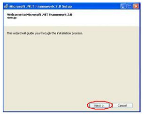
The .NET Framework install steps are shown in the below:
Step 1:Press the Next button.
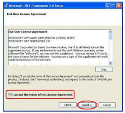
Step 2:Check the “I accept the terms of the License Agreement” and click Install button.
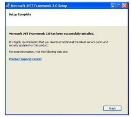
Step 3:After finishing the installation, press Finish button to exit.
5.2 Install HRT-711 Utility
Step 1:Download the installation file of HRT-711 Utility from the CD-ROM disk (CD:\hart\gateway\hrt-711\utilities\) or the web site
(ftp://ftp.icpdas.com.tw/pub/cd/fieldbus_cd/hart/gateway/hrt-711/utilities/)
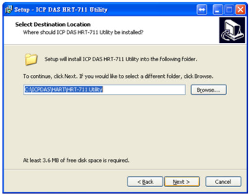
Step 2:Execute the HRT-711 Utility x.x.x.x.exe (x.x.x.x is the version of the install package) file to install the Utility, and then click Next button.

Step 3:Click the Next button to continue. If you want to change the installation destination, click Browse button to select the installation path.
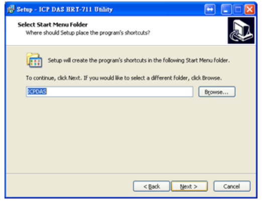
Step 4:Choose the name and the path to install in the Start Menu, and then click Next.
Step 5:Click Install to start installation
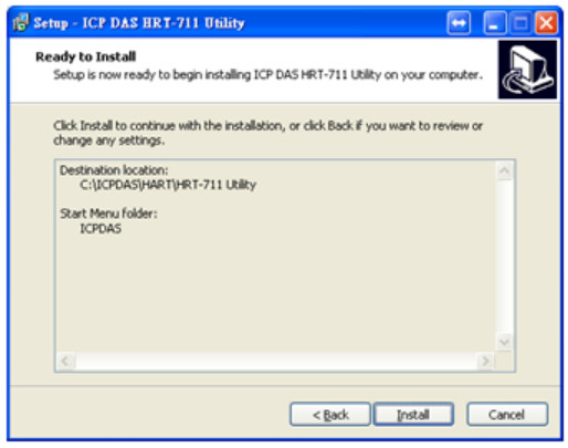
Step 6:Wait the installation finish, then check “View Patch Note.txt” if you want and click Finish to complete the installation.

Step 7:Users can execute the Utility in the following path.
 5.3 Introduction of Utility
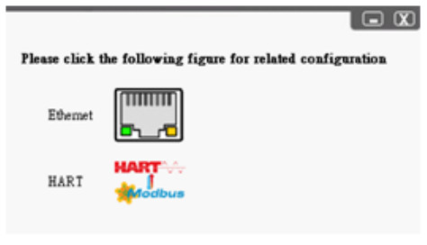
The HRT-711 has, Ethenet and HART, two interfaces. The Utility can configure these two interfaces. Users have to choose which interface to configure in the first form of the Utility. User can click the figure to choose interface. The detail of the configuration of these two interfaces will be discuss in the following section.
5.4 Configuration of Ethernet
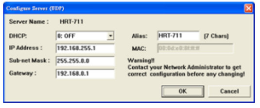
The Ethernet interface of HRT-711 handles the Modbus/TCP and Modbus/UDP protocol. Users have to configure the interface for appropriate configuration (IP, Sub-net mask…etc) for using.
Click Search Servers in this form to search all ICPDAS devices.

The HRT-711 will list in this form after searching. If the HRT-711 does not list in this form, please check the network connection or the power of the HRT-711.

Users can configure the network parameters by double clicking HRT-711 in the list. Users can modify the parameters to appropriate setting for users’ application, then click OK button to apply the new setting.
After assigning parameter, user can click Exit to exit the Network Configuration form.
5.5 Configuration of Modbus to HART
The HRT-711 is the Modbus/TCP and Modbus/UDP to HART gateway. It not only has to configure the Ethernet but also the HART interface.
NOTE:Before configuring HART interface, users have to switch the Init Mode switch to Init then power cycle the HRT-711.

The HART configuration form can devide into 5 parts. These 5 parts are Traffic Light, Current Config Module Name, Connection Status, Connection Controll and Tools. The following section will describe each part and functionalities.
5.5.1 Traffic Light
| Sign | Status |
| |
The Com port of PC has not opened yet |
| |
The Com port of PC has opened and tried to connect to the module |
| |
The PC connects to module successfully |
5.5.2 Current Config Module Name
The Current Config Module Name displaies the current module name to configure. This Utility also supports HRT-711. So, the Current Config Module Name helps users to know what module is under configuring.
5.5.3 Connection Status
| Figure | Status |
 |
The Com port of PC has not opened |
 |
The Com port of PC has opened and tried to connect to the module |
 |
The PC connects to the module successfully |
5.5.4 Connection Control
| Button | Function |
 |
When clicks this button, the PC will open the Com port and try to connect to the module. |
 |
When clicks this button, the PC will break the connection of the module and close the Com port. |
5.5.5 Tools
The Utility contains many tools for configuration and debug. The following table lists all tools and its functionalities.
| Tool | Functionality |
 |
Communication Setting The Com Port setting for the PC |
 |
Device Information Display the configuration of the device |
 |
Device Configuration Change the configuration |
 |
Default Output Data The configuration for boot-up default output of User CMD |
 |
Address Map Display the Modbus Address mapping of User CMD |
 |
Device Diagnostic Display current status of HART command of the module |
 |
Through Mode Send/Receive the HART command |
 |
Format Translation Translate Packed ASCII and IEEE 754 format |
5.5.5.1 Communication Settings
User can choose what device to configure. In this manual, please select HRT-711 in the dropdown list, and then select the Com Port number connected to HRT-711.

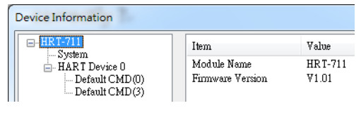
5.5.5.2 Device Information

It shows the configuration of the module. When clicking the left item, it will show the item data in the right side. About the data of these items is shown as following table.
| Node | Mouse | Behavior |
| HRT-711 | Left Click | Display configuration |
| System | Left Click | Display configuration |
| Right Click(1) | Generate Pop-up menu Basic Operation and Advanced Operation |
| HART Device N | Left Click | Display configuration |
| Default CMD (N) | Left Click | Display configuration |
| Right Click(2) | Generate Pop-up menu Basic Operation and Advanced Operation | |
| User CMD (N) | Left Click | Display configuration |
| Right Click(2) | Generate Pop-up menu Basic Operation and Advanced Operation |
(1) When right clicking the item of System, it will generate a pop-up menu. The functionalities of the menu will describe below:
Basic Operation
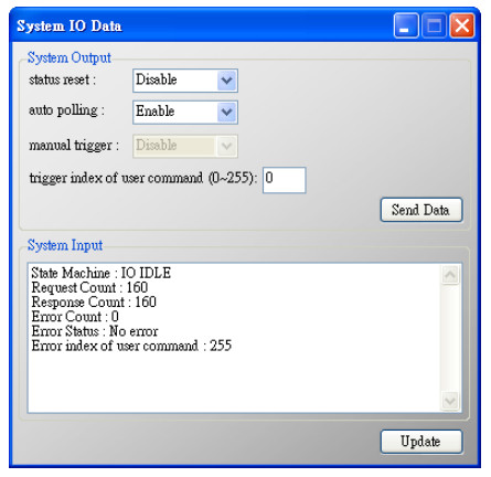
| System Output | |
| status reset | When set the item to Enable, the module will clear module request count, module response count, module error count, module error status and set module error command index to 255 |
| auto polling | When set the item to Enable, the module will execute all HART polling commands automatically |
| manual trigger | When set the item to Enable, the module will execute the user command once according to the value of trigger index of user command field |
| trigger index of user command | If users want to execute user command by manual mode, users must set the index value first |
| Send Data button | When click the button, it will update data in the System Output area to module |
| System Input | |
| System Output | |
| State Machine | It will show the state machine of module |
| Request Count | It will show the request count of HART UserCmd |
| Response Count | It will show the response count of HART UserCmd |
| Error Count | It will show the response error count of HART UserCmd |
| Error Status | It will show the error status of HART UserCmd |
| Error index of user command | It will show the latest HART UserCmd that has error happened. If the index value is 255, it means no error happened |
| Update button | When click the button, it will update System Input data from the module |
Advanced Operation
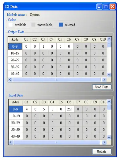
Output Data
It has 6 bytes data. When click the Send Data button, it will send the output data to module. (Modbus Address: 500~502 in Output Data Area)
Input Data
It has 6 bytes data. When click the Update button, it will update the data from module.
(Modbus Address: 500~502 in Input Data Area)
(2) When right clicking the item of Default or User CMD, it will generate a pop-up menu. The functionalities of the menu will describe below:
Basic Operation
In this function, only supports HART command 0, 1, 2, 3, 6, 11, 12, 13, 14, 15, 16, 17, 18, 19 and the different HART command will show the different user command window (EX: The window of HART command 0 and 6 is shown as below).

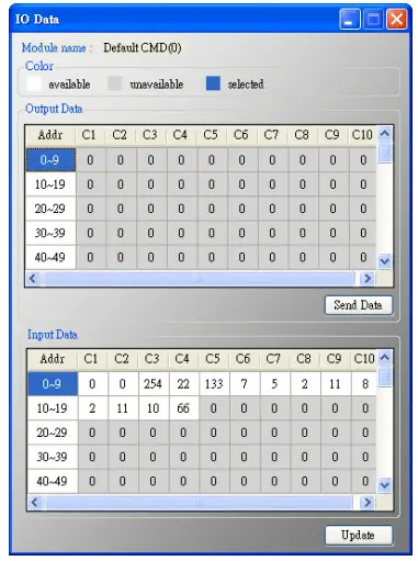
Advanced Operation
Users can wirte/read HART command/response via this form. In this form, there are two buttons Send Data and Update. When click the Send Data button, it will send the output data to the module. And when click this button, it will update the input and output data from the module.
NOTE:About the Input data area of user command, the first 2 bytes are response code1 and code2 of HART command and the left bytes are the HART command data.
5.5.5.3 Device Configuration

It will show the system configuration of HRT-711 and users can also configure HRT-711 here. When clicking the left items, it will show the corresponding item information in the right side of window. The following is detailed description.
| Node | Mouse | Behavior |
| HRT-711 | Left Click | Display configuration |
| System | Left Click | Display configuration |
| Right Click(1) | Generate Pop-up menu Edit and Add Module | |
| HART Device N | Left Click | Display configuration |
| Default CMD (N) | Left Click | Display configuration |
| Right Click(2) | Generate Pop-up menu Edit Delete and Add Command | |
| User CMD (N) | Left Click | Display configuration |
| Right Click(3) | Generate Pop-up menu Edit and Delete |
(1) When right clicking the item of System, it will generate a pop-up menu. The functionalities of the menu will describe below:
Edit

It is used to set the communicating parameters of HART and Modbus and described as below.
| System | |||||
| Cmd Interval | The polling interval of HART Cmd | ||||
| Timeout Value | The timeout value of HART Cmd. | ||||
| Auto Polling | If the function is enabled, the HRT-711 will execute all HART polling Cmd automatically. | ||||
| Retry Count | When HART comm. error happened, the HRT-711 will re-send the HART Cmd for Retry count times. | ||||
| Modbus Setting | |||||
| Swap Mode | It is used for the format of the word data in Modbus. The option are None / Byte / Word / W&B. Ex:2 words data (0x1234, 0x5678) from HRT-711. Users can set the swap mode for different data format. |
||||
| Swap Mode | Data | ||||
| None | 0x1234 | 0x5678 | |||
| Byte | 0x3412 | 0x7856 | |||
| Word | 0x5678 | 0x1234 | |||
| W&B | 0x7856 | 0x3412 | |||
Add Module

It is used to set the communicating mode for HART devices and described as below.
| Module | |
| Channel | 0~7. (Only channel 0 supports now) |
| Auto Configure | If enables this function, the HRT-711 will detect the frame type, address, preambles, manufacturer ID, device type and device ID of HART device automatically Warning:If enables this function, just supports HART Point to Point mode |
| Frame type | Short or Long frame |
| Master type | Primary or Secondary Master Warning:In general, the HRT-711 should set to the Primary Master |
| Network mode | Point to Point or Multi-drop mode. Point to Point:Only one HART slave device in HART bus Multi-drop:More than one HART devices can be in HART bus |
| Address | 0~15。 Warning:If the address of HART device is 0, it means in Point to Point mode |
| Preambles | 5~20 |
| Cmd 0 Mdoe | Disable(1) / Initial(2) / Polling(3) |
| Cmd 3 Mdoe | Disable(1) / Initial(2) / Polling(3) |
| Unique Identifier | |
| Auto Get Unique ID | If the frame type of HART slave device is long frame, users can enable this function to get unique ID automatically by short frame address |
| Manufacturer ID | Users can set the manufacturer ID for HART device. If the frame type is short, users can omit this setting |
| Device Type | Users can set the device type for HART device. If the frame type is short, users can omit this setting |
| Device ID | Users can set the device ID for HART device. If the fram type is short,users can omit this setting |
- Disable:The HRT-711 will not execute the default HART Cmd
- Initial:The HRT-711 will execute the default HART Cmd automatically when in Initial mode.
- Polling:The HRT-711 will execute the default HART Cmd automatically when in Operation mode.
(2) When right clicking the item of HART Device N, it will generate a pop-up menu.
The functionalities of the menu will describe below:
Edit
Same as the selection Add Command in the pop-up menu when right click System, please refer to that section.
Delete
Delete current selected module
Add Command

It is used to set the communicating parameter for HART User CMD. The details are described as below:
| Command | |
| Command Num | Set the HART command number |
| Mode | Initial(1) / Polling(2) / Manual(3) |
| Format | Normal(4) / Simple(5) (Data exchange format between HART and Modbus) |
| In Size | Set the input data length of HART command. Note: The size includes 2 bytes response code and data size of HART command. (Ex: HART Cmd 0 = 2(response code) +12 =14) |
| Out Size | Set the output data length of HART command. |
| In Offset | Set the input offset of HART returned command data. (HG_Tool v1.5.0 or newer supported, refer to example FAQ26) |
- Initial:The module will run this command in initial mode
- Polling:The module will run this command in operation mode
- Manual:The module will run this command by manual
- Normal:When read / write HART data by Modbus, the data format is HART standard command format
- Simple:When read / write HART data by Modbus, the data format is simple format defined by HRT-711. The detailed description, please refer to the Appendix B. (In this mode, the HMI or SCADA software can read or write HART data and don’t need to process any data. Now, it is only supported HART command number: 1, 2 and 3.)
(3) When right clicking the item of User CMD (N), it will generate a pop-up menu. The functionalities of the menu will describe below:
Edit
Same as the selection Add Command in the pop-up menu when right click HART Device N, please refer to that section.
Delete
Delete current selected User CMD (N)
5.5.5.4 Default Output Data
It is used to set the default value for all UserCMD output data.
(1) Click the left User CMD item and if the output length of the User CMD is not zero, then the occupied address will be blue in the right window.
(2) Double click the address field and it will show the Data Edit window to set the default value.
When finished all configuration, click Save to Device button to apply all settings. (The module will reboot when click Save to Device button)

5.5.5.5 Address Map
It is used to show the MB address for all User CMD.
(1) Click the left User CMD item and the occupied address of the User CMD will be blue in the right Modbus AO or Modbus AI table.
(2) The data of Modbus AI table can be read by Modbus Function Code 4.
(3) The data of Modbus AO table can be read by Modbus Function Code 3 and written by Modbus Function Code 6 or 16.
NOTE:The Modbus address of the default command is fixed, so users can refer to section 4.2 to get the address.

5.5.5.6 Device Diagnostic
It is used to show the status of HART command in the HRT-711.
(1) Click the left User CMD item and the icon of the item will show the status described as below:
| Figure | Status |
| It means no error | |
 |
It means the command has never been executed |
| It means the command has error and the error status shows at the right side of the window | |
 |
It means the item is selected |
(2) Status Update button:Refresh the status of HART Cmd
(3) Record button:The HRT-711 records the latest error command and saves to Record 1~3. Users can get these records by click Record 1, Record 2 and Record 3 button.

5.5.5.7 Through Mode
It is used to send / receive HART command directly. Users have to check the items below before using through mode function.
(1) The RUN LED is always on.
(2) The auto polling function is disabled.
Here is an example to send / receive HART command 0:
Step 1 In Send field, fill in the data“0xFF 0xFF 0xFF 0xFF 0xFF 0x02 0x80 0x00 0x00” and then click Send button to send HART Cmd.
Step 2 Click Update button to show the response of HART device.

5.5.5.8 Format Translation
Here we provide some tools for HART communication. Packed ASCII Translate tool can convert Packed ASCII into ASCII format. IEEE754 Translate tool can convert IEEE754 into byte format.
| Features | Description |
| Packed ASCII Translate | It can be used to convert between Packed ASCII and ASCII format |
| IEEE 754 Translate | It can be used to convert between IEEE754 and DWORD format |
FAQ
Q01 : How to add HART devices to HRT-711 ?
1. Add first HART device: (Ex: Add ABB AS800 HART device)
[ Step 1 ] Connect to HRT-711 and use “HRT-711 Utility” to start configuration (1) Select HART in the first page of the Utility and switch operation mode to “Init”.
 [1] If HRT-711 is the “RevB” version (as the below figure), users need to set the parameters of HRT-711 in the “Normal” mode.

(2) Selecting device to HRT-711 and switching to appropriate com port in the Communication Setting, and then click OK
(3) Click the “Connect” button to connect HRT-711 module

[ Step 2 ] Deleting the default HART device setting in HRT-711
Once successfully connected to HRT-711, the traffic light indicator will change to green (![]() ) to indicate that the Utility can start configuring HRT-711. Now, users will need to delete the default configuration by clicking Device Configuration option on the right side of the Utility.
) to indicate that the Utility can start configuring HRT-711. Now, users will need to delete the default configuration by clicking Device Configuration option on the right side of the Utility.
Follow the figure below to delete the default configuration for preparing add a new HART device.

Users can now adding new HART device by right clicking System item.

(1) Click the “Save to Device” button to save the new HART device setting to HRT-711

2. Add more than one HART devices : (Ex : Add ABB AS800 (Addr=2) and Foxboro I/A Pressure (Addr=1) HART devices)
[ Step 1 ] Follow the previous step to delete default configuration
[ Step 2 ] Add two new HART device setting
The following figures are the settings for these two HART devices.

(1) Click the “Save to Device” button to save the new HART device setting to HRT-711

Q02 : How to make sure that HRT-711 gets the HART device data correctly ?
After adding HART device setting to HRT-711 module (refer to Q01), then users can follow the below steps.
(1) Make sure HRT-711 runs in the “Normal” mode and HG_Tool is well connected to HRT-711.
Then click “Device Information” button.

[ Check I/O Data of the Default CMD(0) ]
(2) Right click the button on the “Default CMD(0)” item and choose the “Basic operation” option to open the “I/O Data” screen of the “Default CMD(0)”

(3) The following figure shows I/O Data of the “Default CMD(0)” is OK and NG


[ Check I/O Data of the Default CMD(3) ]
(4) Right click the button on the “Default CMD(3)” item and choose the “Basic operation” option to open the “I/O Data” screen of the “Default CMD(3)”

(5) The following figure shows I/O Data of the “Default CMD(3)” is OK and NG


(6) After testing the I/O data of the “Default CMD(0)” and “Default CMD(3)” , when the result is ok, it means that the communication between HRT-711 and HART devices is ok.
Q03 : How to map HART device CMD(3) data directly to SCADA or HMI ?
(1) Make sure that the connection between HRT-711 and HART device is good. (Refer to Q02)
(2) Set “Swap Mode” of system setting in HRT-711 to be “W&B”.
[1] In “Device Configuration” screen, right click the button of mouse on “System” item and click the “Edit” option to open “System Edit” screen like Figure 3-1


(3) Read HART data by Modbus TCP from HRT-711.
[1] The HRT-711 provides the MB Address 1300 ~ 1459 (Default CMD(3)(S) Data for Module 0 ~ 15 in HRT-711 => The detailed information refers to the sector 4.3 of users’ manual) and users can map the CMD(3) data of HART device to SCADA directly with these Modbus address 1300 ~ 1459.
[2] For the “Default CMD(3)(S) data of Module 0” in HRT-711, the mapped MB address is 1300 ~ 1309. The below MB/RTU client will use the “Modscan” and “Modbus Poll” tool to show the CMD(3) data of HART device by polling Modbus address 1300 ~ 1309.
<1> Confirm the connection between Utility and HRT-711 is disconnected.
<2> Make sure the HRT-711 is in the Normal operation. ( Set the “Dip Switch” on the back of HRT-711 to be “Normal” and reboot HRT-711. )
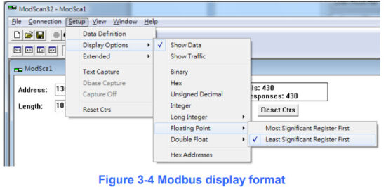
<3> Set the “Display” mode to be “Float” format as Figure 3-4
<4> Fill the “IP Address” & “Port Number” and click “OK” button to connect to HRT-711, e.g.
Figure 3-5

<5> The CMD(3) data of HART device is successfully read, e.g. Figure 3-6

[ Note ] ModScan designed to use PLC address (Base 1), so the polling address entered needs to be 1301. Users can make sure the actual polling address is [05][14] (1300) by selecting “Show Traffic” of the “Display Option” within “Setup” menu after successful connected, shown as Figure 3-7

<6> Check and modify Modbus Poll Address Base types and display formats like Figure 3-8.

<7> Set the “Read/Write Definition” of Modbus Poll like Figure 3-9.

[ Note ] The polling address is 1300 in this case because “Protocal Address (Base 0)” has been selected for Modbus Poll. If “PLC Address Poll (Base 1)” has been selected instead, then the address needs to be set as 1301. Users can make sure the actual polling address is [05][14] (1300) by checking the “Communication” dialog from “Display” menu after successful connected, shown as Figure 3-10

<8> Set the “Com Port” parameters and click “OK” button to connect to HRT-711 like Figure 3-11.

<9> The CMD(3) data of HART device is shown like Figure 3-12.

| Byte Index | Format | Description |
| 00~03 | Float | Primary Variable Current |
| 04~07 | Float | Primary Variable |
| 08~11 | Float | Secondary Variable |
| 12~15 | Float | Tertiary Variable |
| 16~19 | Float | Quaternary Variable |
Q04 : How to update the firmware of HRT-711 ?
A04: (2018/05/22)
[ For HRT-710 hardware v1.31 and firmware v1.0 or newer ]
The firmware update function is supported for users. Please follow the below steps.
※ HW_v1.xx just supports firmware v1.xx.
[ For HRT-710 hardware v2.1 and firmware v2.0 or newer ]
The firmware update function is supported for users. Please follow the below steps.
※ HW_v2.xx (casing with „RevB‟ characters) just supports firmware v2.xx.

![]() If you accidentally update the firmware to the wrong hardware (Ex. update version 2.0 to hardware version v1.31), it will cause a boot abnormality.
If you accidentally update the firmware to the wrong hardware (Ex. update version 2.0 to hardware version v1.31), it will cause a boot abnormality.
Please refer to the following procedure to renew the firmware.
[ HART Firmware Update ]
(1) Download the newest firmware of HRT-711.
(Download from: https://www.icpdas.com/en/download/show.php?num=1688&model=HRT-711 )
(2) Turn off the power. Set HRT-711 to be “Init” mode and open the upper chassis of HRT-711.
Then switch jumper to pin 2 & 3 for JP2 and JP3.

(3) Using RS-232 cable to connect PC and HRT-711, and then turn on the power.
(At this time, all LED states are divided into two types, please refer to the following table)
| Hardware Version | v1.xx | v2.xx |
| All LED | All Off | Blinks every 500ms |
(4) Run “FW_Update_Tool”
(Download from: https://www.icpdas.com/en/download/show.php?num=1702&model=HRT-711 )
[1] Choose “COM” option and select “Com Port number”.
[2] Click “Browser” button to choose the firmware of HRT-711.
[3] Click “Firmware Update” button to start firmware update process.
[4] Wait for “Firmware Update Success” message.

(5) Turn off the power and switch JP2 and JP3 back to pin 1 & 2.
(6) Close the shell and turn on the power of HRT-711. Then users can check the firmware version of HRT-711 by using “HRT-711 Utility”.
[ TCP Firmware Update ]
※Only hardware version v1.xx is supported
(1) Download the latest version of eSearch Utility: http://ftp.icpdas.com/pub/cd/tinymodules/napdos/software/esearch/
(2) Download the latest version of HRT-711 TCP firmware ftp://ftp.icpdas.com/pub/cd/fieldbus_cd/hart/gateway/hrt-711/firmware/TCP/
(3) Switch the dip-switch of HRT-711 to “Init” Mode

(4) Run eSearch Utility:

[2] Right click “HRT-711”
[3] Select “Firmware Update”
(5) Choose TCP firmware file (.dat)

(6) Reboot HRT-711 when the following dialog shows

(7) Firmware update failure

(8) Firmware update success

(9) “Search Server” again and check HRT-711 firmware version

Q05 : How to read HART device command 1 data with standard format by Modbus ?
(1) By using “HRT-711 Utility” to add “User CMD(1)” of HART device and save settings to HRT-711. The Modbus start address and length of the “User CMD(1)” will show in the “Cmd In address” and “Cmd In size” field. In the example they are 0 and 7 (byte count=7 => word count=4).

(2) The below demo will use the free MBTCP tool provided by ICP DAS to show HART command 1 data. (Download from http://ftp.icpdas.com.tw/pub/cd/8000cd/napdos/modbus/modbus_utility/)
(3) Run “MBTCP” tool. Fill the settings (IP and Port) and then click “Open” button to connect to HRT-711.
(4) Input “1 4 0 0 0 4” in “Command” field and click “Send Command” button to send the modbus command. The HART command 1 data will be received in “Responses” field => “01 04 08 0C BA 00 10 00 00 D5 F0”.
Send Modbus Command : 01 04 00 00 00 04
Get Response : 01 04 08 0C BA 00 10 00 00 D5 F0

(5) Parse the Modbus response data.
Response Data => 01 04 08 0C BA 00 10 00 00 D5 F0
Register data => 0C BA 00 10 00 00 D5 F0
Because the unit of HART-711’s database is byte and the unit of Modbus register is word and the Modbus register is composed of database’s byte and the order is low byte first.
(For example: Modbus register0 = 0x3412, database byte0 = 0x12, byte1 = 0x34).
So we need to change the byte order.
So the data will be BA 0C 10 00 00 00 F0 D5.
And we have set the swap mode to Word & Byte, so the data transform into 00 10 0C BA D5 F0 00 00.
According to the data count is 7, so the actual data will be 00 10 0C BA D5 F0 00
About the format of HART Command 1, it is shown as the table below.
| Request Data Bytes | 0 | ||
| Response Data Bytes | 2 + 5 = 7 | ||
| Byte Index | Format | Description | |
| 0 | Uint8 | Response Code 1 | |
| 1 | Uint8 | Response Code 2 | |
| 2 | Uint8 | Unit code | |
| 3~6 | Float | Primary Variable | |
So the data of HART command 1 is parsed as below.
Response code1 = 0x00
Response code2 = 0x10
Primary Variable Unit code = 0x0C (kPA)
Primary Variable = 0xB5 0xD5 0xF0 0x00 (-0.001632 => IEEE754)
Q06 : How to read HART device command 3 data with standard format by Modbus ?
(1) When adding a new HART device to HRT-711, the “Default CMD(3)” will be added automatically. The Modbus start address and length of the “Default CMD(3)” will show in the “Cmd In address” and “Cmd In size” field. In the example they are 1236 (For MB Addr = 618 = 0x026A) and 26 (byte count=26 => word count=13).

(2) The below demo will use the free MBTCP tool provided by ICP DAS to show HART command 1 data. (Download from http://ftp.icpdas.com.tw/pub/cd/8000cd/napdos/modbus/modbus_utility/)
(3) Run “MBTCP” tool. Fill the settings (IP and Port) and then click “Open” button to connect to HRT-711
(4) Input “01 04 02 6A 00 0D” in “Command” field and click “Send Command” button to send the modbus command. The HART command 3 data will be received in “Responses” field => “01 04 1A 10 00 7F 40 A0 E7 BB 0C F4 00 20 00 CE 41 E8 2D BC 39 58 18 00 00 00 00 00 00”
Send Modbus Command : 01 04 02 6A 00 0D 10 6B
Get Response : 01 04 1A 40 7F 00 10 0C BB E6 64 00 20 03 94 FA 51 41 CD 20 0F 39 BC 00 00 00 00 00 00

(5) Parse the Modbus response data.
Response Data => 01 04 1A 40 7F 00 10 0C BB E6 64 00 20 03 94 FA 51 41 CD 20 0F 39 BC 00 00 00 00 00 00
Register data => 40 7F 00 10 0C BB E6 64 00 20 03 94 FA 51 41 CD 20 0F 39 BC 00 00 00 00 00 00
Because the unit of HART-711’s database is byte and the unit of Modbus register is word and the Modbus register is composed of database’s byte and the order is low byte first.
(For example: Modbus register0 = 0x3412, database byte0 = 0x12, byte1 = 0x34).
So we need to change the byte order. So the data will be as below.
7F 40 10 00 BB 0C 64 E6 20 00 94 03 51 FA CD 41 0F 20 BC 39 00 00 00 00 00 00
According to the swap setting, we set the Word and Byte swap in this example, so the data will be transformed into.
00 10 40 7F E6 64 0C BB 03 94 00 20 41 CD FA 51 39 BC 20 0F 00 00 00 00 00 00
About the format of HART Command 3, it is shown as the table below.
| Request Data Bytes | 0 | ||
| Response Data Bytes | 2 + 24 = 26 | ||
| Byte Index | Format | Description | |
| 0 | Uint8 | Response Code 1 | |
| 1 | Uint8 | Response Code 2 | |
| 2~5 | Float | Primary Variable Current | |
| 6 | Uint8 | Primary Variable Unit code | |
| 7~10 | Float | Primary Variable | |
| 11 | Uint8 | Secondary Variable Unit code | |
| 12~15 | Float | Secondary Variable | |
| 16 | Uint8 | Tertiary Variable Unit code | |
| 17~20 | Float | Tertiary Variable | |
| 21 | Uint8 | Quaternary Variable Unit code | |
| 22~25 | Float | Quaternary Variable | |
So the data of HART command 3 is parsed as below.
Response code1 = 0x00
Response code2 = 0x10
Primary Variable Current = 0x40 0x7F 0xE6 0x64 (3.998437)
Primary Variable Unit code = 0x0C (kPA)
Primary Variable = 0xBB 0x03 0x94 0x00 (-0.0020077229)
Secondary Variable Unit code = 0x20 (degC)
Secondary Variable = 0x41 0xCD 0xFA 0x51 (25.747225)
Tertiary Variable Unit code = 0x39 (Percent)
Tertiary Variable = 0xBC 0x20 0x0F 0x00 (-0.009769201)
Quaternary Variable Unit code = 0x00 ( ???)
Quaternary Variable = 0x00 0x00 0x00 0x00 (0)
Q07 : How to know the connection status between HRT-711 and HART devices ?
The communication status description of HART command in HRT-711 is as below.
| Value | Error Status |
| 0 | No error |
| 1 | The command has never be executed |
| 2 | Receive timeout, can’t receive any HART data |
| 3 | Receive HART data is too short |
| 4 | The delimiter of HART data has some error |
| 5 | The address (the bit of master type) of HART data has some error |
| 6 | The address (the bit of burst mode) of HART data has some error |
| 7 | The command of HART data has some error |
| 8 | The parity of HART data has error |
| 9 | The communication with HART slave device has some error and the error messages are recorded in the responses codes |
(1) Address 1000 (Unit: WORD) : Show the comm. status of “Device 0”.
[1] High Byte : “The comm. status of Default CMD(3) in device 0.
[2] Low Byte : “The comm. status of Default CMD(0) in device 0.
(2) Address 1001 (Unit: WORD) : Show the comm. status of “Device 1”.
[1] High Byte : “The comm. status of Default CMD(3) in device 1.
[2] Low Byte : “The comm. status of Default CMD(0) in device 1.

< 2. The setting of SWAP Mode is “W&B” (with Byte and WORD swap) >
(1) Address 1001 (Unit: WORD) : Show the comm. status of “Device 0”.
[1] High Byte : “The comm. status of Default CMD(0) in device 0.
[2] Low Byte : “The comm. status of Default CMD(3) in device 0.
(2) Address 1000 (Unit: WORD) : Show the comm. status of “Device 1”.
[1] High Byte : “The comm. status of Default CMD(0) in device 1.
[2] Low Byte : “The comm. status of Default CMD(3) in device 1.

In the Figure 7-1, the status of the Default CMD(3) in device 0 is 0x02 and it means that the HART device for the Default CMD(3) is disconnected from HRT-711. (In the Figure 7-1, the status of the Default CMD(0) is 0x02, too.)
[ Ex2 => The User CMD Index = 0 is Polling Mode ]
By using the low and high byte value of MB address 1050 (unit: WORD) (refer to sector 4.2 – Modbus / HART Mapping Table), users can get the communication status of the User CMD Index = 0 and 1.

The status of the User CMD Index = 0 and 1 are 0x02. It means that the HART device for the User CMD Index = 0 and 1 is disconnected from HRT-711.
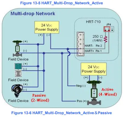
Q08 : How to integrate Active and Passive HART devices in multi-drop network ?
- If there are more than 7 HART devices in the HART network, users need to disable the internal resistor (250 Ohm, 1/4W) of HRT-711 (adjust JP4 to be pin2 and pin3, refer to the section 2.6 for detailed). Then add the external resistor (250 Ohm, 1W) in HART network.
- The HART wiring of the Active and Passive HART devices, please refer the following figure.

Q09 : How to integrate multiple HRT-711 modules in the same project ?
[ Case Example ]
1. A user wants to integrate 20 HART devices (Ultrasonic Water Level) in the same project via Modbus/TCP or Modbus/UDP communication and HART wiring will be point to point.
[ Solution ]
< Hardware >
1. We suggest the user to use 20 HRT-711 modules to connect to 20 HART devices with point to point wiring.
< Software >
1. The HRT-711 is a Modbus/TCP and Modbus/UDP server, if users need to multiple HRT-711, users follow section 5.4 to configure the Ethernet. After configuring HRT-711’s Ethernet and connecting to Ethernet switch, all HRT-711 can be identified by the IP address.
Q10 : How to integrate HART communication device with RS-232 hardware interface ?
[ Case Example ]
1. A user wants to integrate HART communication device (Flowmeter, Mobrey MCU900) with RS-232 hardware interface.
[ Solution ]
< Hardware >
1. We suggest the user to use HRT-711 and I-7570 to do that and the wiring for this case.

< Software >
1. Please refer to the steps in the Q01, Q02 and Q03 of HRT-711 FAQ to integrate HART device information to SCADA.
Q11 : How to add the HART Device-Specific command to HRT-711 ?
[ Case Example ]
1. An user wants to get the HART command No.149 data from Emerson 8800D HART device.
[ Solution ]
< Software >
- Users must get the HART Device-Specific command first. The HART command No.149 format of Emerson 8800D.

- Add the HART command No.149 to HRT-711.

- After the setting is finished, in the Device Configuration screen, please click the Save to Device button to save the parameters to HRT-711.

- Get the Modbus address for the HART command No.149 data.
(1) Open the “Address Map” screen and click the “UserCMD(149)” item.
[1] In the Modbus AO area, the light blue grid means the Modbus address for data sending.
[2] In the “Modbus AI” area, the light blue grid means the Modbus address for data receiving.
=> In the case, the HART command No.149 is used for reading data. Therefore, the light blue grid just show in “Modbus AI” area and the Modbus address for receiving data is from 0 to 2.

(2) Users can use the Modbus Function Code 4 and address from 0 to 2 to get the HART command No.149 data. (Ex: Request Cmd => 0x01 0x04 0x00 0x00 0x00 0x03)
Q12 : How to set HART device address by HRT-711 utility?
- Add the UserCMD(6) to HRT-711:
(1) Run HRT-711 Utility and connect to HRT-711.
(2) Open the Device Configuration page.
(3) Add UserCMD(6) and choose Manual option in Mode field.
(4) Click Save to Device button.
- Set HART device address and send the UserCMD(6):
(1) Open Device Information page.
(2) Right click on the UserCMD(6) item and choose the Basic Operation.
(In the demo, the command index is 0 for the UserCMD(6).
(3) Input the HART device address value and click the Send button.
(In the demo, HART device address will be set to be 2. Now the setting value is just saved in HRT-711 not sent out yet.) (4) Right click on the System item and choose the Basic Operation.
(5) After finishing the below settings, click Send Data button to send the UserCMD(6) to HART device.
[1] Auto Polling field => Disable
[2] Manual Trigger field => Enable
[3] Trigger Index of User Command field => Input 0 (UserCMD(6) Index)

- Now the HART device address should be set to be 2. Then please reboot HRT-711.
(After changing device address, please also remember to modify the device address in the Device Configuration)
Q13 : All kinds of HART network wiring ?
A13: (2015/10/26)
- The wiring of “Point to Point” :


- The wiring of “Multi-Drop”:

Q14 : Apply the same settings to the other HRT-711 rapidly ?
A14: (2015/12/21)
- Save HRT-711 settings to file.
(1) Run the HRT-711 utility, HG_Tool.
(2) In the “Device Configuration” page, click the “Save to File” button to save the current settings of HRT-711 to file.
- Load the settings from HRT-711 file to the other HRT-711 module.
(1) In the “Device Configuration”, click the “Load From File” button and choose the setting file of HRT-711. Then it will show all the settings in the HG_Tool. (2) Click the “Save to Device” button to set the settings to HRT-711 module.
Q15 : How to send HART command for writing ? (Ex: CMD19)
A15: (2015/12/23)
- Add the HART command for writing in HRT-711.
(The HART cmd 19 is used in the below example => Final Assembly Number)
(1) In the “Device Configuration” page, click the right button of mouse on the “HART Device 0” item and choose the “Add Command” option. (2) Input the value “19” in the “Command Num” field and choose the “Manual” option in the “Mode” field. Click the “OK” button to add the HART command 19 (Now the User Command Index is 0) and click the “Save to Device” button to save the current settings to HRT-711.
- Set the value for the HART writing command. (HART command not yet sent)
(1) There are three bytes parameters for HART command 19.
(2) For example, the value for these three bytes parameters is 11(0x0B), 22(0x16), 33(0x21) for writing, and the Modbus command will be as below.
=> 01 06 00 00 0B 16 0F 34
=> 01 06 00 01 21 00 C0 5A
(3) The below figure is the assigned value for writing in HART command 19 by using ModScan software for testing. (4) After sending the above Modbus command, users can check if these values have been set successfully via HG_Tool.
[1] In the “Device Information” page, click the right button of mouse on the “User CMD(19)” item and choose the “Advanced operation” option. [2] In the “I/O Data” page, click the “Update” button and it will show the value for sending of UserCMD in the corresponding byte address in the “Output Data” area. Users can see these values of “11”, “22” and “33” been set successfully.
- Trig the HRT-711 to send the UserCMD0 (HART command 19).
(1) Stop the original HART polling command and send the UserCMD0.
The Modbus command will be as below.
=> 01 06 01 F5 00 00 98 04
=> 01 06 01 F6 01 00 69 94
[1] 00 : Stop all the original HART polling command.
[2] 00 : Set the no. of UserCMD for sending.
[3] 01 : Trig to send the UserCMD and it needs the different value every time.
(Ex: the next value will be 2, 3, 4 …)
=> Now the UserCMD0 (HART command 19) has been sent.
(2) Recover the original HART polling command.
The Modbus command will be as below.
=> 01 06 01 F5 01 00 99 94
[1] 01 : recover all the original HART polling command.
Q17 : How to get HART command 48 information ?
A17: (2016/10/07)
- Add HART CMD 48 to HRT-711.

- In the “Device Configuration” screen, click the “Save to Device” button to save the settings to HRT-711.

- Get HART CMD48 data via Modbus.
(1) Open the “Address Map” screen and click the “UserCMD(48)“ item. In the “Modbus AI” area, it will show the Modbus data address of UserCMD(48) with blue grid.
=> The response data length of HART CMD 48 will be 27Bytes (ResCode(2) and ResData(25)). Therefore, it will occupy 14 WORD Modbus address as below address 0~13. Figure 17-3 The modbus address occpied by UserCMD(48)
(2) Using Modbus Function Code 4 and address 0~13 to get the data of HART CMD 48.

Q18 : How to send HART “Burst Mode” CMD? (CMD108/109)
A18: (2017/01/09)
- The below is the description for HART burst command function.
(1) HART CMD 108 (Write Burst Mode Command Number)
=>Used to set the response HART command no. when HART device burst mode is enabled.
(2) HART CMD 109 (Burst Mode Control)
=>Used to set HART device burst mode enabled or disabled. - Add HART CMD 108 and 109 to HRT-711
(1) In the “Device Configuration” page, click the right button of mouse on the “HART Device 0” item and choose the “Add Command” option.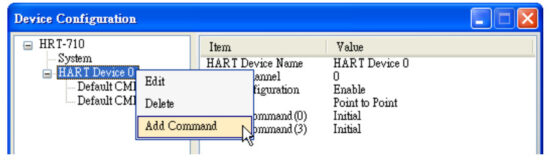 (2) [1] Input the value “108” in the “Command Num” field and choose the “Manual” option in the “Mode” field. Click the “OK” button to add the HART command 108 (Now the User Command Index is 0)
[2] Input the value “109” in the “Command Num” field and choose the “Manual” option in the “Mode” field. Click the “OK” button to add the HART command 109 (Now the User Command Index is 1)
[3] Click the “Save to Device” button to save the current settings to HRT-711.

- Set the value for the HART CMD 108. (HART CMD 108 sent not yet)
(1) There are one byte parameter in HART CMD 108.
(Ex: The writing value 3(0x03)=> It means that when HART device is in the burst mode, HART CMD 3 data will be sent from HART device automatically and periodically.
(2) Modbus command for the function is as below.
=> 01 06 00 00 03 00 89 3A
(3) After sending the above Modbus command, users can check if these values have been set successfully via HG_Tool..
[1] In the “Device Information” page, click the right button of mouse on the “User CMD(108)” item and choose the “Advanced operation” option. [2] In the “I/O Data” page, click the “Update” button and it will show the value for sending of UserCMD in the corresponding byte address in the “Output Data” area. Users can see the value of “3” been set successfully.
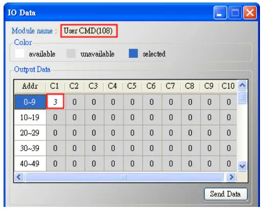
- Trig the HRT-711 to send the UserCMD0 (HART command 108)
(1) Stop the original HART polling command and send the UserCMD0.
The Modbus command will be as below.
=> 01 06 01 F5 00 00 98 04
=> 01 06 01 F6 01 00 69 94
[1] 00 : Stop all the original HART polling command.
[2] 00 : Set the UserCMD no. for sending.
[3] 01 : Trig to send the UserCMD and it needs the different value every time.
(Ex: the next value will be 2, 3, 4 …)
=> Now the UserCMD0 (HART command 108) has been sent. - Set the value for the HART CMD 109. (HART CMD 109 sent not yet)
(1) There are one byte parameter in HART CMD 109.
[1] The writing value 1(0x01)=> It means HART device burst mode will be enabled.
[2] The writing value 0(0x00)=> It means HART device burst mode will be disabled.
(2) Modbus command for the function is as below.
[1]Enable Burst mode => 01 06 00 01 01 00 D9 9A
[2]Disable Burst mode => 01 06 00 01 00 00 D8 0A
(3) After sending the above Modbus command, users can check if these values have been set successfully via HG_Tool..
[1] In the “Device Information” page, click the right button of mouse on the “User CMD(109)” item and choose the “Advanced operation” option. [2] In the “I/O Data” page, click the “Update” button and it will show the value for sending of UserCMD in the corresponding byte address in the “Output Data” area. Users can see the value of “1” been set successfully.
- Trig the HRT-711 to send the UserCMD1 (HART command 109)
(1) Stop the original HART polling command and send the UserCMD1.
The Modbus command will be as below.
=> 01 06 01 F5 00 00 98 04
=> 01 06 01 F6 02 01 A8 A4
[1] 00 : Stop all the original HART polling command.
[2] 01 : Set the UserCMD no. for sending.
[3] 02 : Trig to send the UserCMD and it needs the different value every time.
(Ex: the next value will be 3, 4, 5 …)
=> Now the UserCMD1 (HART command 109) has been sent. - Recover the original HART polling command.
(1) The Modbus command will be as below.
=> 01 06 01 F5 01 00 99 94
[1] 01 : recover all the original HART polling command.
Q19 : How to reset totalizer value by sending Device-Specific command?
A19: (2017/11/28)
[ Case Example]
- A user wants to use HRT-711 to reset the totalizer value from instrument KROHNE ESK4 by sending HART command 137.
[ Solution ] 1. Users must get the HART Device-Specific command first. The HART command No.137 format of KROHNE ESK4
- Add UserCMD CMD137 of ROHNE ESK4 to HRT-711:

- After finished settings, click “Save to Device” button in Device Configuration to save all the settings.

- Trig the HRT-711 to send UserCMD0 (HART command 137)。
(1) Stop the original HART polling command and send UserCMD0
(2) The Modbus command will be as below:
=> 01 06 01 F5 00 00 98 04
=> 01 10 01 F6 01 00 69 94
[1] 00 : Stop all the original HART polling command
[2] 00 : Set the no. of UserCMD for sending
[3] 01 : Trig to send the UserCMD and it needs the different value every time. (Ex: the next value will be 2,3,4 …)
=> Now the UserCMD0 (HART command 137) - Recover the original HART polling command
(1) The Modbus command will be as below:
=> 01 06 01 F5 01 00 99 94
[1] 01 : recover all the original HART polling command
Q20 : How to read total-flow data from flow-meter?
A20: (2018/04/10)
[ Case Example]
- A user wants to use HRT-711 to read the total-flow value from SIEMENS instrument FUS060.
[ Solution ]
1. According to the user manual of FUS060, device specific CMD130 is for reading total value and there are 3 values with 4 bytes length each, so the total data length is 3*4 = 12 bytes Adding device specific command to HG_Tool requires to enter in and out data bytes, the in and out data here should include a 2 bytes response code.
- After adding the CMD130, please check whether it works properly by checking from the Advanced operation from Device Information and analyse with the IEEE754 Converter provided by HG_Tool Format Translation function.

- After making sure the settings in HG_Tool are all properly done, Modbus tools can be used to testify. ModScan has been used as an example here:
(1) HRT-711 records device specific command data from Modbus address 0~499
| MB_Addr (HEX) | MB_Addr (Decimal) | Description |
| [ User CMD Data ] | ||
| 0-1F3 | 0-499 | “User CMD” data |
(2) Because ModScan is a 1-based (instead of starting from 0) software, so the address should be from 1~500
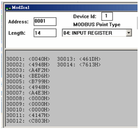
(3) The first 2 Bytes are response code, so the data starts from address 2

Q21 : HART communication update period calculation and adjustment
A21: (2018/08/02)
- HART communications update period calculation :
Settings shown as below will be used as example: (HRT-711 with 2 HART devices)
1) HRT-711 parameters setting as below:
[1] HRT-711 sends CMD0 and CMD3 to both HART instruments
[2] CMD0 sets as Init mode, CMD3 sets as Polling mode
[3] Cmd Interval sets as 1000 ms 2) The update period of all HART instruments’ data in HRT-711 is:
[1] Init commands (CMD0) communication time:
HRT-711 will send CMD0 to short frame address from 0 and stops until finds all devices.
As the settings shown above, Device 0 and 1 has short frame address of 1 and 2, so CMD0 will be sent 3 times. Communication time is: 3*1000 = 3000 ms
Note: Because CMD0 is Init command, it will only be executed when HRT-711 booted up, so it does not affect HART communication update period.
[2] Polling commands (e.g. CMD3) communication time:
HRT-711 will sends Polling commands to each HART device sequentially. As the settings shown above, there are total of 2 HART instruments and only 1 Polling command (CMD3) is required to be sent for each device. Therefore communication time is: 2(Devices) * 1(Polling CMD) * 1000(ms) = 2000 ms
=>Conclusion: HART communication update period is the total time taken to send
all Polling commands. So the update period here is 2000 ms - HART communication update period adjustment :
1) Shorten HART communication update period
[1] Delete unnecessary HART polling commands
The default settings of HART gateway contains 1 HART device and multiple HART commands, shown as below In order to shorten HART device update period, it is recommended to delete the whole device and then add a new device setting. (Refer to FAQ Q01)
[2] Shorten HART command interval
Right click on the System item and select Edit, reduce the time for Cmd Interval, 500 ms is suggested to be the minimum command interval. 2) The communication update period for HRT-711 to collect all devices data is: 2(Devices) * 1(Polling CMD) * 500(ms) = 1000 ms
Q22 : Integrate HART communication to traditional AI structure
A22: (2018/10/29)
- The existing AI loop system:
1) Device analog signal collected by AI module
- Integrating HART communication to collect more HART device information:
1) Integrating HART Gateway to the existing system, new system as follow:
2) Switch off HART Gateway built-in resistor and parallel connecting to AI module => Additional HART communication function integrated to existing system
Note: The HART loop resistor in HRT-711 needs to be set disabled.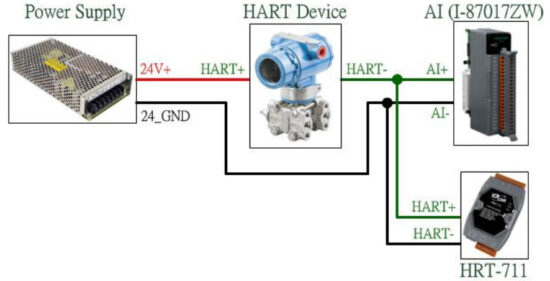
- If AI readings of the initial system get disturbed after HART gateway added:
1) Using HART Filter (HRT-370) to split HART digital signal and AI analog signal => new system as follow:
Note: The HART loop resistor in HRT-711 needs to be set disabled.
Q23 : HART Multi-drop mode precautions
A23: (2018/10/29)
Hardware:
- HART devices address must set in between 1~15 and no repeated.
1) Please first set the HART address for each HART device one by one, then adding all to the HART Multi-drop loop. - Wiring for HART Multi-drop mode is as follow:

- Start building structure from 2 HART devices
1) To avoid situation that when error occurs and not knowing how to debug, it is recommended to start building structure with only 2 devices and adding 1 more device at a time if no error occurs until all devices been added. - Make sure the HART loop resistance is 250Ω
1) Please measure if the resistance is around 250Ω in between Module’s (ex. HRT-710) HART+ / HART- - Choose HART loop resistor when connecting to 7 or more HART devices
1) HRT-710 and HRT-711 with hardware version earlier than V1.30:
When connecting more than 7 HART devices, built-in resistor (250Ω, 1/4W) may be burned, therefore suggesting use an external resistor (250Ω, 1W)
2) HRT-710 and HRT-711 with hardware version from V1.30 and later:
Module upgraded built-in resistor to 250Ω(2W), therefore no need to worry => HRT-310 designed to use built-in resistor of 250Ω (2W) at first place, therefore no need to worry about this issue - Check the voltage in between HART device (Be aware of voltage drop)
When connecting more HART devices, the voltage available between devices + / – drops and devices may not be able to turned on. Example as follow:
In Multi-drop mode, every HART device provides extra 4mA to HART loop, if customer uses a 24V power supply, the voltage between HART devices should be as follow:
1) Connecting 1 HART device:
Loop current: 4mA; Loop resistance: 250Ω=> Voltage drop between resistor: 1V; therefore voltage left for devices: 24V-1V=23V
2) Connecting 10 HART devices:
Loop current: 40mA; Loop resistance: 250Ω=> Voltage drop between resistor: 10V; therefore voltage left for devices: 24V-10V=14V
3) Connecting 11 HART devices:
Loop current: 44mA; Loop resistance: 250Ω=> Voltage drop between resistor: 11V; therefore voltage left for devices: 24V-1V=13V
(If device needs 14V or above voltage in order to be turned on, then HART communication failed)
=> When connecting to multi HART devices, all HART devices can’t be communicated. (For example, when connecting to 9 HART devices, HART communication is ok. But connecting to 10 HART devices, all HART devices can’t be communicated.) Please follow the below method to improve the problem.
< Method 1: Adopt the external resistor > (refer to section 2.3.4 for HART wiring)
[1] Disable the internal resistor of HRT-310 / HRT-710. (refer to section 2.6)
[2] Adopt the external resistor 150 ohm or 100 ohm for testing. (It is used to reduce the voltage drop in the loop resistor.)
< Method 2: Adopt the power supply with higher voltage >
[1] Adopt the power supply more than 24V (like 28V or 36V).
Software Configuration (HG_Tool):
- Set Module Address between 1~15 in Module Configuration.

Q24 : HART communication distance issues
A24: (2019/02/23)
- When installing HART network, communication distance needs to be considered. Please refer to below table for information about cable capacitance and length
Cable Capacitance – pf/ft (pf/m)
Cable Length — fee (meters)No. Network Devices 20 pf/ft
(65 pf/m)30 pf/ft
(95 pf/m)50 pf/ft
(160 pf/m)70 pf/ft
(225 pf/m)1 9,000 ft
(2,769 m)6,500 ft
(2,000 m)4,200 ft
(1,292 m)3,200 ft
(985 m)5 8,000 ft
(2,462 m)5,900 ft
(1,815 m)3,700 ft
(1,138 m)2,900 ft
(892 m)10 7,000 ft
(2,154 m)5,200 ft
(1,600 m)3,300 ft
(1,015 m)2,500 ft
(769 m)15 6,000 ft
(1,846 m)4,600 ft
(1,415 m)2,900 ft
(892 m)2,300 ft
(708 m)Source:
https://www.fieldcommgroup.org/sites/default/files/technologies/hart/ApplicationGuide_r7.1.pdf - If communication distance needs to be extended, please try following methods:
(1) Use Fiber to extend HART communication distance HRT-227CS is HART to Single-Mode Fiber converter, specially designed to extend HART communication distance. For more information, please refer to:
HRT-227CS user manual: ftp://ftp.icpdas.com/pub/cd/fieldbus_cd/hart/converter/hrt-227cs/manual/
(2) Use Fiber to extend RS-485 communication distance I-2541 and I-2542 series are RS-232/ 422/ 485 to Single-Mode Fiber converters, specially designed to extend Serial communication distance. For more information, please refer to:
I-2541 user manual: http://www.icpdas.com/download/converter/manual/net-i2541.pdf
I-2542 series user manual: http://www.icpdas.com/root/product/solutions/datasheet/industrial_communication/I-2542-Release%20Note_V1%2000.pdf
(3) Use Fiber to extend Ethernet communication distance
ICP DAS provides various Ethernet to Fiber switch, below is an example of using NS-205F and NS-209F Ethernet switch to extend communication distance To find suitable Ethernet & Fiber switch, please check from: http://www.icpdas.com/root/product/solutions/industrial_ethernet_switch/switch_selection.html#a
(4) Use Ethernet Switch to extend Ethernet communication distance Similar to previous method, instead of using Fiber, simple Ethernet switch can also extend the communication distance
To find suitable Ethernet switch, please check from: http://www.icpdas.com/root/product/solutions/industrial_ethernet_switch/switch_selection.html#a
Q25:Using Through Mode of HG_Tool to Stop Burst Mode of HART Device
A25: (2019/08/28)
- Run the HG_Tool and connect to HRT-711.
(1) Disable all the Polling command. (2) Open the “Through Mode” and send HART CMD0 to get the “Long Frame Address” of HART device.
[1] HART CMD0 : FF FF FF FF FF 02 80 00 00
[2] Long Frame Address : 1A 0B 50 EB CD (As the below figure)
(3) Configure HART command 109 and send it to disable the burst mode of HART device.
[1] HART CMD 109 => Ex : FF FF FF FF FF 82 DA 0B 50 EB CD 6D 01 00
<1> FF FF FF FF FF : Preamble
<2> 82 : Delimiter (0x02 need to add 0x80 = 0x82)
<3> DA 0B 50 EB CD : Long Frame Address (Different from every HART device) (0x1A need to add 0xC0 = 0xDA)
<4> 6D : HART command no. (0x6D = 109)
<5> 01 : Byte Count (HART command parameter byte)
<6> 00 : Data (HART command parameter content. 00 for )
Q26:How to use the In_Offset field of the UserCMD ?
A25: (2020/08/19)
[ Example ]
2. A user wants to use HRT-711 to read the float data from instrument Endress-Hauser Promass F300 by sending HART command 158. (The float data doesn’t arranged in two WORD of Modbus address)。
[ Solution ]
3. Run the example, users need to update the firmware of HRT-711 to be v1.03 and use HG_Tool_v1.5.0.

4. The format of HART command 158 is as below.
(1) The start byte of the response float data is in byte3.

5. Add the UserCMD of HART command 158 to HRT-711.

(1) Owing to the start byte of the response float data is byte3, so in the “In_Offset” field, users can fill with 3 to ignore HART response data byte0, 1, and 2. Then the response float data can be shown in the Modbus address easily.

(2) In ”System Edit” page, please set the ”W&B” in the Swap Mode field.

6. After finished the settings, click “Save to Device” button in Device Configuration to save all the settings.
7. Trig the HRT-711 to send UserCMD0 (HART command 158). (refer to the steps of FAQ15)
8. Get the response data of HART command 158 via HG_Tool.
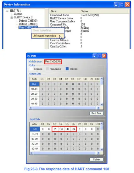
9. Get the response data of HART command 158 via modscan tool.
(1) The Modbus first WORD data: the response code of HART command 158.
(2) The Modbus second and third WORD data: the float data of HART command 158.

Q27:How to use “Listen Only” function to get HART data?
A27: (2020/08/20)
[ Example ]
[1] A user wants to get HART device data (like HART command3) in another PC using Modbus/TCP in the original HART network without interfering the original HART communication.
[2] A user wants to get HART device data (like HART command3) when HART device works in the burst mode. (First the user needs to know which HART command sent by HART device in the burst mode. In general, HART command 3 will be burst command.)
=> The “Listen Only” function can be used in these two above examples.
[ Solution ]
- The HART “Listen Only” function had been supported in HRT-711 firmware v1.03 or newer. In the “Listen Only” mode, HRT-711 doesn’t send any HART command and just receives and analyzes HART command. Then users can get HART device data via Modbus/TCP smoothly.
- Case-1: ( There is just only one HART device in HART network )
(1) Using HDS (HART Device Simulator) software to set HART command 3 and 158 data as the below figure for HART device. (2) Add HART command 3 and 158 to HRT-711.
 (2) In the ”System Edit” page, Set ”Auto Polling” to be ”Disable”(HRT-711 will not send HART command) and set the “Swap Mode” to be ”W&B”.
 (3) After finished the settings, click “Save to Device” button in Device Configuration to save all the settings.
(4) Get the response data of HART command 3 and 158 via Modscan tool.
- Case-2: ( There two HART devices in HART network )
(1) Using HDS (HART Device Simulator) software to set HART device address 1 and address 3 and HART command 3 data as the below figure for these two HART devices. (2) Add HART device with address 1 and address 3 to HRT-711.
[1] Users need to un-check the “Auto Get Unique ID” checkbox and fill with the long frame address of HART device. (2) In the ”System Edit” page, Set ”Auto Polling” to be ”Disable”(HRT-711 will not send HART command) and set the “Swap Mode” to be ”W&B”.
 (3) After finished the settings, click “Save to Device” button in Device Configuration to save all the settings.
(4) Get the response data of HART command 3 of these two HART devices via Modscan tool.
Q28:Using multiple HART CMD33 in “Listen Only” mode ?
A28: (2023/01/03)
[ Example ]
Owing to the different data of Request Data in HART CMD33, the response data will be different in HART CMD33. If users want to put the different response data in the corresponding Modbus address, users can add the multiple HART CMD33 to do that (need to set the data in the ”Default Output Data” page). The below will use three HART CMD33 for example. (The function is supported in firmware v1.15 or above)
- According the steps of FAQ Q27, set HRT-711 to be “Listen Only” mode.
- Add three HART command 33。


- Open the ”Default Output Data” page.

- Set the request data of these three HART command 33.
[1] The first UserCMD(33) – Red: 4 bytes are all 0.
[2] The second UserCMD(33) – Pink: The first byte is 1 and the others are all 0.
[3] The third UserCMD(33) – Blue: The first byte is 2 and the others are all 0.
=> After finish, click the ”Save to Device” button.
- When HRT-710/310 receives HART request command 33, it will compare the “Request Data” value and if match, it will save HART response command 33 data to the correct Modbus address. (If no match, it will ignore the HART command 33 data)
[1] In the ”Device Information” page, open the ”Advanced operation” of UserCMD(33). [2] Using ”Modscan” software to get these three HART command 33 data.
(The data format in Modscan is hex and in “IO Data” page is decimal.)
Q30:How to get HART command 9 information?
A30: (2023/10/11)
- The request data format of HART command 9 is as Figure 30-1.

- The response data format of HART command 9 is as Figure 30-2.
 Figure 30-2
[1] When the request data length is 1, the response data length will be 13. The response data format will be “Extended device status (1B)” + “Slot 0 Data (8B)” + “Time stamp (4B)”.
[2] When the request data length is 2, the response data length will be 21. The response data format will be “Extended device status (1B)” + “Slot 0 Data (8B)” + “Slot 1 Data (8B)” + “Time stamp (4B)”.
…
[8] When the request data length is 8, the response data length will be 69. The response data format will be “Extended device status (1B)” + “Slot 0~7 Data (64B)” + “Time stamp (4B)”.
=> If HART command version of HART device is lower than v7.0, then the time stamp (4B) of the response data should be removed. - The below example adopts that HART command version of HART device is v7.0 and the request data length is 2 for HART command 9. So the response data length will be 21.
[1] In the HG_Tool, add command number 9. The “In Size” and “Out Size” fields fill in 23 and 2 (The data length of the “In Size” field should include the response code (2B) like Figure 30-4.) [2] Click the “Save to Device” button to save the settings to HRT-710 like Figure 30-5.
 [3] In the “Device Information” of HG_Tool, right click the “User CMD9” and choose the “Advanced operation” option (like Figure 30-6) to show the received data of CMD9 (like Figure 30-7).
 [4] In Figure 30-8, using HART converter (like I-7567) with HC_Tool software to read HART command 9 data of HART device. The data will be the same with Figure 30-7 except the data of Time Stamp.
 [5] Get HART command 9 data via Modbus communication:
<1> In the “Address Map” screen, click the “UserCMD(9)” item. In the “Modbus AI” area, the blue grid will be the address of the received data of UserCMD(9) like Figure 30-9. In the example, it needs 23 bytes (response code (2B) + response data (21B)) for HART command 9.
Therefore, it will occupy 12 modbus address from 0 to 11.
<2> In Figure 30-10, they are the Modbus data received from address 0~11 (30001~30012) by using Modscan software.
Q31:Integrate HART device with burst mode ?
A31: (2024/03/07)
[ Example ]
[1] A user wants to get two HART device data.
<1> One HART device works in the burst mode.
<2> Another HART device works in the send/receive mode.
[ Note ]
[1] Need to know the long frame address and which HART command sent by HART device in the burst mode.
[ Solution ]
- Set these two short address of HART devices to be 1 and 2.
[1] The long address of HART device 1 is 0x1A 0B 50 EB CD and the burst mode command no. is command 3.
[2] The HART device 2 is in the send/receive mode.
- Add these two HART devices with address 1 and 2 to HRT-711.
(1) In the ”Module Edit” page, add these two HART devices. (2) In the ”System Edit” page, set the “Swap Mode” to be ”W&B”.
 (3) After finished the settings, in “Device Configuration” page, click “Save to Device” button to save all the settings to HRT-711.
 - Get these two HART device data.
(1) Get HART command 3 data of these two HART devices by using HG_Tool. (2) Get HART command 3 data of these two HART devices by using Modscan software.
(HART command 3 data are all the same in HG_Tool and Modscan.)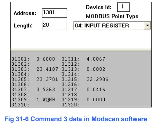
Q101 : The whole configuration process of HRT-711 ?
A101: (2016/02/19)
- Set the network parameters of HRT-711 (Ex : IP / Mask / Gateway)。
(1) Connect the Ethernet port between PC and HRT-711.
(2) Run the “HRT-711 Utility” and click the “Ethernet” item. (3) Click the “Search Servers” button and it will search all the HRT-711 modules automatically.
 (4) Choose the “HRT-711” item and click the “Configuratino (UDP)” button and users can set the network parameters of HRT-711. Then click the “OK” button to save the settings.
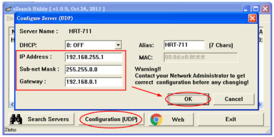
- Run the HRT-711 utility to connect to HRT-711 via RS-232 for HART configuration.
(1) Using the CA-0910 cable (3 pin RS-232, TxD/RxD/GND) included in the HRT-711 product.
Connect the TXD / RXD / GND pins between CA-0910 and HRT-711. (Wiring : TXD to TXD, RXD to RXD, GND to GND) (Note : The RS-232 pin assignment of HRT-711, the left pin1 is reserved and then the left pin2, 3 and 4 will be TXD, RxD and GND.)
 (2)Run the “HRT-711 Utility” and click the “HART” item.
 (3) Follow the instruction of the figure to set the “Dip Switch” in the back of HRT-711 to be “Init” and then reboot HRT-711.
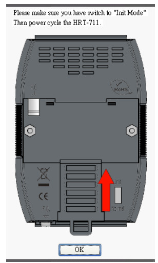 (4) Click the “Communication Settings” item.
[1] Device : choose the “HRT-711”.
[2] Port Num : choose the ComPort no. of PC.
=> After finish, click the “OK” button. (5) Click the “Connect” button. After about 5 seconds, if the green light is “ON” of the traffic light in the left-top corner of HRT-711 utility, it means the connection is successful. Then users can configure the HRT-711 for HART devices.

- Add the HART devices to HRT-711.
(1) The detailed steps, please refer to the “Q01 : How to add HART devices to HRT-711 ?” of FAQ. - Check if HRT-711 gets the HART device data correctly.
(1) The detailed steps, please refer to the “Q02 : How to make sure that HRT-711 gets the HART device data correctly ?” of FAQ.
=> If the communication between HRT-711 and HART devices is failed, the ERR LED will flash. If the communication is ok, the ERR LED will be OFF. - Get the HART device data via Modbus/TCP or Modbus/UDP.
(1) Set the “Dip Switch” in the back of HRT-711 to be “Normal” and then reboot HRT-711.
(2) Refer to the detailed steps of the “Q03 : How to map HART device CMD(3) data directly to SCADA or HMI ?” of FAQ.
Q102:How to configure the parameters via Ethernet on HRT-711 ?
A102:(2021/11/24)
- Users can use ICP DAS MB/TCP to MB/RTU gateway to do that。
(1) The below adopts tGW-724 for example. (https://www.icpdas.com/en/product/tGW-724) (2) About the detailed settings in tGW-724, please refer to the chapter – 6.4 TCP Client Mode.
https://www.icpdas.com/en/download/show.php?num=2375&model=tGW-724
[1] The above setting is used to set tGW-724 to be a MB/TCP Client and connect to HRT-711(MB/TCP server) automatically. - Run “HG_Tool” and click the “Communication Settings” item to set the COM Port, Baud Rate …etc. and these settings should be the same as the port settings in tGW-724. Then HG_Tool can connect to HRT-711 successfully and set parameters via HRT-711 Ethernet.

Q103:The Max. MB/TCP client connection number in HRT-711 ?
(2021/11/24)
A103:HRT-711 supports the max. MB/TCP client connection number to be 32. When the total connection number in HRT-711 exceeds 32, then no more MB/TCP client can connect to HRT-711 successfully.
Q104:How to configure IP / Mask / Gateway of HRT-711 via web ?
(2023/05/15)
A104:HRT-711 provides the built-in web server for module Ethernet parameter setting. Please follow the below steps.
[ Step 1: Type “IP Address” in the Web Browser & Set the new Password ]
HRT-711 supports many kinds of web browser like Mozilla, Firefox, Google Chrome and Microsoft Edge etc. for parameter setting. The factory default IP address and password of HRT-711 is “192.168.255.1” and “admin”. When connecting to web server of HRT-711 in the first time, users must set the new password. Please type “admin” in the “Current password” field and then set the new password for HRT-711.

[ Step 2: Type the new “Password” in Log-In screen ]
Type the new password in the “Login password” field and click “Submit” button to log in.

[ Step 3: Set the IP / Mask / Gateway ]
After log in success, it will show the HRT-711 information. Click the “Network Setting” option, and then users can set the IP / Mask / Gateway. After setting finished, please click the “Update Settings” button to save the settings in HRT-711.

Appendix A HART Command
In this chapter, the following lists are the HART universal command format.
Command 0:Read Unique Identifier
| Request Data Bytes | 0 | ||
| Response Data Bytes | 2 + 12 = 14 | ||
| Byte Index | Format | Desciption | |
| 0 | Uint8 | Response Code 1 | |
| 1 | Uint8 | Response Code 2 | |
| 2 | Uint8 | 254 | |
| 3 | Uint8 | Manufacturer ID | |
| 4 | Uint8 | Manufacturer’s device ID | |
| 5 | Uint8 | Number of preambles needed in the request | |
| 6 | Uint8 | Command set revision number | |
| 7 | Uint8 | Transmitter specific revision code | |
| 8 | Uint8 | Software revision | |
| 9 | Uint8 | Hardware revision | |
| 10 | Uint8 | Flags | |
| 11~13 | Uint24 | Device ID number (MSB first) | |
Command 1:Read Primary Variable
| Request Data Bytes | 0 | ||
| Response Data Bytes | 2 + 5 = 7 | ||
| Byte Index | Format | Desciption | |
| 0 | Uint8 | Response Code 1 | |
| 1 | Uint8 | Response Code 2 | |
| 2 | Uint8 | Unit code | |
| 3~6 | Float | Primary Variable | |
Command 2:Read P.V. Current and Percentage of Range
| Request Data Bytes | 0 | ||
| Response Data Bytes | 2 + 8 = 10 | ||
| Byte Index | Format | Desciption | |
| 0 | Uint8 | Response Code 1 | |
| 1 | Uint8 | Response Code 2 | |
| 2~5 | Float | Primary Variable Current | |
| 6~9 | Float | Primary Variable Percentage of Range | |
Command 3:Read Dynamic Variables and P.V. Current
| Request Data Bytes | 0 | ||
| Response Data Bytes | 2 + 24 = 26 | ||
| Byte Index | Format | Desciption | |
| 0 | Uint8 | Response Code 1 | |
| 1 | Uint8 | Response Code 2 | |
| 2~5 | Float | Primary Variable Current | |
| 6 | Uint8 | Primary Variable Unit code | |
| 7~10 | Float | Primary Variable | |
| 11 | Uint8 | Secondary Variable Unit code | |
| 12~15 | Float | Secondary Variable | |
| 16 | Uint8 | Tertiary Variable Unit code | |
| 17~20 | Float | Tertiary Variable | |
| 21 | Uint8 | Quaternary Variable Unit code | |
| 22~25 | Float | Quaternary Variable | |
Command 6:Write Polling Address
| Request Data Bytes | 1 | ||
| Byte Index | Format | Desciption | |
| 0 | Uint8 | Polling Address | |
| Response Data Bytes | 2 + 1 = 3 | ||
| Byte Index | Format | Desciption | |
| 0 | Uint8 | Response Code 1 | |
| 1 | Uint8 | Response Code 2 | |
| 2 | Uint8 | Polling Address | |
Command 11:Read Unique Identifier Associated with TAG
| Request Data Bytes | 6 | ||
| Byte Index | Format | Desciption | |
| 0~5 | PA6 | TAG Name | |
| Response Data Bytes | 2 + 12 = 14 | ||
| Byte Index | Format | Desciption | |
| 0 | Uint8 | Response Code 1 | |
| 1 | Uint8 | Response Code 2 | |
| 2 | Uint8 | 254 | |
| 3 | Uint8 | Manufacturer ID | |
| 4 | Uint8 | Manufacturer’s device ID | |
| 5 | Uint8 | Number of preambles needed in the request | |
| 6 | Uint8 | Command set revision number | |
| 7 | Uint8 | Transmitter specific revision code | |
| 8 | Uint8 | Software revision | |
| 9 | Uint8 | Hardware revision | |
| 10 | Uint8 | Flags | |
| 11~13 | Uint24 | Device ID number (MSB first) | |
Command 12:Read Message
| Request Data Bytes | 0 | ||
| Response Data Bytes | 2 + 24 = 26 | ||
| Byte Index | Format | Desciption | |
| 0 | Uint8 | Response Code 1 | |
| 1 | Uint8 | Response Code 2 | |
| 2~25 | PA24 | Message | |
Command 13:Read Tag, Descriptor, Date
| Request Data Bytes | 0 | ||
| Response Data Bytes | 2 + 21 = 23 | ||
| Byte Index | Format | Desciption | |
| 0 | Uint8 | Response Code 1 | |
| 1 | Uint8 | Response Code 2 | |
| 2~7 | PA6 | TAG Name | |
| 8~19 | PA12 | Descriptor |
| 20 | Uint8 | Day of month |
| 21 | Uint8 | Month of year |
| 22 | Uint8 | Year as offset to 1900 |
Command 14:Read Primary Variable Sensor Information
| Request Data Bytes | 0 | ||
| Response Data Bytes | 2 + 16 = 18 | ||
| Byte Index | Format | Desciption | |
| 0 | Uint8 | Response Code 1 | |
| 1 | Uint8 | Response Code 2 | |
| 2~4 | Uint24 | Sensor Serial Number (MSB first) | |
| 5 | Uint8 | Sensor limits unit | |
| 6~9 | Float | Upper sensor limit | |
| 10~13 | Float | Lower sensor limit | |
| 14~17 | Float | Minimum span | |
Command 15:Read Primary Variable Output Information
| Request Data Bytes | 0 | ||
| Response Data Bytes | 2 + 17 = 19 | ||
| Byte Index | Format | Desciption | |
| 0 | Uint8 | Response Code 1 | |
| 1 | Uint8 | Response Code 2 | |
| 2 | Uint8 | Alarm select code | |
| 3 | Uint8 | Transfer function code | |
| 4 | Uint8 | PV range value unit code | |
| 5~8 | Float | Upper range value | |
| 9~12 | Float | Lower range value | |
| 13~16 | Float | Damping value | |
| 17 | Uint8 | Write protect code | |
| 18 | Uint8 | Private label distribution code | |
Command 16:Read Final Assembly Number
| Request Data Bytes | 0 | ||
| Response Data Bytes | 2 + 3 = 5 | ||
| Byte Index | Format | Desciption | |
| 0 | Uint8 | Response Code 1 | |
| 1 | Uint8 | Response Code 2 | |
| 2~4 | Uint24 | Final assembly number (MSB first) | |
Command 17:Write Message
| Request Data Bytes | 24 | ||
| Byte Index | Format | Desciption | |
| 0~23 | PA24 | Message | |
| Response Data Bytes | 2 + 24 = 26 | ||
| Byte Index | Format | Desciption | |
| 0 | Uint8 | Response Code 1 | |
| 1 | Uint8 | Response Code 2 | |
| 2~25 | PA24 | Message | |
Command 18:Write Tag, Descriptor, Date
| Request Data Bytes | 21 | ||
| Byte Index | Format | Desciption | |
| 0~5 | PA6 | TAG Name | |
| 6~17 | PA12 | Descriptor | |
| 18 | Uint8 | Day of month | |
| 19 | Uint8 | Month of year | |
| 20 | Uint8 | Year as offset to 1900 | |
| Response Data Bytes | 2 + 21 = 23 | ||
| Byte Index | Format | Desciption | |
| 0 | Uint8 | Response Code 1 | |
| 1 | Uint8 | Response Code 2 | |
| 2~7 | PA6 | TAG Name | |
| 8~19 | PA12 | Descriptor | |
| 20 | Uint8 | Day of month | |
| 21 | Uint8 | Month of year |
| 22 | Uint8 | Year as offset to 1900 |
Command 19:Write Final Assembly Number
| Request Data Bytes | 3 | ||
| Byte Index | Format | Desciption | |
| 0~2 | Uint24 | Final assembly number (MSB first) | |
| Response Data Bytes | 2 + 3 = 5 | ||
| Byte Index | Format | Desciption | |
| 0 | Uint8 | Response Code 1 | |
| 1 | Uint8 | Response Code 2 | |
| 2~4 | Uint24 | Final assembly number (MSB first) | |
Appendix B Command Format
The HART data format of Modbus address is divided into the Normal and Simple format.
- Normal format
When read / write HART data by Modbus, the Modbus data format is HART standard command format. - Simple format
When read / write HART data by Modbus, the Modbus data format is simple format (omit the Response Code and Unit data). In this mode, the HMI or SCADA software can read or write HART data easily. Now, it only supports HART command number 1, 2 and 3.
The simple format of HART command
Command 1:(Read Primary Variable)
| Response Data Bytes | 4 | ||
| Byte Index | Format | Desciption | |
| 0~3 | Float | Primary Variable | |
Command 2:(Read P.V. Current and Percentage of Range)
| Response Data Bytes | 8 | ||
| Byte Index | Format | Desciption | |
| 0~3 | Float | Primary Variable Current | |
| 4~7 | Float | Primary Variable Percentage of Range | |
Command 3:(Read Dynamic Variables and P.V. Current)
| Response Data Bytes | 20 | ||
| Byte Index | Format | Desciption | |
| 0~3 | Float | Primary Variable Current | |
| 4~7 | Float | Primary Variable | |
| 8~11 | Float | Secondary Variable | |
| 12~15 | Float | Tertiary Variable | |
| 16~19 | Float | Quaternary Variable | |
Appendix C. Revision History
This chapter provides revision history information to this document.
| Revision | Date | Description |
| 1.14 | 2024/03/07 | Update FAQ Q01 / Q23 / Q27 Add FAQ Q28~31, Q104 |
| 1.13 | 2022/06/15 | Update FAQ Q28/Q29 and move to Q102/Q103 |
| 1.12 | 2022/04/19 | Update FAQ Q04 (Add “RevB” description) Update the structure of FAQ Q28 |
| 1.11 | 2021/11/24 | FAQ Q04 New alerts Add FAQ Q28, 29 |
| 1.10 | 2020/08/19 | Add Fig 2.3.2-4 Add FAQ Q26, 27 Add the “In Offset” field in the UserCMD setting |
| 1.09 | 2020/07/02 | Add FAQ Q24 / Q25 |
| 1.08 | 2018/10/29 | Add FAQ Q21 Add FAQ Q22 Add FAQ Q23 |
| 1.07 | 2018/05/22 | Modify FAQ Q15, 18, 19 with Modbus command FC06 FAQ Q04 add TCP firmware update section |
| 1.06 | 2018/04/10 | Add FAQ Q20 |
| 1.05 | 2017/12/20 | Add FAQ Q18, Q19 |
| 1.04 | 2017/05/10 | Add MB starting address explanation to FAQ Q03 |
| 1.03 | 2016/10/20 | Add FAQ17 Modify Firmware Update Process (Q04 of FAQ) |
| 1.02 | 2016/01/28 | Modbus/UDP server is also supported. |
| 1.01 | 2015/08/04 | Add FAQ chapter to this users’ manual |
| 1.00 | 2014/01/21 | First revision |
![]()
HRT-711 User Manual Version 1.15 Page:169
Copyright © 2017 ICP DAS Co., Ltd. All Rights Reserved E-mail: service@icpdas.com
Documents / Resources
 |
ICP DAS HRT-711 Modbus TCP to HART Gateway [pdf] User Manual HRT-711 Modbus TCP to HART Gateway, HRT-711, Modbus TCP to HART Gateway, HART Gateway, Gateway |