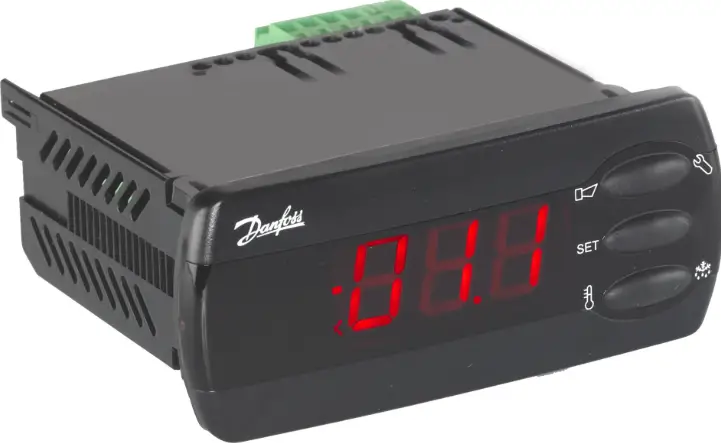
Danfoss AK-CC 210 Controller For Temperature Control
Especificacions
- Producte: Controller for temperature control AK-CC 210
- Maximum connected thermostat sensors: 2
- Digital inputs: 2
Introducció
Aplicació
- The controller is used for temperature control refrigeration appliances in supermarkets
- With many predefined applications one unit will offer you many options. Flexibility has been planned both for new installations and for service in the refrigeration trade
Principi
The controller contains a temperature control where the signal can be received from one or two temperature sensors.
The thermostat sensors are either placed in the cold air flow after the evaporator, in the warm air flow just before the evaporator, or both. A setting will determine how great an influence the two signals are to have on the control.
A measurement of the defrost temperature can be obtained directly through the use of an S5 sensor or indirectly through the use of the S4 measurement. Four relays will cut the required functions in and out – the application determines which. The options are the following:
- Refrigeration (compressor or relay)
- Ventilador
- Descongelació
- Calor del carril
- Alarma
- Llum
- Fans for hotgas defrost
- Refrigeration 2 (compressor 2 or relay 2)
The different applications are described on page 6.
Avançartages
- Moltes aplicacions en una mateixa unitat
- El controlador té funcions de refrigeració-tècniques integrades, de manera que pot substituir tot un conjunt de termostats i temporitzadors.
- Buttons and seal imbedded in the front
- Pot controlar dos compressors
- Comunicació de dades fàcil de tornar a muntar
- Configuració ràpida
- Dues referències de temperatura
- Entrades digitals per a diverses funcions
- Clock function with super cap backup
- HACCP (Hazard Analysis and Critical Control Points)
- Temperature monitoring and registration of period with too high temperature (see also page 19)
- Factory calibration that will guarantee a better measuring accuracy than stated in the standard EN ISO 23953-2 without subsequent calibration (Pt 1000 ohm sensor)
Funcionament
Sensors
Up to two thermostat sensors can be connected to the controller. The relevant application determines how.
- A sensor in the air before the evaporator:
This connection is primarily used when control is based on area. - A sensor in the air after the evaporator:
This connection is primarily used when refrigeration is controlled and there is a risk of a too low temperature near the products. - A sensor before and after the evaporator:
This connection offers you the possibility of adapting the thermostat, the alarm thermostat and the display to the relevant application. The signal to the thermostat, the alarm thermostat and the display is set as a weighted value between the two temperatures, and 50% will for example give the same value from both sensors.
The signal to the thermostat, the alarm thermostat and the display can be set independently of one another. - Sensor de descongelació
The best signal concerning the evaporator’s temperature is obtained from a defrost sensor mounted directly on the evaporator. Here the signal may be used by the defrost function, so that the shortest and most energy-saving defrost can take place.
If a defrost sensor is not required, defrost can be stopped based on time, or S4 can be selected.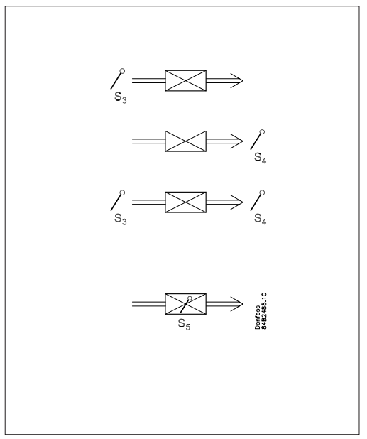
Control de dos compressors
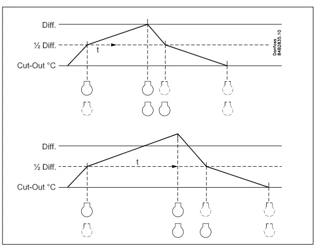
This control is used for controlling two compressors of the same size. The principle for control is that one of the compressors connects at ½ the differential of the thermostat, and the other at the full differential. When the thermostat cuts in the compressor with the fewest operating hours is started. The other compressor will only start after a set time delay, so that the load will be divided between them. The time delay has a higher priority than the temperature.
When the air temperature has dropped by half the differential the one compressor will stop, the other will continue working and not stop until the required temperature is achieved.
The compressors used must be of a type that is capable of starting up against a high pressure.
- Canvi de referència de temperatura
En un aparell d'impulsos, per exempleample, used for various product groups. Here the temperature reference is changed easily with a contact signal on a digital input. The signal raises the normal thermostat value by a predefined amount. At the same time the alarm limits with the same value are displaced accordingly.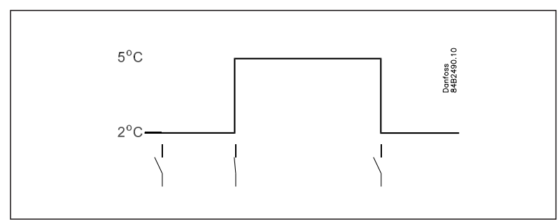
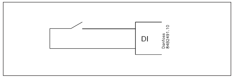
Entrades digitals
There are two digital inputs both of which can be used for the following functions:
- Neteja de caixa
- Funció de contacte de porta amb alarma
- Iniciant una descongelació
- Descongelació coordinada
- Change-over between two temperature reference
- Retransmission of a contact’s position via data communication
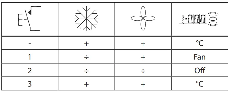
Funció de neteja de la caixa
This function makes it easy to steer the refrigeration appliance through a cleaning phase. Via three pushes on a switch you change from one phase to the next phase.
The first push stops the refrigeration – the fans keep working
- "Més tard": La següent empenta atura els aficionats
- «Encara més tard»: La següent empenta reinicia la refrigeració
The different situations can be followed on the display.
On the network a cleaning alarm is transmitted to the system unit. This alarm can be ”logged” so that proof of the sequence of events is provided.
Porta contacte funció
In cold rooms and frost rooms the door switch can switch the light on and off, start and stop the refrigeration and give alarm if the door has remained open for too long.

Descongelació
Depending on the application you may choose between the following defrost methods:
- Natural: Here the fans are kept operating during the defrost
- Elèctric: L'element calefactor s'activa
- Brine: The valve is kept open so that the brine can flow through the evaporator
- Hotgas: Here the solenoid valves are controlled so that the hotgas can flow through the evaporator
Inici de la descongelació
Un descongelament es pot iniciar de diferents maneres
- Interval: Defrost is started at fixed time intervals, say, every eighth hour
- Temps de refrigeració:
Defrost is started at fixed refrigeration time intervals, in other words, a low need for refrigeration will ”postpone” the coming defrost - Schedule: Here defrost can be started at fixed times of the day and night. However, max. 6 times
- Contact: Defrost is started with a contact signal on a digital input
- Network: The signal for defrost is received from a system unit via the data communication
- S5 temp En sistemes 1:1 es pot seguir l'eficiència de l'evaporador. La formació de gel iniciarà una descongelació.
- Manual: An extra defrost can be activated from the controller’s lower-most button. (Though not for application 4).
Descongelació coordinada
There are two ways in which coordinated defrost can be arranged. Either with wire connections between the controllers or via data communication
Connexions per cable
One of the controllers is defined to be the controlling unit and a battery module may be fitted in it so that the clock is ensured backup. When a defrost is started all the other controllers will follow suit and likewise start a defrost. After the defrost the individual controllers will move into waiting position. When all are in waiting position there will be a change-over to refrigeration.
(Si només un del grup demana descongelació, els altres faran el mateix).
Descongelació mitjançant comunicació de dades
All controllers are fitted with a data communication module, and via the override function from a gateway the defrost can be coordinated.
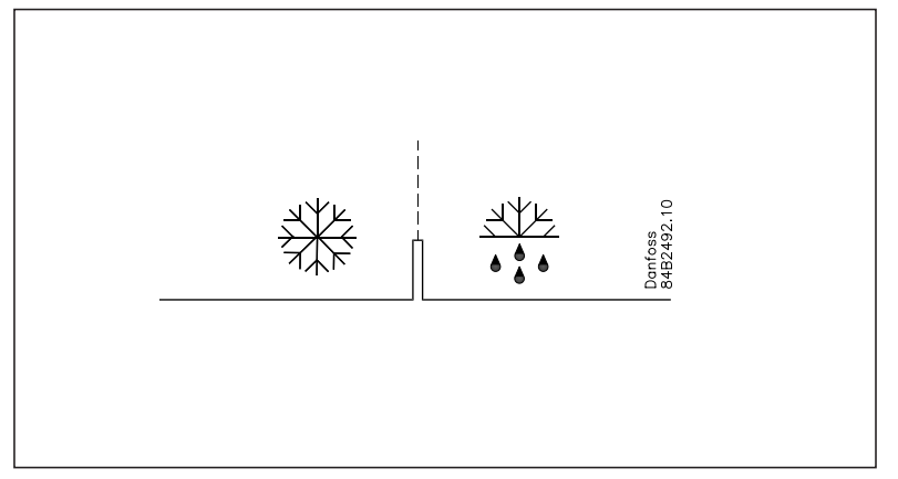
Descongelació sota demanda
- Segons el temps de refrigeració
When the aggregate refrigeration time has passed a fixed time, a defrost will be started. 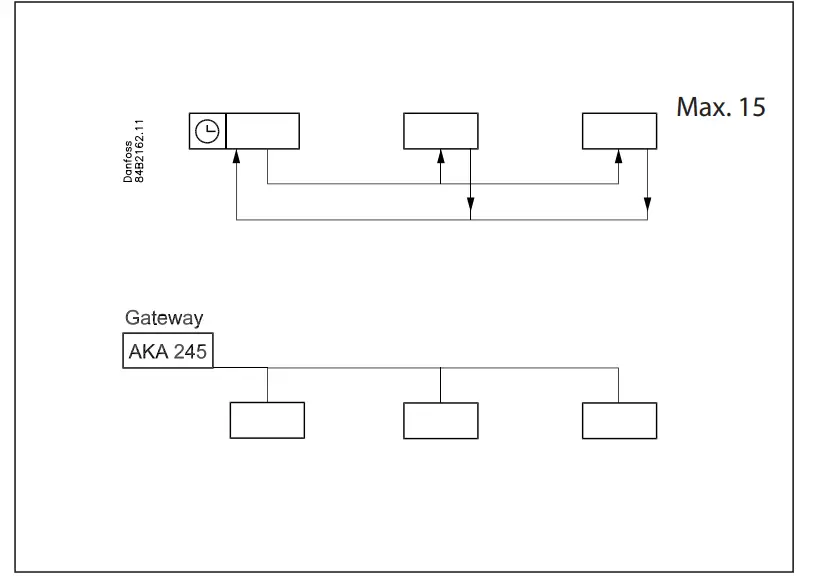 Basat en la temperatura
The controller will constantly follow the temperature at S5. Between two defrosts the S5 temperature will become lower the more the evaporator ices up (the compressor operates for a longer time and pulls the S5 temperature further down). When the temperature passes a set allowed variation the defrost will be started.
This function can only work in 1:1 systems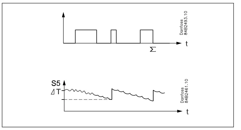
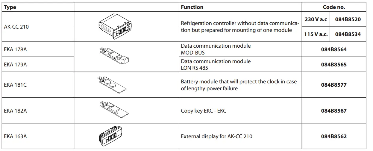
Mòdul extra
- The controller can afterwards be fitted with an insertion module if the application requires it.
The controller has been prepared with plug, so the module simply has to be pushed in- Mòdul de bateria
El mòdul garanteix voltage al controlador si el volum de subministramenttage should drop out for more than four hours. The clock function can thus be protected during a power failure. - Comunicació de dades
Si necessiteu operar des d'un PC, cal instal·lar un mòdul de comunicació de dades al controlador.
- Mòdul de bateria
- Pantalla externa
If it is necessary to indicate the temperature on the front of refrigeration appliance, a display type EKA 163A can be mounted. The extra display will show the same information as the control-ler’s display, but does not incorporate buttons for operation. If operation from the external display is needed a display type EKA 164A must be mounted.

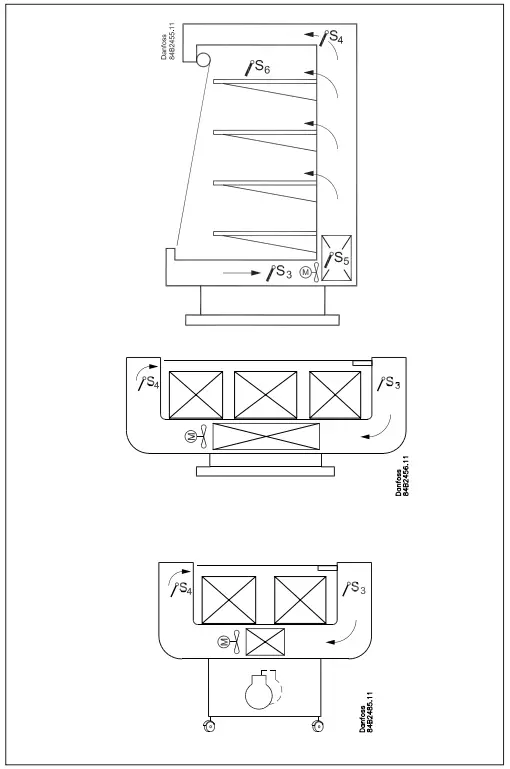
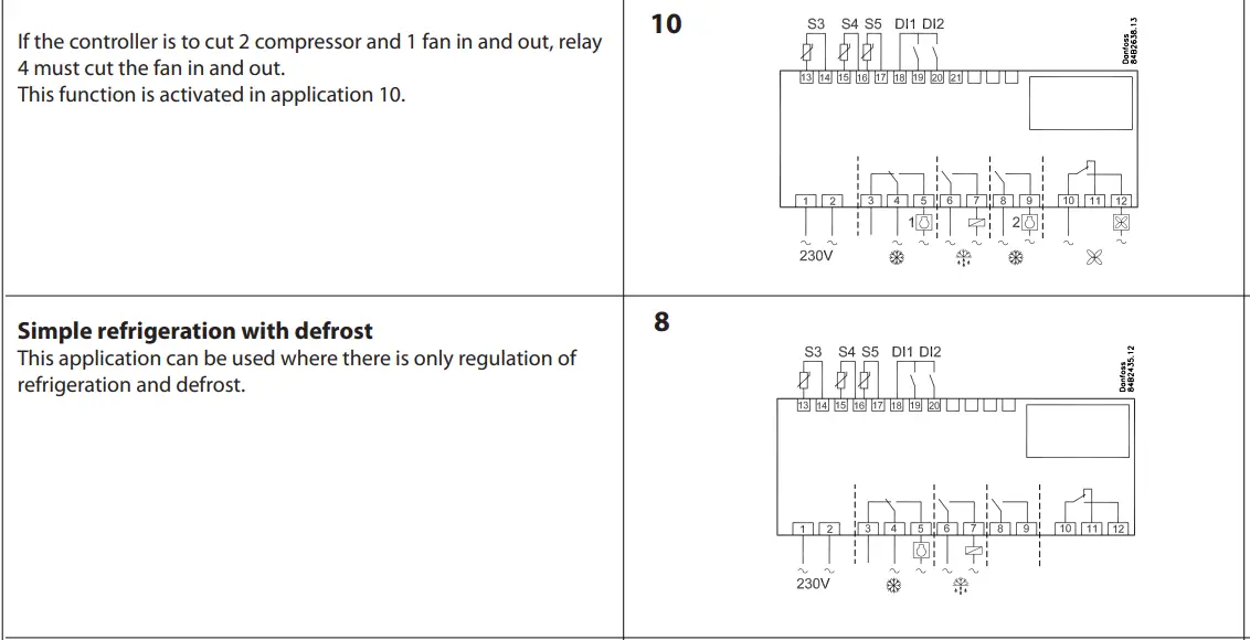
Aplicacions
Here is a survey of the controller’s field of application.
- A setting will define the relay outputs so that the controller’s interface will be targeted to the chosen application.
- On page 20 you can see the relevant settings for the respective wiring diagrams.
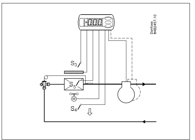
- S3 and S4 are temperature sensors. The application will deter-mine whether either one or the other or both sensors are to be used. S3 is placed in the air flow before the evaporator. S4 after the evaporator.
- Un per centtage setting will determine according to what the control is to be based. S5 is a defrost sensor and is placed on the evaporator.
- DI1 and DI2 are contact functions that can be used for one of the following functions: door function, alarm function, defrost start, external main switch, night operation, change of thermostat reference, appliance cleaning, forced refrigeration or coordinated defrost. See the functions in settings o02 and o37.
Refrigeration control with one compressor
The functions are adapted to small refrigeration systems which either may be refrigeration appliances or cold rooms.
The three relays can control the refrigeration, the defrost and the fans, and the fourth relay can be used for either alarm function, light control or rail heat control
- The alarm function can be linked up with a contact function from a door switch. If the door remains open longer than al-lowed there will be an alarm.
- The light control can also be linked up with a contact function from a door switch. An open door will switch on the light and it will remain lit for two minutes after the door has been closed again.
- The rail heat function can be used in refrigeration or freezing appliances or on the door’s heating element for frost rooms.
The fans can be stopped during defrost and they may also follow a door switch’s open/close situation.
There are several other functions for the alarm function as well as the light control, rail heat control and fans. Please refer to the respective settings.
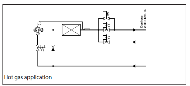
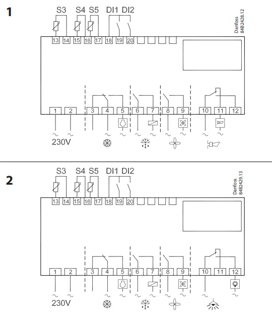 Descongelació de gas calent
This type of connection can be used on systems with hotgas defrost, but only in small systems in, say, supermarkets – the functional content has not been adapted to systems with large charges. Relay 1’s change-over function can be used by the bypass valve and/or the hotgas valve.
Relay 2 is used for refrigeration.


Enquesta de funcions
| Funció | Paràmetre | Parameter by operation via data communication |
| Visualització normal | ||
| Normally the temperature value from one of the two thermostat sensors S3 or S4 or a mixture of the two measurements is displayed.
In o17 the ratio is determined. |
Pantalla d'aire (u56) | |
| Termòstat | Control del termòstat | |
| Punt de consigna
La regulació es basa en el valor configurat més un desplaçament, si escau. El valor s'estableix prement el botó central. The set value can be locked or limited to a range with the settings in r02 and r 03. The reference at any time can be seen in ”u28 Temp. ref” |
Tall °C | |
| Diferencial
When the temperature is higher than the reference + the set differential, the com- pressor relay will be cut in. It will cut out again when the temperature comes down to the set reference. |
r01 | Diferencial |
| Limitació del punt de consigna
The controller’s setting range for the setpoint may be narrowed down, so that much too high or much too low values are not set accidentally – with resulting damages. |
||
| To avoid a too high setting of the setpoint, the max. allowable reference value must be lowered. | r02 | Desconnexió màxima °C |
| To avoid a too low setting of the setpoint, the min. allowable reference value must be increased. | r03 | Desconnexió mínima °C |
| Correcció de la temperatura que es mostra a la pantalla
Si la temperatura dels productes i la temperatura rebuda pel controlador no són idèntiques, es pot dur a terme un ajust de desplaçament de la temperatura que es mostra a la pantalla. |
r04 | Disp. Adj. K |
| Unitat de temperatura
Configureu aquí si el controlador ha de mostrar els valors de temperatura en °C o en °F. |
r05 | Temp. unitat
°C=0. / °F=1 (Only °C on AKM, whatever the set- ting) |
| Correcció del senyal de S4
Possibilitat de compensació mitjançant un cable de sensor llarg |
r09 | Ajustar S4 |
| Correcció del senyal de S3
Possibilitat de compensació mitjançant un cable de sensor llarg |
r10 | Ajustar S3 |
| Inici/parada de la refrigeració
Amb aquesta configuració es pot iniciar, aturar la refrigeració o permetre una anul·lació manual de les sortides. Start / stop of refrigeration can also be accomplished with the external switch func- tion connected to a DI input. Si la refrigeració s'atura, emetrà una "alarma de repòs". |
r12 | Interruptor principal
1: Comença 0: Atura -1: Control manual de sortides permès |
| Valor de retrocés nocturn
La referència del termòstat serà el punt de consigna més aquest valor quan el controlador canviï al funcionament nocturn. (Seleccioneu un valor negatiu si hi ha acumulació de fred.) |
r13 | Desplaçament nocturn |
| Selection of thermostat sensor
Here you define the sensor the thermostat is to use for its control function. S3, S4, or a combination of them. With the setting 0%, only S3 is used (Sin). With 100%, only S4. (For application 9 an S3 sensor must be used) |
r15 | Ther. S4 % |
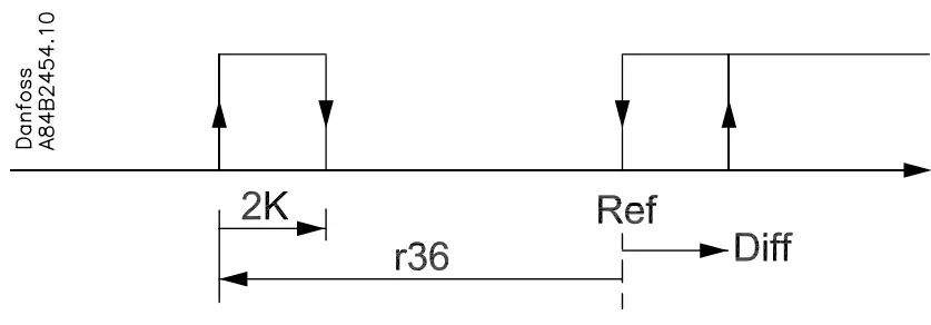
| Funció de calefacció
The function uses the defrost function’s heating element for raising the temperature. The function enters into force a number of degrees (r36) below the actual reference and cuts out again with a differential of 2 degrees. Regulation is carried out with 100% signal from the S3 sensor. The fans will be operating when there is heating. The fans and the heating function will stop if door function has been selected and the door is opened. Where this function is used an external safety cutout should also be installed, so that superheating of the heating element cannot take place. Remember to set D01 to electrical defrosting. |
r36 | HeatStartRel |
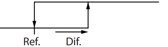
| Activació del desplaçament de referència
When the function is changed to ON the thermostat reference will be displaced by the value in r40. Activation can also take place via input DI1 or DI2 (defined in o02 or o37). |
r39 | Desplaçament tèrmic |
| Valor del desplaçament de referència
The thermostat reference and the alarm values are shifted the following number of degrees when the displacement is activated. Activation can take place via r39 or input DI |
r40 | Desplaçament tèrmic K |
| Night setbck (start of night signal) | ||
| Forced cool.
(start of forced cooling) |
||
| Alarma | Configuració d'alarma | |
| El controlador pot donar alarma en diferents situacions. Quan hi hagi una alarma, tots els díodes emissors de llum (LED) parpellejaran al panell frontal del controlador i el relé d'alarma s'activarà. | Amb la comunicació de dades es pot definir la importància de les alarmes individuals. La configuració es realitza al menú "Destinacions d'alarma". | |
| Retard de l'alarma (retard curt d'alarma)
Si se supera un dels dos valors límit, s'iniciarà una funció de temporitzador. L'alarma no s'activarà fins que s'hagi passat el temps de retard establert. El retard s'estableix en minuts. |
A03 | Retard de l'alarma |
| Time delay for door alarm
El retard de temps s'estableix en minuts. The function is defined in o02 or in o37. |
A04 | Porta oberta del |
| Retard de temps per a la refrigeració (retard d'alarma llarg)
This time delay is used during start-up, during defrost, immediately after a defrost. There will be change-over to the normal time delay (A03) when the temperature has dropped below the set upper alarm limit. El retard de temps s'estableix en minuts. |
A12 | Eliminació desplegable |
| Límit superior d'alarma
Here you set when the alarm for high temperature is to start. The limit value is set in °C (absolute value). The limit value will be raised during night operation. The value is the same as the one set for night setback, but will only be raised if the value is positive. El valor límit també s'elevarà en relació amb el desplaçament de referència r39. |
A13 | Aire de baixa intensitat |
| Límit d'alarma inferior
Aquí definiu quan s'ha d'iniciar l'alarma per a baixa temperatura. El valor límit s'estableix en °C (valor absolut). El valor límit també s'elevarà en relació amb el desplaçament de referència r39. |
A14 | Aire de baixa intensitat |
| Retard d'una alarma DI1
Una entrada de tall/de tall donarà lloc a una alarma quan s'hagi passat el retard. La funció es defineix a o02. |
A27 | AI.Retard DI1 |
| Retard d'una alarma DI2
A cut-out/cut-in input will result in alarm when the time delay has been passed. The function is defined in o37 |
A28 | AI.Retard DI2 |
| Senyal al termòstat d'alarma
Here you have to define the ratio between the sensors which the alarm thermostat has to use. S3, S4 or a combination of the two. With setting 0% only S3 is used. With 100% only S4 is used |
A36 | Alarm S4% |
| Restableix l'alarma | ||
| Error EKC |

| Compressor | Control del compressor | |
| The compressor relay works in conjunction with the thermostat. When the thermo- stat calls for refrigeration will the compressor relay be operated. | ||
| Temps de funcionament
Per evitar un funcionament irregular, es poden establir valors per al temps que ha de funcionar el compressor un cop s'ha posat en marxa. I durant quant de temps almenys s'ha d'aturar. Els temps de funcionament no es respecten quan comencen els descongelaments. |
||
| Temps mínim d'activació (en minuts) | c01 | Min. A temps |
| Temps mínim d'aturada (en minuts) | c02 | Min. Temps lliure |
| Time delay for couplings of two compressors
Els paràmetres indiquen el temps que ha de transcórrer des que s'activa el primer relé i fins que s'ha d'activar el següent relé. |
c05 | Retard de pas |
| Reversed relay function for D01
0: Funció normal on el relé s'activa quan es demana refrigeració 1: Reversed function where the relay cuts out when refrigeration is demanded (this wiring produces the result that there will be refrigeration if the supply voltage al controlador falla). |
c30 | Relé CMP NC |
| El LED de la part frontal del controlador mostrarà si la refrigeració està en curs. | Comp Relay
Here you can read the status of the compressor relay, or you can force- control the relay in the ”Manual control” mode |
|
| Descongelació | Control de descongelació | |
|
||
Mètode de descongelació
|
d01 | Mètode predeterminat 0 = no
1 = El 2 = Gas 3= Brine |
| Temperatura de parada de descongelació
El descongelament s'atura a una temperatura determinada que es mesura amb un sensor (el sensor es defineix a d10). El valor de la temperatura està establert. |
d02 | Temperatura d'aturada predeterminada |
Interval entre inicis de descongelació
|
d03 | Interval predefinit (0=desactivat) |
| Màx. durada de descongelació
Aquesta configuració és un temps de seguretat, de manera que el descongelament s'aturarà si no hi ha hagut ja una aturada basada en la temperatura o mitjançant un descongelament coordinat. |
d04 | Temps màxim de definició |
Temps staggering for defrost cut ins during start-up
|
d05 | Temps Stagg. |
| Temps de degoteig
Aquí definiu el temps que ha de transcórrer des d'un descongelament fins que el compressor ha de tornar a engegar-se. (El temps en què l'aigua goteja de l'evaporador). |
d06 | Temps de degoteig |
| Retard de l'arrencada del ventilador després del descongelament
Aquí definiu el temps que ha de transcórrer des de l'inici del compressor després d'un descongelament i fins que el ventilador pugui tornar a engegar-se. (El temps en què l'aigua està "lligada" a l'evaporador). |
d07 | FanStartDel |
| Temperatura d'inici del ventilador
El ventilador també es pot engegar una mica abans del que s'esmenta a "Retard de l'arrencada del ventilador després del descongelament", si el sensor de descongelació S5 registra un valor inferior al que s'ha establert aquí. |
d08 | Temp. d'inici del ventilador |
| El ventilador s'ha engegat durant la descongelació
Here you can set whether fan is to operate during defrost. 0: Stopped (Runs during pump down)
|
d09 | FanDuringDef |
| Sensor de descongelació
Here you define the defrost sensor. 0: None, defrost is based on time 1: S5 2: S4 |
d10 | DefStopSens. |
| Pumpdown delay
Set the time where the evaporator is emptied of refrigerant prior to the defrost. |
d16 | Pump dwn del. |
| Drain delay (only in connection with hotgas)
Set the time where the evaporator is emptied of condensed refrigerant after the defrost. |
d17 | Drain del |
| Descongelació a demanda: temps total de refrigeració
Aquí s'estableix el temps de refrigeració permès sense descongelacions. Si passa el temps, s'iniciarà una descongelació. Amb l'ajust = 0, la funció es talla. |
d18 | MaxTherRunT |
| Descongelació a demanda – temperatura S5
The controller will follow the effectivity of the evaporator, and via internal calcula- tions and measurements of the S5 temperature it will be able to start a defrost when the variation of the S5 temperature becomes larger than required. Aquí definiu la mida que es pot permetre un desplaçament de la temperatura S5. Quan es passa el valor, s'iniciarà un descongelament. La funció només es pot utilitzar en sistemes 1:1 quan la temperatura d'evaporació baixarà per garantir que la temperatura de l'aire es mantingui. En sistemes centralitzats, la funció s'ha de desactivar. Amb el paràmetre = 20, la funció es desactiva. |
d19 | RetallS5Dif. |
| Delay of the hot gas injection
Can be used when vales of the type PMLX and GPLX are used. Time is set so that the valve is closed completely before the hot gas is turned on. |
d23 | — |
| Si voleu veure la temperatura al sensor de descongelació, premeu el botó inferior del controlador. | Temperatura de descongelació. | |
| Si voleu iniciar una descongelació addicional, premeu el botó inferior del controlador durant quatre segons.
You can stop an ongoing defrost in the same way |
Inici predeterminat
Aquí podeu iniciar una descongelació manual |
|
| El LED de la part frontal del controlador indicarà si s'està duent a terme una descongelació. | Relé de descongelació
Aquí podeu llegir l'estat del relé de descongelació o podeu forçar el control del relé en mode "Control manual". |
|
| Mantenir premut després de la defensa
Mostra ON quan el controlador funciona amb descongelació coordinada. |
||
| Estat de descongelació Estat en descongelació
1= bombament / descongelació |
||
| Ventilador | Control del ventilador | |
| Fan stopped at cut-out compressor
Aquí podeu seleccionar si el ventilador s'ha d'aturar quan el compressor s'apagui |
F01 | Parada del ventilador CO
(Sí = Ventilador aturat) |
| Delay of fan stop when compressor is cut out
Si heu triat aturar el ventilador quan el compressor està apagat, podeu endarrerir l'aturada del ventilador quan el compressor s'hagi aturat. Aquí podeu configurar el retard de temps. |
F02 | Fan del. CO |
| Temperatura de parada del ventilador
The function stops the fans in an error situation, so that they will not provide power to the appliance. If the defrost sensor registers a higher temperature than the one set here, the fans will be stopped. There will be re-start at 2 K below the setting. The function is not active during a defrost or start-up after a defrost. With setting +50°C the function is interrupted. |
F04 | Temperatura d'aturada del ventilador. |
| El LED de la part frontal del controlador indicarà si el ventilador està funcionant. | Relé de ventilador
Aquí podeu llegir l'estat del relé del ventilador o forçar el control del relé en mode "Control manual". |
| APPCC | APPCC | |
| HACCP temperature
Here you can see the temperature measurement that transmits signal to the function |
h01 | HACCP temp. |
| Last too high HACCP temperature was registered in connection with: (Value can be read out).
H01: Temperature exceeding during normal regulation. H02: Temperature exceeding during power failure. Battery backup controls the times. H03: Temperature exceeding during power failure. No control of times. |
h02 | – |
| Last time the HACCP temperature was exceeded: Year | h03 | – |
| Last time the HACCP temperature was exceeded: Month | h04 | – |
| Last time the HACCP temperature was exceeded: Day | h05 | – |
| Last time the HACCP temperature was exceeded: Hour | h06 | – |
| Last time the HACCP temperature was exceeded: Minute | h07 | – |
| Last exceeding: Duration in hours | h08 | – |
| Last exceeding: Duration in minutes | h09 | – |
| Temperatura màxima
The highest measured temperature will continuously be saved when the temperature exceeds the limit value in h12. The value can be read out until the next time the tem- perature exceeds the limit value. After that it is overwritten with the new measure- ments. |
h10 | Temp.max. |
| Selection of function 0: No HACCP function
1: S3 and/or S4 used as sensor. Definition takes place in h14. 2: S5 used as sensor. |
h11 | HACCP sensor |
| Límit d'alarma
Here you set the temperature value at which the HACCP function is to enter into force. When the value becomes higher than the set one, the time delay starts. |
h12 | HACCP limit |
| Time delay for the alarm (only during normal regulation). When the time delay has been passed the alarm is activated. | h13 | HACCP delay |
| Selection of sensors for the measuring
If the S4 sensor and/or the S3 sensor is used, the ratio between them must be set. At setting 100% only S4 is used. At setting 0% only S3 is used. |
h14 | HACCP S4% |
| Funció de programació/rellotge de descongelació interna | ||
| (No s'utilitza si s'utilitza un programa de descongelació extern mitjançant comunicació de dades.) Es poden configurar fins a sis hores individuals per a l'inici de la descongelació al llarg del dia. | ||
| Inici de descongelació, configuració de l'hora | t01-t06 | |
| Defrost start, minute setting (1 and 11 belong together, etc.) When all t01 to t16 equal 0 the clock will not start defrosts. | t11-t16 | |
| Rellotge en temps real
Només cal ajustar el rellotge quan no hi ha comunicació de dades. En cas d'una fallada de corrent de menys de quatre hores, la funció de rellotge es conservarà. Quan es munta un mòdul de bateria, la funció de rellotge es pot conservar durant més temps. També hi ha una indicació de data que s'utilitza per al registre de les mesures de temperatura. |
||
| Rellotge: Configuració de l'hora | t07 | |
| Rellotge: ajust dels minuts | t08 | |
| Rellotge: Configuració de la data | t45 | |
| Rellotge: Configuració del mes | t46 | |
| Rellotge: Configuració de l'any | t47 | |
| Diversos | Diversos | |
| Delay of output signal after start-up
Start-up after a power failure the controller’s functions can be delayed so that over- loading of the electricity supply network is avoided. Aquí podeu configurar el retard de temps. |
o01 | RetardDeSortida. |
| Senyal d'entrada digital – DI1
The controller has a digital input 1 which can be used for one of the following func- tions: Desactivat: L'entrada no s'utilitza
|
o02 | Configuració de l'entrada DI 1
Definition takes place with the nu- merical value shown to the left.
(0 = apagat)
Estat DI (Mesura) L'estat actual de l'entrada DI es mostra aquí. ON o OFF. |
|
After installation of a data communi- cation module the controller can be operated on an equal footing with the other controllers in ADAP-KOOL® refrigeration controls. | |
| o03 | ||
| o04 | ||
| Codi d'accés 1 (Accés a tots els paràmetres)
If the settings in the controller are to be protected with an access code you can set a numerical value between 0 and 100. If not, you can cancel the function with setting 0. (99 will always give you access). |
o05 | – |
| Tipus de sensor
Normally a Pt 1000 sensor with great signal accuracy is used. But you can also use a sensor with another signal accuracy. That may either be a PTC 1000 sensor (1000 ohm) or an NTC sensor (5000 Ohm at 25°C). Tots els sensors muntats han de ser del mateix tipus. |
o06 | SensorConfig Pt = 0
PTC = 1 NTC = 2 |
| Pas de visualització
Sí: Dóna passos de 0.5° No: Dóna passos de 0.1° |
o15 | Pas de disp. = 0.5 |
| Temps màxim d'espera després de descongelacions coordinadest
Quan un controlador ha completat una descongelació, esperarà un senyal que indiqui que es pot reprendre la refrigeració. Si aquest senyal no apareix per una raó o una altra, el controlador iniciarà la refrigeració quan hagi transcorregut aquest temps d'espera. |
o16 | Temps de retenció màxim |
| Select signal for the display S4%
Here you define the signal to be shown by the display. S3, S4, or a combination of the two. With setting 0% only S3 is used. With 100% only S4. |
o17 | Disp. S4% |
| Digital input signal – D2
The controller has a digital input 2 which can be used for one of the following func- tions: Desactivat: L'entrada no s'utilitza.
|
o37 | Configuració DI2. |
Configuració de la funció de llum (relé 4 a les aplicacions 2 i 6)
|
o38 | Configuració de llum |
| Activation of light relay
El relé de llum es pot activar aquí, però només si es defineix a o38 amb la configuració 2. |
o39 | Comandament a distància de llum |
| Calor del ferrocarril durant el funcionament diürn
El període ON s'estableix com a percentatgetage of the time |
o41 | Railh.ON dia% |
| Calor del ferrocarril durant el funcionament nocturn
El període ON s'estableix com a percentatgetage of the time |
o42 | Railh.ON ngt% |
| Cicle de calor del ferrocarril
The period of time for the aggregate ON time + OFF time is set in minutes |
o43 | Cicle ferroviari |
Neteja de caixa
If the function is controlled by a signal at the DI1 or DI2 input, the relevant status can be seen here in the menu. |
o46 | Neteja de la caixa |
| Selecció d'aplicació
The controller can be defined in various ways. Here you set which of the 10 applica- tions is required. On page 6 you can see a survey of applications. This menu can only be set when regulation is stopped, i.e. “r12” is set to 0. |
o61 | — Appl. Mode (only output in Danfoss only) |
| Transfer a set of presetting to the controller
És possible seleccionar una configuració ràpida de diversos paràmetres. Depèn de si s'ha de controlar una aplicació o una habitació i si el descongelament s'ha d'aturar en funció del temps o de la temperatura. L'enquesta es pot veure a la pàgina 22. This menu can only be set when regulation is stopped, i.e. “r12” is set to 0.
After the setting the value will return to 0. Any subsequent adjustment/setting of parameters can be made, as required. |
o62 | – |
| Codi d'accés 2 (Accés als ajustaments)
There is access to adjustments of values, but not to configuration settings. If the set- tings in the controller are to be protected with an access code you can set a numeri- cal value between 0 and 100. If not, you can cancel the function with setting 0. If the function is used, access code 1 (o05) també ha de ser utilitzat. |
o64 | – |
| Copia la configuració actual del controlador
With this function the controller’s settings can be transferred to a programming key. The key can contain up to 25 different sets. Select a number. All settings except for Application (o61) and Address (o03) will be copied. When copying has started the dis- play returns to o65. After two seconds you can move into the menu again and check whether the copying was satisfactory. Showing of a negative figure spells problems. See the significance in the Fault Mes- sage section. |
o65 | – |
| Copiar de la clau de programació
This function downloads a set of settings earlier saved in the controller. Select the relevant number. All settings except for Application (o61) and Address (o03) will be copied. When copy- ing has started the display returns to o66. After two seconds you can move back into the menu again and check whether the copying was satisfactory. Showing of a nega- tive figure spells problems. See the significance in the Fault Message section. |
o66 | – |
| Desa com a configuració de fàbrica
Amb aquesta configuració deseu la configuració real del controlador com una nova configuració bàsica (la configuració de fàbrica anterior es sobreescriu). |
o67 | – |
| – – – Reducció nocturna 0 = Dia
1=Nit |
| Servei | Servei | |
| Temperatura mesurada amb sensor S5 | u09 | S5 temp. |
| Estat a l'entrada DI1. activat/1=tancat | u10 | Estat DI1 |
| Temperatura mesurada amb sensor S3 | u12 | Temperatura de l'aire S3 |
| Estat en funcionament nocturn (activat o desactivat) 1=tancat | u13 | Condicionament nocturn. |
| Temperatura mesurada amb sensor S4 | u16 | Temperatura de l'aire S4 |
| Temperatura del termòstat | u17 | Allà. aire |
| Llegeix la referència del present reglament | u28 | Ref. de temperatura |
| Estat a la sortida DI2. activat/1=tancat | u37 | Estat DI2 |
| Temperatura que es mostra a la pantalla | u56 | Mostra l'aire |
| Temperatura mesurada per al termòstat d'alarma | u57 | Alarm air |
| ** Status on relay for cooling | u58 | Comp1/LLSV |
| ** Status on relay for fan | u59 | Relleu de ventilador |
| ** Estat del relé per a la descongelació | u60 | Relé definitiu |
| ** Status on relay for railheat | u61 | Relé ferroviari |
| ** Status on relay for alarm | u62 | Relé d'alarma |
| ** Status on relay for light | u63 | Relleu de llum |
| ** Status on relay for valve in suction line | u64 | SuctionValve |
| ** Estat del relé per al compressor 2 | u67 | Relé Comp2 |
| *) Not all items will be shown. Only the function belonging to the selected applica- tion can be seen. |
| Missatge d'error | Alarmes | |
| In an error situation the LED’s on the front will flash and the alarm relay will be acti- vated. If you push the top button in this situation you can see the alarm report in the display. If there are more keep on pushing to see them.
Hi ha dos tipus d'informes d'error: pot ser una alarma que es produeix durant el funcionament diari o pot haver-hi un defecte a la instal·lació. Les alarmes A no seran visibles fins que no hagi transcorregut el retard configurat. Les alarmes electròniques, en canvi, es faran visibles en el moment que es produeixi l'error. (Una alarma A no serà visible mentre hi hagi una alarma E activa). Aquests són els missatges que poden aparèixer: |
1 = alarma |
|
| A1: Alarma d'alta temperatura | Alarma de temperatura alta | |
| A2: Alarma de baixa temperatura | Alarma de baixa temperatura | |
| A4: Alarma de porta | Alarma de la porta | |
| A5: Informació. El paràmetre o16 ha caducat. | Temps de retenció màxim | |
| A15: Alarma. Senyal de l'entrada DI1 | Alarma DI1 | |
| A16: Alarma. Senyal de l'entrada DI2 | Alarma DI2 | |
| A45: Standby position (stopped refrigeration via r12 or DI input) (Alarm relay will not be activated) | Mode d'espera | |
| A59: Neteja de la carcassa. Senyal de l'entrada DI1 o DI2 | Neteja de caixa | |
| A60: High-temperature alarm for the HACCP function | Alarma APPCC | |
| Temps màxim de definició | ||
| E1: Errors al controlador | Error EKC | |
| E6: Error en el rellotge en temps real. Comproveu la bateria / reinicieu el rellotge. | – | |
| E25: Error de sensor a S3 | Error S3 | |
| E26: Error de sensor a S4 | Error S4 | |
| E27: Error de sensor a S5 | Error S5 | |
When copying settings to or from a copying key with functions o65 or o66, the fol- lowing information may appear:
(The information can be found in o65 or o66 a couple of seconds after copying has been started). |
||
| Destinacions d'alarma | ||
| La importància de les alarmes individuals es pot definir amb un paràmetre (0, 1, 2 o 3) |
| Estat de funcionament | (mesura) | |
| El controlador passa per algunes situacions de regulació on només espera el següent punt de la regulació. Per fer que aquestes situacions de "per què no passa res"
visible, you can see an operating status on the display. Push briefly (1s) the upper but- ton. If there is a status code, it will be shown on the display. Els codis d'estat individuals tenen els significats següents: |
Estat de l'EKC:
(Es mostra a totes les pantalles de menú) |
|
| S0: Regulació | 0 | |
| S1: Waiting for end of the coordinated defrost | 1 | |
| S2: When the compressor is operating it must run for at least x minutes. | 2 | |
| S3: Quan el compressor està aturat, ha de romandre aturat durant almenys x minuts. | 3 | |
| S4: L'evaporador degota i espera que s'acabi el temps | 4 | |
| S10: Refrigeration stopped by main switch. Either with r12 or a DI-input | 10 | |
| S11: Refrigeració aturada pel termostat | 11 | |
| S14: Defrost sequence. Defrost in progress | 14 | |
| S15: Seqüència de descongelació. Retard del ventilador: l'aigua s'uneix a l'evaporador. | 15 | |
| S17: Door is open. DI input is open | 17 | |
| S20: Refrigeració d'emergència *) | 20 | |
| S25: Control manual de sortides | 25 | |
| S29: Neteja de la caixa | 29 | |
| S30: Forced cooling | 30 | |
| S32: Retard a les sortides durant l'arrencada | 32 | |
| S33: Heat function r36 is active | 33 | |
| Altres visualitzacions: | ||
| non: The defrost temperature cannot be displayed. There is stop based on time | ||
| -d-: Descongelació en curs / Primer refredament després de la descongelació | ||
| PD: Cal una contrasenya. Estableix la contrasenya |
*) Emergency cooling will take effect when there is lack of signal from a defined S3 or S4 sensor. The regulation will continue with a registered average cutin frequency. There are two registered values – one for day operation and one for night operation.
Warning ! Direct start of compressors *
To prevent compressor breakdown parameter c01 and c02 should be set according to suppliers requirements or in general : Hermetic Compressors c02 min. 5 minutes
Semihermetic Compressors c02 min. 8 minutes and c01 min. 2 to 5 minutes ( Motor from 5 to 15 KW )
* ) Direct activating of solenoid valves does not require settings different from factory (0)
Funcionament
Mostra
Els valors es mostraran amb tres dígits, i amb una configuració podeu determinar si la temperatura s'ha de mostrar en °C o en °F.
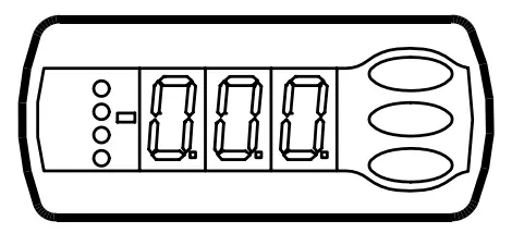
Díodes emissors de llum (LED) al panell frontal
HACCP = HACCP function is active
The other LED’s on the front panel will light up when the belong-ing relay is activated.

Els díodes emissors de llum parpellejaran quan hi hagi una alarma.
En aquesta situació, podeu descarregar el codi d'error a la pantalla i cancel·lar/signar l'alarma prement breument el botó superior.
Descongelació
Durant el descongelament es mostra una –d- a la pantalla. Això view will con-tinue up till 15 min. after the cooling has resumed.
Tanmateix el view de –d- s'interromprà si:
- La temperatura és adequada dins dels 15 minuts
- La regulació s'atura amb "Interruptor principal"
- Apareix una alarma de temperatura alta
Els botons
When you want to change a setting, the upper and the lower buttons will give you a higher or lower value depending on the button you are pushing. But before you change the value, you must have access to the menu. You obtain this by pushing the upper button for a couple of seconds – you will then enter the col-umn with parameter codes. Find the parameter code you want to change and push the middle buttons until value for the parameter is shown. When you have changed the value, save the new value by once more pushing the middle button.
Examples
Set menú
- Premeu el botó superior fins que es mostri un paràmetre r01
- Premeu el botó superior o inferior i trobeu el paràmetre que voleu canviar
- Premeu el botó central fins que es mostri el valor del paràmetre
- Premeu el botó superior o inferior i seleccioneu el valor nou
- Torneu a prémer el botó central per congelar el valor.
Tallar el relé d'alarma / alarma de rebut / veure el codi d'alarma
- Push short the upper button
Si hi ha diversos codis d'alarma, es troben en una pila rodant. Premeu el botó superior o inferior per escanejar la pila rodant.
Ajustar la temperatura
- Premeu el botó central fins que es mostri el valor de temperatura
- Premeu el botó superior o inferior i seleccioneu el valor nou
- Torneu a prémer el botó central per concloure la configuració.
Lectura de la temperatura al sensor de descongelació
Premeu curt el botó inferior
Inici o aturada manual d'un descongelament
Push the lower button for four seconds.(Though not for application 4).
See HACCP registration
- Give the middle button a long push until h01 appears
- Select required h01-h10
- See value by giving the middle button a short push
Comenceu bé
With the following procedure you can start regulation very quick-ly:
- Obriu el paràmetre r12 i atureu la regulació (en una unitat nova i no configurada anteriorment, r12 ja estarà posat a 0, el que significa regulació aturada).
- Select electric connection based on the drawings on page 6
- Obriu el paràmetre o61 i configureu-hi el número de connexió elèctrica.
- Now select one of the preset settings from the table on page 22.
- Open parameter o62 and set the number for the array of preset- tings. The few selected settings will now be transferred to the menu.
- Obriu el paràmetre r12 i inicieu la regulació
- Reviseu l'enquesta de la configuració de fàbrica. Els valors de les cel·les grises es modifiquen segons la configuració que trieu. Feu els canvis necessaris als paràmetres respectius.
- For network. Set the address in o03 and then transmit it to the gateway/system unit with setting o04.
APPCC
This function will follow the appliance temperature and sound an alarm if the set temperature limit is exceeded. The alarm will come when the time delay has elapsed.
When the temperature exceeds the limit value it will continuously be registered and the peak value will be saved until the later rea-dout. Saved together with the value will be the time and duration of the temperature exceeding.
Examples of temperature exceeding:
Exceeding during normal regulation

Exceeding in connection with power failure where the controller can keep on registering the time performance.

Exceeding in connection with power failure when the controller has lost its clock function and hence also its time performance.
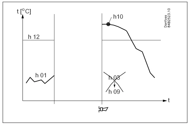
The readout of the various values in the HACCP function can take place with a long push on the middle button.
The readouts are, as follows:
- h01: The temperature
- h02: Readout of the controller’s status when temperature was exceeded:
- H1 = normal regulation.
- H2 = power failure. Times are saved.
- H3 = power failure. Times not saved.
- h03: Time. Year
- h04: Time. Month
- h05: Time: Day
- h06: Time. Hour
- h07: Time. Minute
- h08: Duration in hours
- h09: Duration in minutes
- h10: The registered peak temperature
(Setup of the function takes place just like the other setups. See menu survey on the next page).
| Paràmetres | Número del diagrama EL (pàgina 6) | Mín.-
valor |
Màx.-
valor |
Fàbrica
configuració |
Real
configuració |
|||||||||||
| Funció | Codis | 1 | 2 | 3 | 4 | 5 | 6 | 7 | 8 | 9 | 10 | |||||
| Funcionament normal | ||||||||||||||||
| Temperatura (punt de consigna) | — | -50.0°C | 50.0 °C | 2.0 °C | ||||||||||||
| Termòstat | ||||||||||||||||
| Diferencial | *** | r01 | 0.1 K | 20.0K | 2.0 K | |||||||||||
| Màx. limitació de la configuració del punt de consigna | *** | r02 | -49.0°C | 50 °C | 50.0 °C | |||||||||||
| Min. limitació de la configuració del punt de consigna | *** | r03 | -50.0°C | 49.0 °C | -50.0°C | |||||||||||
| Ajust de la indicació de temperatura | r04 | -20.0 K | 20.0 K | 0.0 K | ||||||||||||
| Unitat de temperatura (°C/°F) | r05 | °C | °F | °C | ||||||||||||
| Correcció del senyal de S4 | r09 | -10.0 K | +10.0 K | 0.0 K | ||||||||||||
| Correcció del senyal de S3 | r10 | -10.0 K | +10.0 K | 0.0 K | ||||||||||||
| Servei manual, regulació d'aturada, regulació d'inici (-1, 0, 1) | r12 | -1 | 1 | 0 | ||||||||||||
| Desplaçament de referència durant el funcionament nocturn | r13 | -10.0 K | 10.0 K | 0.0 K | ||||||||||||
| Definició i ponderació, si escau, dels sensors de termostat
– S4% (100%=S4, 0%=S3) |
r15 | 0% | 100% | 100% | ||||||||||||
| La funció de calefacció s'inicia uns quants graus per sota del
temperatura de tall dels termostats |
r36 | -15.0 K | -3.0 K | -15.0 K | ||||||||||||
| Activació del desplaçament de referència r40 | r39 | OFF | ON | OFF | ||||||||||||
| Valor del desplaçament de referència (activar via r39 o DI) | r40 | -50.0 K | 50.0 K | 0.0 K | ||||||||||||
| Alarma | ||||||||||||||||
| Retard per a l'alarma de temperatura | A03 | 0 min | 240 min | 30 min | ||||||||||||
| Retard de l'alarma de la porta | *** | A04 | 0 min | 240 min | 60 min | |||||||||||
| Retard de l'alarma de temperatura després de la descongelació | A12 | 0 min | 240 min | 90 min | ||||||||||||
| Límit d'alarma alt | *** | A13 | -50.0°C | 50.0 °C | 8.0 °C | |||||||||||
| Límit d'alarma baix | *** | A14 | -50.0°C | 50.0 °C | -30.0°C | |||||||||||
| Retard d'alarma DI1 | A27 | 0 min | 240 min | 30 min | ||||||||||||
| Retard d'alarma DI2 | A28 | 0 min | 240 min | 30 min | ||||||||||||
| Senyal per al termòstat d'alarma. S4% (100%=S4, 0%=S3) | A36 | 0% | 100% | 100% | ||||||||||||
| Compressor | ||||||||||||||||
| Min. Puntual | c01 | 0 min | 30 min | 0 min | ||||||||||||
| Min. temps OFF | c02 | 0 min | 30 min | 0 min | ||||||||||||
| Retard de temps per a l'engegada del component 2 | c05 | 0 seg | 999 seg | 0 seg | ||||||||||||
| El relé 1 del compressor s'ha d'activar i desactivar inversament
(Funció NC) |
c30 | 0
OFF |
1
ON |
0
OFF |
||||||||||||
| Descongelació | ||||||||||||||||
| Mètode de descongelació (cap/EL/GAS/SALMORANA) | d01 | no | bri | EL | ||||||||||||
| Temperatura de parada de descongelació | d02 | 0.0 °C | 25.0 °C | 6.0 °C | ||||||||||||
| Interval entre inicis de descongelació | d03 | 0 hores | 240
hores |
8 hores | ||||||||||||
| Màx. durada de descongelació | d04 | 0 min | 180 min | 45 min | ||||||||||||
| Desplaçament del temps en l'inici de la descongelació a l'arrencada | d05 | 0 min | 240 min | 0 min | ||||||||||||
| Temps de goteig | d06 | 0 min | 60 min | 0 min | ||||||||||||
| Retard per a l'inici del ventilador després del descongelat | d07 | 0 min | 60 min | 0 min | ||||||||||||
| Temperatura d'inici del ventilador | d08 | -15.0°C | 0.0 °C | -5.0°C | ||||||||||||
| Cutin del ventilador durant la descongelació
0: aturat 1: Córrer 2: Funcionant durant el bombament i la descongelació |
d09 | 0 | 2 | 1 | ||||||||||||
| Sensor de descongelació (0=temps, 1=S5, 2=S4) | d10 | 0 | 2 | 0 | ||||||||||||
| Retard de bombeig | d16 | 0 min | 60 min | 0 min | ||||||||||||
| Retard de drenatge | d17 | 0 min | 60 min | 0 min | ||||||||||||
| Temps màxim de refrigeració agregat entre dos descongelacions | d18 | 0 hores | 48 hores | 0 hores | ||||||||||||
| Descongelació a demanda – variació permesa de la temperatura S5 durant-
ing frost build-up. On central plant choose 20 K (=off) |
d19 | 0.0 K | 20.0 k | 20.0 K | ||||||||||||
| Delay of hot gas defrost | d23 | 0 min | 60 min | 0 min | ||||||||||||
| Ventilador | ||||||||||||||||
| Parada del ventilador en el compressor de desconnexió | F01 | no | sí | no | ||||||||||||
| Retard de l'aturada del ventilador | F02 | 0 min | 30 min | 0 min | ||||||||||||
| Temperatura d'aturada del ventilador (S5) | F04 | -50.0°C | 50.0 °C | 50.0 °C | ||||||||||||
| APPCC | ||||||||||||||||
| Mesura de la temperatura real per a la funció HACCP | h01 | |||||||||||||||
| Última temperatura màxima registrada | h10 | |||||||||||||||
| Selecció de funció i sensor per a la funció HACCP. 0 = no
Funció HACCP. 1 = S4 utilitzat (potser també S3). 2 = S5 utilitzat |
h11 | 0 | 2 | 0 | ||||||||||||
| Límit d'alarma per a la funció HACCP | h12 | -50.0°C | 50.0 °C | 8.0 °C | ||||||||||||
| Retard de temps per a l'alarma HACCP | h13 | 0 min. | 240 min. | 30 min. | ||||||||||||
| Seleccioneu el senyal per a la funció HACCP. S4% (100% = S4, 0% = S3) | h14 | 0% | 100% | 100% | ||||||||||||
| Rellotge en temps real | ||||||||||||||||
| Sis horaris d'inici per a la descongelació. Configuració d'hores.
0 = DESACTIVAT |
t01-t06 | 0 hores | 23 hores | 0 hores | ||||||||||||
| Sis horaris d'inici per a la descongelació. Configuració de minuts.
0 = DESACTIVAT |
t11-t16 | 0 min | 59 min | 0 min | ||||||||||||
| Rellotge - Configuració de les hores | *** | t07 | 0 hores | 23 hores | 0 hores | |||||||||||
| Rellotge - Configuració dels minuts | *** | t08 | 0 min | 59 min | 0 min | |||||||||||
| Rellotge - Configuració de la data | *** | t45 | 1 | 31 | 1 | |||||||||||
| Rellotge - Configuració del mes | *** | t46 | 1 | 12 | 1 | |||||||||||
| Rellotge - Configuració de l'any | *** | t47 | 0 | 99 | 0 | |||||||||||
| Diversos | ||||||||||||||||
| Retard dels senyals de sortida després d'una fallada d'alimentació | o01 | 0 s | 600 s | 5 s | ||||||||||||
| 1 | 2 | 3 | 4 | 5 | 6 | 7 | 8 | 9 | 10 | |||||||
| Senyal d'entrada a DI1. Funció:
0=not used. 1=status on DI1. 2=door function with alarm when open. 3=door alarm when open. 4=defrost start (pulse-signal). 5=ext.main switch. 6=night operation 7=change reference (activate r40). 8=alarm function when closed. 9=alarm function when open. 10=case cleaning (pulse signal). 11=forced cooling at hot gas defrost. |
o02 | 1 | 11 | 0 | ||||||||||||
| Adreça de xarxa | o03 | 0 | 240 | 0 | ||||||||||||
| Interruptor d'encesa/apagada (missatge PIN de servei)
IMPORTANT! o61 deu s'ha d'establir abans d'o04 |
o04 | OFF | ON | OFF | ||||||||||||
| Codi d'accés 1 (tots els paràmetres) | o05 | 0 | 100 | 0 | ||||||||||||
| Tipus de sensor utilitzat (Pt /PTC/NTC) | o06 | Pt | ntc | Pt | ||||||||||||
| Pas de visualització = 0.5 (normal 0.1 al sensor Pt) | o15 | no | sí | no | ||||||||||||
| Temps màxim de retenció després de la descongelació coordinada | o16 | 0 min | 60 min | 20 | ||||||||||||
| Seleccioneu el senyal per a la visualització view. S4% (100%=S4, 0%=S3) | o17 | 0% | 100% | 100% | ||||||||||||
| Senyal d'entrada a DI2. Funció:
(0=not used. 1=status on DI2. 2=door function with alarm when open. 3=door alarm when open. 4=defrost start (pulse-signal). 5=ext. main switch 6=night operation 7=change reference (activate r40). 8=alarm function when closed. 9=alarm function when open. 10=case cleaning (pulse signal). 11=forced cooling at hot gas defrost.). 12=coordinated defrost) |
o37 | 0 | 12 | 0 | ||||||||||||
| Configuració de la funció de llum (relé 4)
1=ON during day operation. 2=ON / OFF via data communica- tion. 3=ON follows the DI-function, when DI is selected to door function or to door alarm |
o38 | 1 | 3 | 1 | ||||||||||||
| Activació del relé de llum (només si o38=2) | o39 | OFF | ON | OFF | ||||||||||||
| Calor del ferrocarril A temps durant les operacions diürnes | o41 | 0% | 100% | 100 | ||||||||||||
| Calor del ferrocarril A temps durant les operacions nocturnes | o42 | 0% | 100% | 100 | ||||||||||||
| Temps del període de calor del ferrocarril (hora d'encesa + temps de desactivació) | o43 | 6 min | 60 min | 10 min | ||||||||||||
| Case cleaning. 0=no case cleaning. 1=Fans only. 2=All output
Apagat. |
*** | o46 | 0 | 2 | 0 | |||||||||||
| Selecció del diagrama EL. Veure mésview pàgina 6 | * | o61 | 1 | 10 | 1 | |||||||||||
| Baixeu un conjunt de paràmetres predeterminats. Veure mésview següent
pàgina. |
* | o62 | 0 | 6 | 0 | |||||||||||
| Codi d'accés 2 (accés parcial) | *** | o64 | 0 | 100 | 0 | |||||||||||
| Desa la configuració actual dels controladors a la clau de programació.
Selecciona el teu propi número. |
o65 | 0 | 25 | 0 | ||||||||||||
| Carregueu un conjunt de configuracions des de la clau de programació (anteriorment
desat mitjançant la funció o65) |
o66 | 0 | 25 | 0 | ||||||||||||
| Substituïu la configuració de fàbrica del controlador per la configuració actual-
tings |
o67 | OFF | On | OFF | ||||||||||||
| Servei | ||||||||||||||||
| Els codis d'estat es mostren a la pàgina 17 | S0-S33 | |||||||||||||||
| Temperatura mesurada amb sensor S5 | *** | u09 | ||||||||||||||
| Estat a l'entrada DI1. activat/1=tancat | u10 | |||||||||||||||
| Temperatura mesurada amb sensor S3 | *** | u12 | ||||||||||||||
| Estat en funcionament nocturn (activat o desactivat) 1=tancat | *** | u13 | ||||||||||||||
| Temperatura mesurada amb sensor S4 | *** | u16 | ||||||||||||||
| Temperatura del termòstat | u17 | |||||||||||||||
| Llegeix la referència del present reglament | u28 | |||||||||||||||
| Estat a la sortida DI2. activat/1=tancat | u37 | |||||||||||||||
| Temperatura que es mostra a la pantalla | u56 | |||||||||||||||
| Temperatura mesurada per al termòstat d'alarma | u57 | |||||||||||||||
| Estat del relé de refrigeració | ** | u58 | ||||||||||||||
| Estat del relé del ventilador | ** | u59 | ||||||||||||||
| Estat del relé per a la descongelació | ** | u60 | ||||||||||||||
| Status on relay for railheat | ** | u61 | ||||||||||||||
| Estat del relé d'alarma | ** | u62 | ||||||||||||||
| Estat del relé per a la llum | ** | u63 | ||||||||||||||
| Estat del relé per a la vàlvula de la línia d'aspiració | ** | u64 | ||||||||||||||
| Estat del relé per al compressor 2 | ** | u67 | ||||||||||||||
*) Només es pot configurar quan la regulació està aturada (r12=0)
**) Es pot controlar manualment, però només quan r12=-1
***) With access code 2 the access to these menus will be limited
Configuració de fàbrica
Si necessiteu tornar als valors establerts de fàbrica, podeu fer-ho d'aquesta manera:
- Retalla l'oferta voltage al controlador
- Mantingueu els dos botons premuts al mateix temps que connecteu el volum de subministramenttage
| Taula auxiliar per a configuracions (configuració ràpida) | Cas | Habitació | ||||
| Parada de descongelació a temps | Parada de descongelació a S5 | Parada de descongelació a temps | Parada de descongelació a S5 | |||
| Configuració predeterminada (o62) | 1 | 2 | 3 | 4 | 5 | 6 |
| Temperatura (SP) | 4 °C | 2 °C | -24°C | 6 °C | 3 °C | -22°C |
| Màx. temp. configuració (r02) | 6 °C | 4 °C | -22°C | 8 °C | 5 °C | -20°C |
| Min. temp. configuració (r03) | 2 °C | 0 °C | -26°C | 4 °C | 1 °C | -24°C |
| Sensor signal for thermostat. S4% (r15) | 100% | 0% | ||||
| Límit d'alarma alt (A13) | 10 °C | 8 °C | -15°C | 10 °C | 8 °C | -15°C |
| Límit d'alarma baix (A14) | -5°C | -5°C | -30°C | 0 °C | 0 °C | -30°C |
| Sensor signal for alarm funct.S4% (A36) | 100% | 0% | ||||
| Interval between defrost (d03) | 6 h | 6h | 12h | 8h | 8h | 12h |
| Defrost sensor: 0=time, 1=S5, 2=S4 (d10) | 0 | 1 | 1 | 0 | 1 | 1 |
| Configuració DI1 (o02) | Neteja de caixa (=10) | Funció de la porta (=3) | ||||
| Senyal del sensor per a la visualització view S4% (017) | 100% | 0% | ||||
Anul·lació
The controller contains a number of functions that can be used to-gether with the override function in the master gateway / System Manager.
|
Funcionament mitjançant comunicació de dades |
Funcions que s'utilitzaran a la passarel·la funció de substitució |
Used parameter in AK-CC 210 |
| Inici de la descongelació | Programació horària del control de descongelació | – – – Def.start |
|
Descongelació coordinada |
Control de descongelació |
– – – HoldAfterDef u60 Def.relay |
|
Contratemps nocturn |
Horari de control dia/nit |
– – – Reducció nocturna |
| Control de la llum | Horari de control dia/nit | o39 Llum remota |
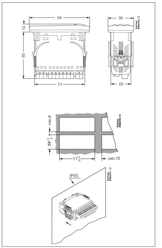
Encàrrec
Connexions
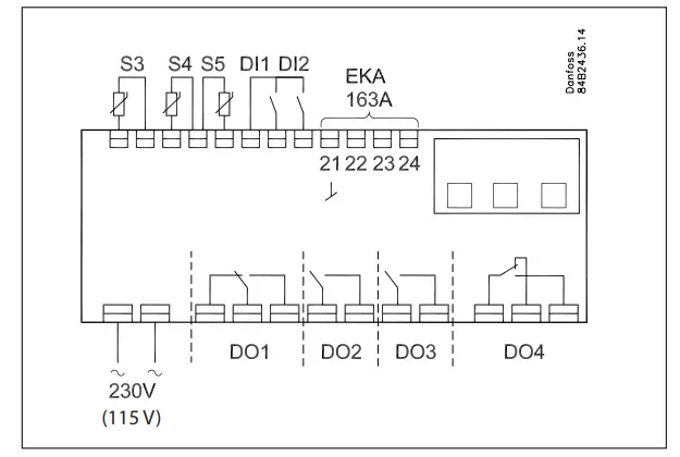
Font d'alimentació
230 V ac
Sensors
S3 i S4 són sensors de termòstat.
A setting determines whether S3 or S4 or both of them are to be used.
S5 is a defrost sensor and is used if defrost has to be stopped based on temperature.
Digital On/Off signals
Una entrada de tall activarà una funció. Les funcions possibles es descriuen als menús o02 i o37.
Pantalla externa
Connexió de pantalla tipus EKA 163A (EKA 164A).
Relleus
The general uses are mentioned here. See also page 6 where the different applications are shown.
- DO1: Refrigeration. The relay will cut in when the controller de-mands refrigeration
- DO2: Descongelació. El relé s'activarà quan la descongelació estigui en curs.
- DO3: For either fans or refrigeration 2
Fans: The relay will cut in when the fans have to operate Refrigeration 2: The relay will cut in when refrigeration step 2 has to be cut in - DO4: For either alarm, rail heat, light or hotgas defrost Alarm: Cf. diagram. The relay is cut in during normal opera-tion and cuts out in alarm situations and when the controller is dead (de-energised)
Rail heat: The relay cuts in when rail heat is to operate
Light: The relay cuts in when the light has to be switched on Hotgas defrost: See diagram. The relay will cut out when defrost has to be done
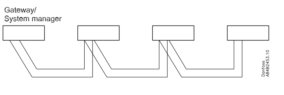
Comunicació de dades
The controller is available in several versions where data com-munication can be carried out with one of the following systems: MOD-bus or LON-RS485.
Si s'utilitza la comunicació de dades, és important que la instal·lació del cable de comunicació de dades es realitzi correctament.
Vegeu documentació separada núm. RC8AC...
Soroll elèctric
Els cables per als sensors, les entrades DI i la comunicació de dades s'han de mantenir separats dels altres cables elèctrics:
- Utilitzeu safates de cables separades
- Mantingueu una distància entre cables d'almenys 10 cm
- S'han d'evitar cables llargs a l'entrada DI
Descongelació coordinada mitjançant connexions de cable
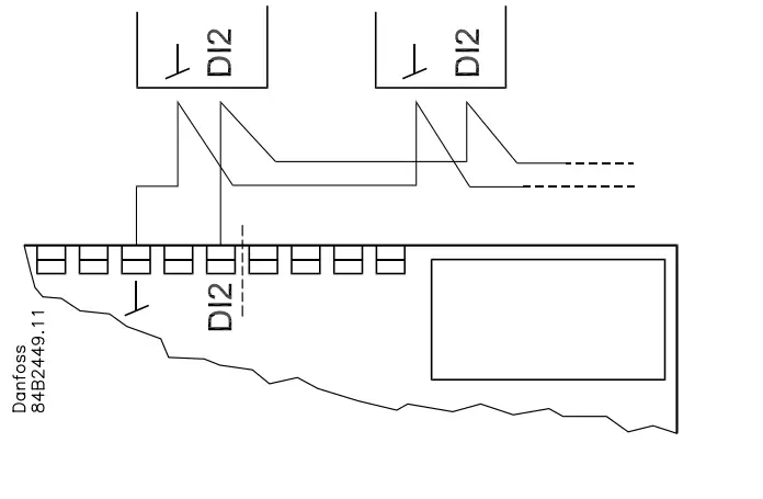
Els següents controladors es poden connectar d'aquesta manera:
- AK-CC 210, AK-CC 250, AK-CC 450,
AK-CC 550 - Max. 10.
La refrigeració es reprèn quan tots els controladors han "alliberat" el senyal de descongelació.
Descongelació coordinada mitjançant comunicació de dades
Dades
| Subministrament voltage | 230 V ac +10/-15 %. 2.5 VA, 50/60 Hz | ||
| Sensors 3 unitats apagats, qualsevol dels quals | Pt 1000 o
PTC 1000 o NTC-M2020 (5000 ohms / 25 °C) |
||
|
Precisió |
Interval de mesura | -60 a +99 °C | |
|
Controlador |
±1 K per sota de -35°C
±0.5 K entre -35 i +25°C ±1 K per sobre de +25°C |
||
| Sensor Pt 1000 | ±0.3 K a 0°C
±0.005 K per grau |
||
| Mostra | LED, 3 dígits | ||
| Pantalla externa | EKA 163A | ||
|
Entrades digitals |
Senyal de les funcions de contacte Requisits dels contactes: Revestiment d'or La longitud del cable ha de ser màxima. 15 m
Utilitzeu relés auxiliars quan el cable sigui més llarg |
||
| Electrical con- nection cable | Max.1,5 mm2 multi-core cable | ||
|
Relleus* |
CE
(250 V ca) |
UL *** (240 V CA) | |
| DO1.
Refrigeració |
8 (6) A | 10 A resistiu 5FLA, 30LRA | |
| DO2. Descongelació | 8 (6) A | 10 A resistiu 5FLA, 30LRA | |
|
DO3. Ventilador |
6 (3) A |
6 A resistiu 3FLA, 18LRA
131 VA Pilot deure |
|
|
DO4. Alarma |
4 (1) A
Mín. 100 mA** |
4 A resistent
131 Servei de pilot VA |
|
|
Ambients |
0 a +55 °C, Durant el funcionament
-40 a +70 °C, Durant el transport |
||
| 20 – 80% Rh, no condensat | |||
| Sense influència de xoc/vibracions | |||
| Densitat | IP 65 des del davant.
Els botons i l'embalatge estan incrustats a la part davantera. |
||
| Reserva d'escapament per al rellotge |
4 hores |
||
| Aprovacions
|
Vol baix de la UEtagLa directiva i les exigències de compatibilitat electromagnètica es compleixen amb el marcatge CE
LVD provat segons EN 60730-1 i EN 60730-2-9, A1, A2 EMC tested acc. EN61000-6-3 and EN 61000-6-2 |
||

- * DO1 and DO2 are 16 A relays. The mentioned 8 A can be increased up to 10 A, when the ambient temperature is kept below 50°C. DO3 and DO4 are 8 A relays. Max. load must be kept.
- ** El recobriment d'or garanteix el funcionament amb petites càrregues de contacte
- *** UL-approval based on 30000 couplings.
Danfoss no assumeix cap responsabilitat per possibles errors en catàlegs, fullets i altres materials imprès. Danfoss es reserva el dret d'alterar els seus productes sense previ avís. Això també s'aplica als productes ja en comanda, sempre que aquestes alternances es puguin fer sense que siguin necessaris canvis posteriors en les especificacions ja acordats.
Totes les marques registrades d'aquest material són propietat de les respectives empreses. Danfoss i el logotip de Danfoss són marques comercials de Danfoss A/S. Tots els drets reservats.
User Guide RS8EP602 © Danfoss 2018-11
Preguntes freqüents
- Q: How many thermostat sensors can be connected to the AK-CC 210 controller?
A: Up to two thermostat sensors can be connected. - Q: What functions can the digital inputs serve?
A: The digital inputs can be used for case cleaning, door contact with alarm, starting a defrost cycle, coordinated defrost, change-over between two temperature references, and retransmission of contact position via data communication.
Documents/Recursos
 |
Danfoss AK-CC 210 Controller For Temperature Control [pdfGuia de l'usuari AK-CC 210 Controller For Temperature Control, AK-CC 210, Controller For Temperature Control, For Temperature Control, Temperature Control |