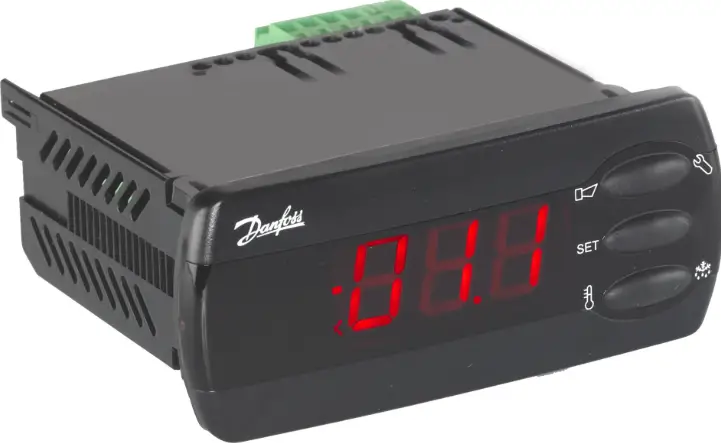
Danfoss AK-CC 210 Controller For Temperature Control
Specifications
- Product: Controller for temperature control AK-CC 210
- Maximum connected thermostat sensors: 2
- Digital inputs: 2
Introduction
Application
- The controller is used for temperature control refrigeration appliances in supermarkets
- With many predefined applications one unit will offer you many options. Flexibility has been planned both for new installations and for service in the refrigeration trade
Principle
The controller contains a temperature control where the signal can be received from one or two temperature sensors.
The thermostat sensors are either placed in the cold air flow after the evaporator, in the warm air flow just before the evaporator, or both. A setting will determine how great an influence the two signals are to have on the control.
A measurement of the defrost temperature can be obtained directly through the use of an S5 sensor or indirectly through the use of the S4 measurement. Four relays will cut the required functions in and out – the application determines which. The options are the following:
- Refrigeration (compressor or relay)
- Fan
- Defrost
- Rail heat
- Alarm
- Light
- Fans for hotgas defrost
- Refrigeration 2 (compressor 2 or relay 2)
The different applications are described on page 6.
Advantages
- Many applications in the same unit
- The controller has integrated refrigeration-technical functions, so that it can replace a whole collection of thermostats and timers
- Buttons and seal imbedded in the front
- Can control two compressors
- Easy to remount data communication
- Quick setup
- Two temperature references
- Digital inputs for various functions
- Clock function with super cap backup
- HACCP (Hazard Analysis and Critical Control Points)
- Temperature monitoring and registration of period with too high temperature (see also page 19)
- Factory calibration that will guarantee a better measuring accuracy than stated in the standard EN ISO 23953-2 without subsequent calibration (Pt 1000 ohm sensor)
Operation
Sensors
Up to two thermostat sensors can be connected to the controller. The relevant application determines how.
- A sensor in the air before the evaporator:
This connection is primarily used when control is based on area. - A sensor in the air after the evaporator:
This connection is primarily used when refrigeration is controlled and there is a risk of a too low temperature near the products. - A sensor before and after the evaporator:
This connection offers you the possibility of adapting the thermostat, the alarm thermostat and the display to the relevant application. The signal to the thermostat, the alarm thermostat and the display is set as a weighted value between the two temperatures, and 50% will for example give the same value from both sensors.
The signal to the thermostat, the alarm thermostat and the display can be set independently of one another. - Defrost sensor
The best signal concerning the evaporator’s temperature is obtained from a defrost sensor mounted directly on the evaporator. Here the signal may be used by the defrost function, so that the shortest and most energy-saving defrost can take place.
If a defrost sensor is not required, defrost can be stopped based on time, or S4 can be selected.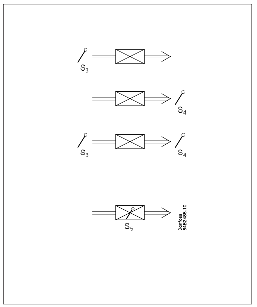
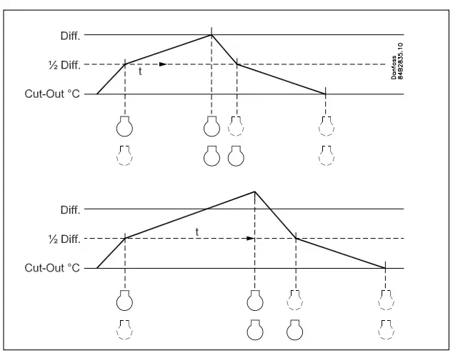
Control of two compressors
This control is used for controlling two compressors of the same size. The principle for control is that one of the compressors connects at ½ the differential of the thermostat, and the other at the full differential. When the thermostat cuts in the compressor with the fewest operating hours is started. The other compressor will only start after a set time delay, so that the load will be divided between them. The time delay has a higher priority than the temperature.
When the air temperature has dropped by half the differential the one compressor will stop, the other will continue working and not stop until the required temperature is achieved.
The compressors used must be of a type that is capable of starting up against a high pressure.
- Change of temperature reference
In an impulse appliance, for example, used for various product groups. Here the temperature reference is changed easily with a contact signal on a digital input. The signal raises the normal thermostat value by a predefined amount. At the same time the alarm limits with the same value are displaced accordingly.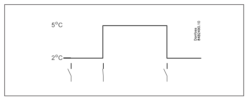
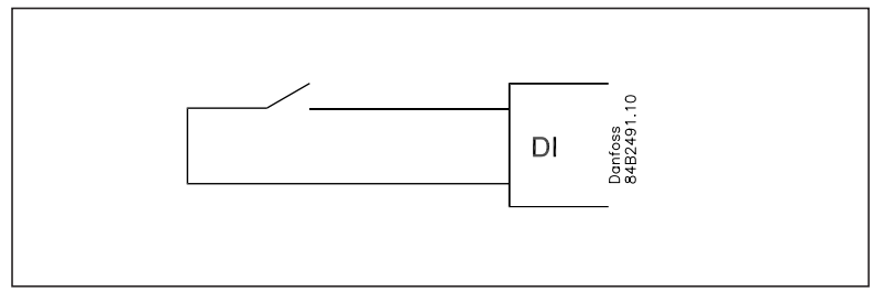
Digital inputs
There are two digital inputs both of which can be used for the following functions:
- Case cleaning
- Door contact function with alarm
- Starting a defrost
- Coordinated defrost
- Change-over between two temperature reference
- Retransmission of a contact’s position via data communication
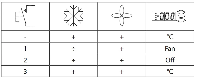
Case cleaning function
This function makes it easy to steer the refrigeration appliance through a cleaning phase. Via three pushes on a switch you change from one phase to the next phase.
The first push stops the refrigeration – the fans keep working
- ”Later”: The next push stops the fans
- ”Still later”: The next push restarts refrigeration
The different situations can be followed on the display.
On the network a cleaning alarm is transmitted to the system unit. This alarm can be ”logged” so that proof of the sequence of events is provided.
Door contact function
In cold rooms and frost rooms the door switch can switch the light on and off, start and stop the refrigeration and give alarm if the door has remained open for too long.

Defrost
Depending on the application you may choose between the following defrost methods:
- Natural: Here the fans are kept operating during the defrost
- Electric: The heating element is activated
- Brine: The valve is kept open so that the brine can flow through the evaporator
- Hotgas: Here the solenoid valves are controlled so that the hotgas can flow through the evaporator
Start of defrost
A defrost can be started in different ways
- Interval: Defrost is started at fixed time intervals, say, every eighth hour
- Refrigeration time:
Defrost is started at fixed refrigeration time intervals, in other words, a low need for refrigeration will ”postpone” the coming defrost - Schedule: Here defrost can be started at fixed times of the day and night. However, max. 6 times
- Contact: Defrost is started with a contact signal on a digital input
- Network: The signal for defrost is received from a system unit via the data communication
- S5 temp In 1:1 systems the efficiency of the evaporator can be followed. Icing-up will start a defrost.
- Manual: An extra defrost can be activated from the controller’s lower-most button. (Though not for application 4).
Coordinated defrost
There are two ways in which coordinated defrost can be arranged. Either with wire connections between the controllers or via data communication
Wire connections
One of the controllers is defined to be the controlling unit and a battery module may be fitted in it so that the clock is ensured backup. When a defrost is started all the other controllers will follow suit and likewise start a defrost. After the defrost the individual controllers will move into waiting position. When all are in waiting position there will be a change-over to refrigeration.
(If just one in the group demands defrost, the others will follow suit).
Defrost via data communication
All controllers are fitted with a data communication module, and via the override function from a gateway the defrost can be coordinated.
Defrost on demand
- Based on refrigeration time
When the aggregate refrigeration time has passed a fixed time, a defrost will be started. 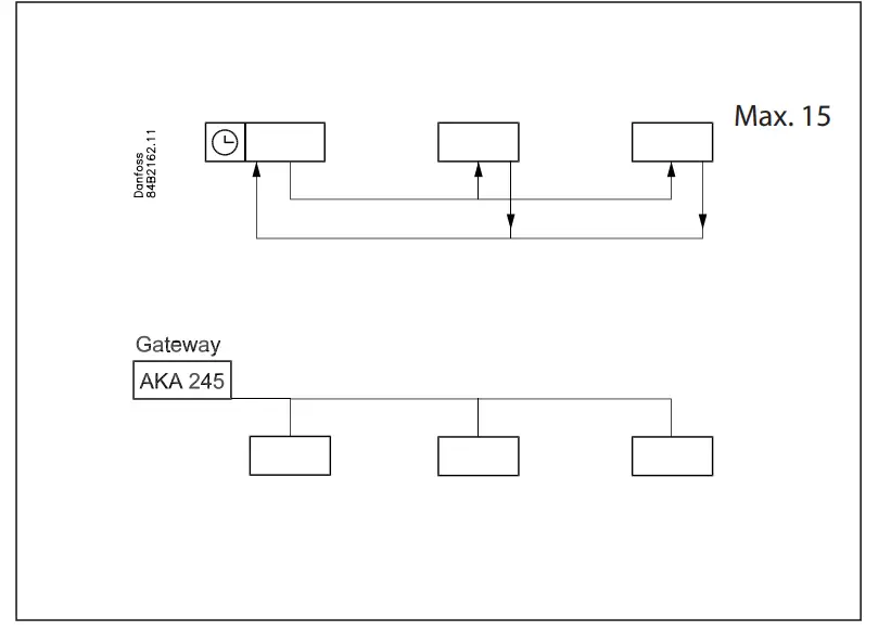 Based on temperature
The controller will constantly follow the temperature at S5. Between two defrosts the S5 temperature will become lower the more the evaporator ices up (the compressor operates for a longer time and pulls the S5 temperature further down). When the temperature passes a set allowed variation the defrost will be started.
This function can only work in 1:1 systems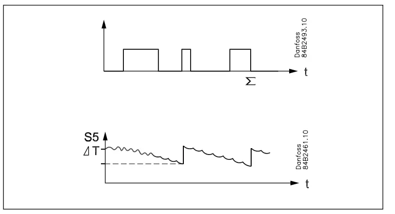
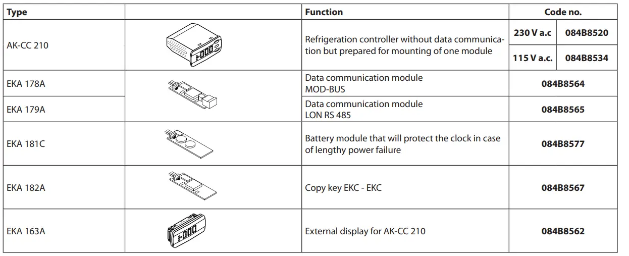
Extra module
- The controller can afterwards be fitted with an insertion module if the application requires it.
The controller has been prepared with plug, so the module simply has to be pushed in- Battery module
The module guarantees voltage to the controller if the supply voltage should drop out for more than four hours. The clock function can thus be protected during a power failure. - Data communication
If you require operation from a PC, a data communication module has to be placed in the controller.
- Battery module
- External display
If it is necessary to indicate the temperature on the front of refrigeration appliance, a display type EKA 163A can be mounted. The extra display will show the same information as the control-ler’s display, but does not incorporate buttons for operation. If operation from the external display is needed a display type EKA 164A must be mounted.

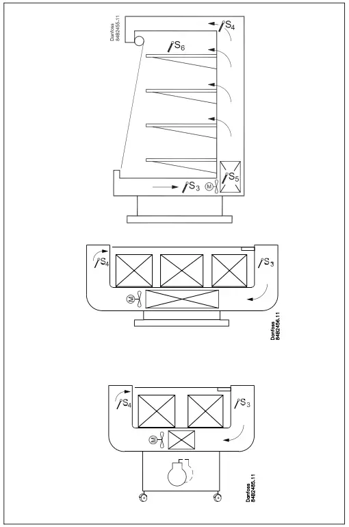
Applications
Here is a survey of the controller’s field of application.
- A setting will define the relay outputs so that the controller’s interface will be targeted to the chosen application.
- On page 20 you can see the relevant settings for the respective wiring diagrams.
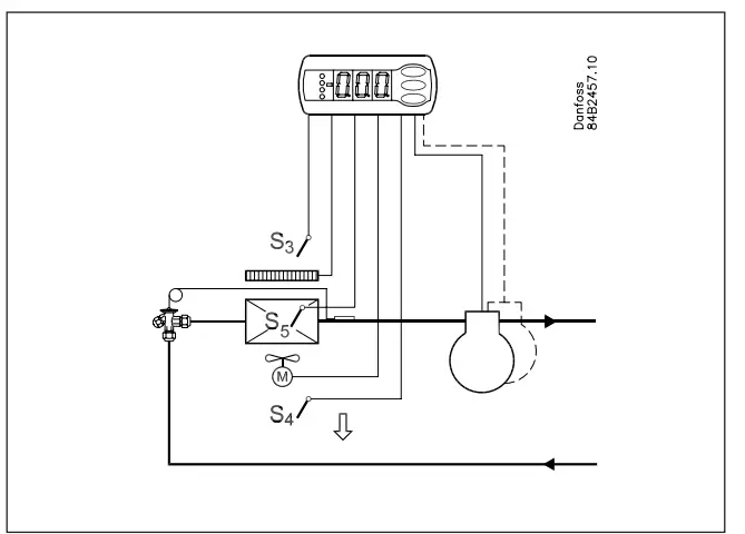
- S3 and S4 are temperature sensors. The application will deter-mine whether either one or the other or both sensors are to be used. S3 is placed in the air flow before the evaporator. S4 after the evaporator.
- A percentage setting will determine according to what the control is to be based. S5 is a defrost sensor and is placed on the evaporator.
- DI1 and DI2 are contact functions that can be used for one of the following functions: door function, alarm function, defrost start, external main switch, night operation, change of thermostat reference, appliance cleaning, forced refrigeration or coordinated defrost. See the functions in settings o02 and o37.
Refrigeration control with one compressor
The functions are adapted to small refrigeration systems which either may be refrigeration appliances or cold rooms.
The three relays can control the refrigeration, the defrost and the fans, and the fourth relay can be used for either alarm function, light control or rail heat control
- The alarm function can be linked up with a contact function from a door switch. If the door remains open longer than al-lowed there will be an alarm.
- The light control can also be linked up with a contact function from a door switch. An open door will switch on the light and it will remain lit for two minutes after the door has been closed again.
- The rail heat function can be used in refrigeration or freezing appliances or on the door’s heating element for frost rooms.
The fans can be stopped during defrost and they may also follow a door switch’s open/close situation.
There are several other functions for the alarm function as well as the light control, rail heat control and fans. Please refer to the respective settings.
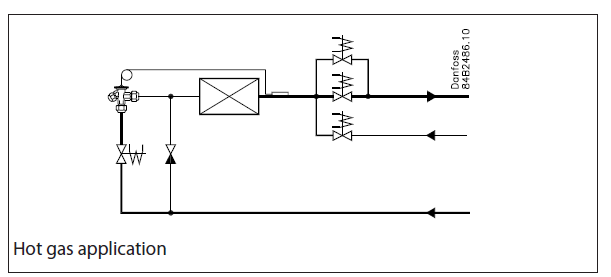
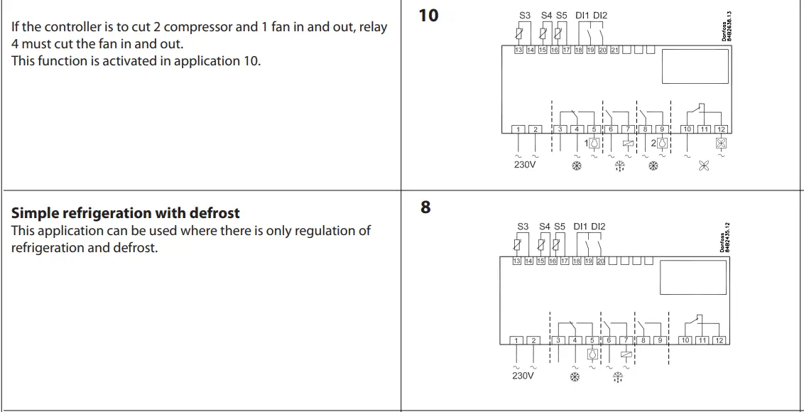
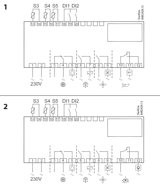 Hot gas defrost
This type of connection can be used on systems with hotgas defrost, but only in small systems in, say, supermarkets – the functional content has not been adapted to systems with large charges. Relay 1’s change-over function can be used by the bypass valve and/or the hotgas valve.
Relay 2 is used for refrigeration.


Survey of functions
| Function | Para- meter | Parameter by operation via data communication |
| Normal display | ||
| Normally the temperature value from one of the two thermostat sensors S3 or S4 or a mixture of the two measurements is displayed.
In o17 the ratio is determined. |
Display air (u56) | |
| Thermostat | Thermostat control | |
| Set point
Regulation is based on the set value plus a displacement, if applicable. The value is set via a push on the centre button. The set value can be locked or limited to a range with the settings in r02 and r 03. The reference at any time can be seen in ”u28 Temp. ref” |
Cutout °C | |
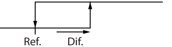
| Differential
When the temperature is higher than the reference + the set differential, the com- pressor relay will be cut in. It will cut out again when the temperature comes down to the set reference. |
r01 | Differential |
| Setpoint limitation
The controller’s setting range for the setpoint may be narrowed down, so that much too high or much too low values are not set accidentally – with resulting damages. |
||
| To avoid a too high setting of the setpoint, the max. allowable reference value must be lowered. | r02 | Max cutout °C |
| To avoid a too low setting of the setpoint, the min. allowable reference value must be increased. | r03 | Min cutout °C |
| Correction of the display’s temperature showing
If the temperature at the products and the temperature received by the controller are not identical, an offset adjustment of the shown display temperature can be carried out. |
r04 | Disp. Adj. K |
| Temperature unit
Set here if the controller is to show temperature values in °C or in °F. |
r05 | Temp. unit
°C=0. / °F=1 (Only °C on AKM, whatever the set- ting) |
| Correction of signal from S4
Compensation possibility through long sensor cable |
r09 | Adjust S4 |
| Correction of signal from S3
Compensation possibility through long sensor cable |
r10 | Adjust S3 |
| Start / stop of refrigeration
With this setting refrigeration can be started, stopped or a manual override of the outputs can be allowed. Start / stop of refrigeration can also be accomplished with the external switch func- tion connected to a DI input. Stopped refrigeration will give a ”Standby alarm”. |
r12 | Main Switch
1: Start 0: Stop -1: Manual control of outputs allowed |
| Night setback value
The thermostat’s reference will be the setpoint plus this value when the controller changes over to night operation. (Select a negative value if there is to be cold ac- cumulation.) |
r13 | Night offset |
| Selection of thermostat sensor
Here you define the sensor the thermostat is to use for its control function. S3, S4, or a combination of them. With the setting 0%, only S3 is used (Sin). With 100%, only S4. (For application 9 an S3 sensor must be used) |
r15 | Ther. S4 % |
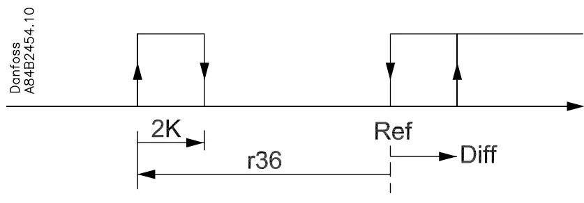
| Heating function
The function uses the defrost function’s heating element for raising the temperature. The function enters into force a number of degrees (r36) below the actual reference and cuts out again with a differential of 2 degrees. Regulation is carried out with 100% signal from the S3 sensor. The fans will be operating when there is heating. The fans and the heating function will stop if door function has been selected and the door is opened. Where this function is used an external safety cutout should also be installed, so that superheating of the heating element cannot take place. Remember to set D01 to electrical defrosting. |
r36 | HeatStartRel |
| Activation of reference displacement
When the function is changed to ON the thermostat reference will be displaced by the value in r40. Activation can also take place via input DI1 or DI2 (defined in o02 or o37). |
r39 | Th. offset |
| Value of reference displacement
The thermostat reference and the alarm values are shifted the following number of degrees when the displacement is activated. Activation can take place via r39 or input DI |
r40 | Th. offset K |
| Night setbck (start of night signal) | ||
| Forced cool.
(start of forced cooling) |
||
| Alarm | Alarm settings | |
| The controller can give alarm in different situations. When there is an alarm all the light-emitting diodes (LED) will flash on the controller front panel, and the alarm relay will cut in. | With data communication the impor- tance of the individual alarms can be defined. Setting is carried out in the “Alarm destinations” menu. | |
| Alarm delay (short alarm delay)
If one of the two limit values is exceeded, a timer function will commence. The alarm will not become active until the set time delay has been passed. The time delay is set in minutes. |
A03 | Alarm delay |
| Time delay for door alarm
The time delay is set in minutes. The function is defined in o02 or in o37. |
A04 | DoorOpen del |
| Time delay for cooling (long alarm delay)
This time delay is used during start-up, during defrost, immediately after a defrost. There will be change-over to the normal time delay (A03) when the temperature has dropped below the set upper alarm limit. The time delay is set in minutes. |
A12 | Pulldown del |
| Upper alarm limit
Here you set when the alarm for high temperature is to start. The limit value is set in °C (absolute value). The limit value will be raised during night operation. The value is the same as the one set for night setback, but will only be raised if the value is positive. The limit value will also be raised in connection with reference displacement r39. |
A13 | HighLim Air |
| Lower alarm limit
Here you set when the alarm for low temperature is to start. The limit value is set in °C (absolute value). The limit value will also be raised in connection with reference displacement r39. |
A14 | LowLim Air |
| Delay of a DI1 alarm
A cut-out/cut-in input will result in alarm when the time delay has been passed. The function is defined in o02. |
A27 | AI.Delay DI1 |
| Delay of a DI2 alarm
A cut-out/cut-in input will result in alarm when the time delay has been passed. The function is defined in o37 |
A28 | AI.Delay DI2 |
| Signal to the alarm thermostat
Here you have to define the ratio between the sensors which the alarm thermostat has to use. S3, S4 or a combination of the two. With setting 0% only S3 is used. With 100% only S4 is used |
A36 | Alarm S4% |
| Reset alarm | ||
| EKC error |

| Compressor | Compressor control | |
| The compressor relay works in conjunction with the thermostat. When the thermo- stat calls for refrigeration will the compressor relay be operated. | ||
| Running times
To prevent irregular operation, values can be set for the time the compressor is to run once it has been started. And for how long it at least has to be stopped. The running times are not observed when defrosts start. |
||
| Min. ON-time (in minutes) | c01 | Min. On time |
| Min. OFF-time (in minutes) | c02 | Min. Off time |
| Time delay for couplings of two compressors
Settings indicate the time that has to elapse from the first relay cuts in and until the next relay has to cut in. |
c05 | Step delay |
| Reversed relay function for D01
0: Normal function where the relay cuts in when refrigeration is demanded 1: Reversed function where the relay cuts out when refrigeration is demanded (this wiring produces the result that there will be refrigeration if the supply voltage to the controller fails). |
c30 | Cmp relay NC |
| The LED on the controller’s front will show whether refrigeration is in progress. | Comp Relay
Here you can read the status of the compressor relay, or you can force- control the relay in the ”Manual control” mode |
|
| Defrost | Defrost control | |
|
||
Defrost method
|
d01 | Def. method 0 = non
1 = El 2 = Gas 3= Brine |
| Defrost stop temperature
The defrost is stopped at a given temperature which is measured with a sensor (the sensor is defined in d10). The temperature value is set. |
d02 | Def. Stop Temp |
Interval between defrost starts
|
d03 | Def Interval (0=off) |
| Max. defrost duration
This setting is a safety time so that the defrost will be stopped if there has not already been a stop based on temperature or via coordinated defrost. |
d04 | Max Def. time |
Time staggering for defrost cut ins during start-up
|
d05 | Time Stagg. |
| Drip-off time
Here you set the time that is to elapse from a defrost and until the compressor is to start again. (The time when water drips off the evaporator). |
d06 | DripOff time |
| Delay of fan start after defrost
Here you set the time that is to elapse from compressor start after a defrost and until the fan may start again. (The time when water is “tied” to the evaporator). |
d07 | FanStartDel |
| Fan start temperature
The fan may also be started a little earlier than mentioned under “Delay of fan start after defrost”, if the defrost sensor S5 registers a lower value than the one set here. |
d08 | FanStartTemp |
| Fan cut in during defrost
Here you can set whether fan is to operate during defrost. 0: Stopped (Runs during pump down)
|
d09 | FanDuringDef |
| Defrost sensor
Here you define the defrost sensor. 0: None, defrost is based on time 1: S5 2: S4 |
d10 | DefStopSens. |
| Pumpdown delay
Set the time where the evaporator is emptied of refrigerant prior to the defrost. |
d16 | Pump dwn del. |
| Drain delay (only in connection with hotgas)
Set the time where the evaporator is emptied of condensed refrigerant after the defrost. |
d17 | Drain del |
| Defrost on demand – aggregate refrigeration time
Set here is the refrigeration time allowed without defrosts. If the time is passed, a defrost will be started. With setting = 0 the function is cut out. |
d18 | MaxTherRunT |
| Defrost on demand – S5 temperature
The controller will follow the effectivity of the evaporator, and via internal calcula- tions and measurements of the S5 temperature it will be able to start a defrost when the variation of the S5 temperature becomes larger than required. Here you set how large a slide of the S5 temperature can be allowed. When the value is passed, a defrost will start. The function can only be used in 1:1 systems when the evaporating temperature will become lower to ensure that the air temperature will be maintained. In central systems the function must be cut out. With setting = 20 the function is cut out |
d19 | CutoutS5Dif. |
| Delay of the hot gas injection
Can be used when vales of the type PMLX and GPLX are used. Time is set so that the valve is closed completely before the hot gas is turned on. |
d23 | — |
| If you wish to see the temperature at the defrost sensor, push the controller’s lower- most button. | Defrost temp. | |
| If you wish to start an extra defrost, push the controller’s lowermost button for four seconds.
You can stop an ongoing defrost in the same way |
Def Start
Here you can start a manual defrost |
|
| The LED on the controller’s front will indicate whether a defrost is going on. | Defrost Relay
Here you can read the defrost relay status or you can force-control the relay in “Manual control” mode. |
|
| Hold After Def
Shows ON when the controller is operating with coordinated defrost. |
||
| Defrost State Status on defrost
1= pump down / defrost |
||
| Fan | Fan control | |
| Fan stopped at cut-out compressor
Here you can select whether the fan is to be stopped when the compressor is cut out |
F01 | Fan stop CO
(Yes = Fan stopped) |
| Delay of fan stop when compressor is cut out
If you have chosen to stop the fan when the compressor is cut out, you can delay the fan stop when the compressor has stopped. Here you can set the time delay. |
F02 | Fan del. CO |
| Fan stop temperature
The function stops the fans in an error situation, so that they will not provide power to the appliance. If the defrost sensor registers a higher temperature than the one set here, the fans will be stopped. There will be re-start at 2 K below the setting. The function is not active during a defrost or start-up after a defrost. With setting +50°C the function is interrupted. |
F04 | FanStopTemp. |
| The LED on the controller’s front will indicate whether the fan is running. | Fan Relay
Here you can read the fan relay status, or force-control the relay in “Manual control” mode. |
| HACCP | HACCP | |
| HACCP temperature
Here you can see the temperature measurement that transmits signal to the function |
h01 | HACCP temp. |
| Last too high HACCP temperature was registered in connection with: (Value can be read out).
H01: Temperature exceeding during normal regulation. H02: Temperature exceeding during power failure. Battery backup controls the times. H03: Temperature exceeding during power failure. No control of times. |
h02 | – |
| Last time the HACCP temperature was exceeded: Year | h03 | – |
| Last time the HACCP temperature was exceeded: Month | h04 | – |
| Last time the HACCP temperature was exceeded: Day | h05 | – |
| Last time the HACCP temperature was exceeded: Hour | h06 | – |
| Last time the HACCP temperature was exceeded: Minute | h07 | – |
| Last exceeding: Duration in hours | h08 | – |
| Last exceeding: Duration in minutes | h09 | – |
| Peak temperature
The highest measured temperature will continuously be saved when the temperature exceeds the limit value in h12. The value can be read out until the next time the tem- perature exceeds the limit value. After that it is overwritten with the new measure- ments. |
h10 | Max.temp. |
| Selection of function 0: No HACCP function
1: S3 and/or S4 used as sensor. Definition takes place in h14. 2: S5 used as sensor. |
h11 | HACCP sensor |
| Alarm limit
Here you set the temperature value at which the HACCP function is to enter into force. When the value becomes higher than the set one, the time delay starts. |
h12 | HACCP limit |
| Time delay for the alarm (only during normal regulation). When the time delay has been passed the alarm is activated. | h13 | HACCP delay |
| Selection of sensors for the measuring
If the S4 sensor and/or the S3 sensor is used, the ratio between them must be set. At setting 100% only S4 is used. At setting 0% only S3 is used. |
h14 | HACCP S4% |
| Internal defrosting schedule/clock function | ||
| (Not used if an external defrosting schedule is used via data communication.) Up to six individual times can be set for the defrost start throughout the day. | ||
| Defrost start, hour setting | t01-t06 | |
| Defrost start, minute setting (1 and 11 belong together, etc.) When all t01 to t16 equal 0 the clock will not start defrosts. | t11-t16 | |
| Real-time clock
Setting the clock is only necessary when there is no data communication. In the event of a power failure of less than four hours, the clock function will be saved. When mounting a battery module the clock function can preserved longer. There is also a date indication used for registration of temperature measurements. |
||
| Clock: Hour setting | t07 | |
| Clock: Minute setting | t08 | |
| Clock: Date setting | t45 | |
| Clock: Month setting | t46 | |
| Clock: Year setting | t47 | |
| Miscellaneous | Miscellaneous | |
| Delay of output signal after start-up
Start-up after a power failure the controller’s functions can be delayed so that over- loading of the electricity supply network is avoided. Here you can set the time delay. |
o01 | DelayOfOutp. |
| Digital input signal – DI1
The controller has a digital input 1 which can be used for one of the following func- tions: Off: The input is not used
|
o02 | DI 1 Config.
Definition takes place with the nu- merical value shown to the left.
(0 = off)
DI state (Measurement) The DI input’s present status is shown here. ON or OFF. |
|
After installation of a data communi- cation module the controller can be operated on an equal footing with the other controllers in ADAP-KOOL® refrigeration controls. | |
| o03 | ||
| o04 | ||
| Access code 1 (Access to all settings)
If the settings in the controller are to be protected with an access code you can set a numerical value between 0 and 100. If not, you can cancel the function with setting 0. (99 will always give you access). |
o05 | – |
| Sensor type
Normally a Pt 1000 sensor with great signal accuracy is used. But you can also use a sensor with another signal accuracy. That may either be a PTC 1000 sensor (1000 ohm) or an NTC sensor (5000 Ohm at 25°C). All the mounted sensors must be of the same type. |
o06 | SensorConfig Pt = 0
PTC = 1 NTC = 2 |
| Display step
Yes: Gives steps of 0.5° No: Gives steps of 0.1° |
o15 | Disp. Step = 0.5 |
| Max. standby time after coordinated defrost
When a controller has completed a defrost it will wait for a signal which tells that the refrigeration may be resumed. If this signal fails to appear for one reason or another, the controller will itself start the refrigeration when this standby time has elapsed. |
o16 | Max HoldTime |
| Select signal for the display S4%
Here you define the signal to be shown by the display. S3, S4, or a combination of the two. With setting 0% only S3 is used. With 100% only S4. |
o17 | Disp. S4% |
| Digital input signal – D2
The controller has a digital input 2 which can be used for one of the following func- tions: Off: The input is not used.
|
o37 | DI2 config. |
Configuration of light function (relay 4 in applications 2 and 6)
|
o38 | Light config |
| Activation of light relay
The light relay can be activated here, but only if defined in o38 with setting 2. |
o39 | Light remote |
| Rail heat during day operation
The ON period is set as a percentage of the time |
o41 | Railh.ON day% |
| Rail heat during night operation
The ON period is set as a percentage of the time |
o42 | Railh.ON ngt% |
| Rail heat cycle
The period of time for the aggregate ON time + OFF time is set in minutes |
o43 | Railh. cycle |
Case cleaning
If the function is controlled by a signal at the DI1 or DI2 input, the relevant status can be seen here in the menu. |
o46 | Case clean |
| Selection of application
The controller can be defined in various ways. Here you set which of the 10 applica- tions is required. On page 6 you can see a survey of applications. This menu can only be set when regulation is stopped, i.e. “r12” is set to 0. |
o61 | — Appl. Mode (only output in Danfoss only) |
| Transfer a set of presetting to the controller
It is possible to select a quick setting of a number of parameters. It depends on whether an application or a room is to be controlled and whether defrost is to be stopped based on time or based on temperature. The survey can be seen on page 22. This menu can only be set when regulation is stopped, i.e. “r12” is set to 0.
After the setting the value will return to 0. Any subsequent adjustment/setting of parameters can be made, as required. |
o62 | – |
| Access code 2 (Access to adjustments)
There is access to adjustments of values, but not to configuration settings. If the set- tings in the controller are to be protected with an access code you can set a numeri- cal value between 0 and 100. If not, you can cancel the function with setting 0. If the function is used, access code 1 (o05) must also be used. |
o64 | – |
| Copy the controller’s present settings
With this function the controller’s settings can be transferred to a programming key. The key can contain up to 25 different sets. Select a number. All settings except for Application (o61) and Address (o03) will be copied. When copying has started the dis- play returns to o65. After two seconds you can move into the menu again and check whether the copying was satisfactory. Showing of a negative figure spells problems. See the significance in the Fault Mes- sage section. |
o65 | – |
| Copy from the programming key
This function downloads a set of settings earlier saved in the controller. Select the relevant number. All settings except for Application (o61) and Address (o03) will be copied. When copy- ing has started the display returns to o66. After two seconds you can move back into the menu again and check whether the copying was satisfactory. Showing of a nega- tive figure spells problems. See the significance in the Fault Message section. |
o66 | – |
| Save as factory setting
With this setting you save the controller’s actual settings as a new basic setting (the earlier factory settings are overwritten). |
o67 | – |
| – – – Night Setback 0=Day
1=Night |
| Service | Service | |
| Temperature measured with S5 sensor | u09 | S5 temp. |
| Status on DI1 input. on/1=closed | u10 | DI1 status |
| Temperature measured with S3 sensor | u12 | S3 air temp |
| Status on night operation (on or off) 1=closed | u13 | Night Cond. |
| Temperature measured with S4 sensor | u16 | S4 air temp |
| Thermostat temperature | u17 | Ther. air |
| Read the present regulation reference | u28 | Temp. ref. |
| Status on DI2 output. on/1=closed | u37 | DI2 status |
| Temperature shown on display | u56 | Display air |
| Measured temperature for alarm thermostat | u57 | Alarm air |
| ** Status on relay for cooling | u58 | Comp1/LLSV |
| ** Status on relay for fan | u59 | Fan relay |
| ** Status on relay for defrost | u60 | Def. relay |
| ** Status on relay for railheat | u61 | Railh. relay |
| ** Status on relay for alarm | u62 | Alarm relay |
| ** Status on relay for light | u63 | Light relay |
| ** Status on relay for valve in suction line | u64 | SuctionValve |
| ** Status on relay for compressor 2 | u67 | Comp2 relay |
| *) Not all items will be shown. Only the function belonging to the selected applica- tion can be seen. |
| Fault message | Alarms | |
| In an error situation the LED’s on the front will flash and the alarm relay will be acti- vated. If you push the top button in this situation you can see the alarm report in the display. If there are more keep on pushing to see them.
There are two kinds of error reports – it can either be an alarm occurring during the daily operation, or there may be a defect in the installation. A-alarms will not become visible until the set time delay has expired. E-alarms, on the other hand, will become visible the moment the error occurs. (An A alarm will not be visible as long as there is an active E alarm). Here are the messages that may appear: |
1 = alarm |
|
| A1: High temperature alarm | High t. alarm | |
| A2: Low temperature alarm | Low t. alarm | |
| A4: Door alarm | Door Alarm | |
| A5: Information. Parameter o16 is expired | Max Hold Time | |
| A15: Alarm. Signal from DI1 input | DI1 alarm | |
| A16: Alarm. Signal from DI2 input | DI2 alarm | |
| A45: Standby position (stopped refrigeration via r12 or DI input) (Alarm relay will not be activated) | Standby mode | |
| A59: Case cleaning. Signal from DI1 or DI2 input | Case cleaning | |
| A60: High-temperature alarm for the HACCP function | HACCP alarm | |
| Max. def time | ||
| E1: Faults in the controller | EKC error | |
| E6: Fault in real-time clock. Check the battery / reset the clock. | – | |
| E25: Sensor error on S3 | S3 error | |
| E26: Sensor error on S4 | S4 error | |
| E27: Sensor error on S5 | S5 error | |
When copying settings to or from a copying key with functions o65 or o66, the fol- lowing information may appear:
(The information can be found in o65 or o66 a couple of seconds after copying has been started). |
||
| Alarm destinations | ||
| The importance of the individual alarms can be defined with a setting (0, 1, 2 or 3) |
| Operating status | (Measurement) | |
| The controller goes through some regulating situations where it is just waiting for the next point of the regulation. To make these “why is nothing happening” situations
visible, you can see an operating status on the display. Push briefly (1s) the upper but- ton. If there is a status code, it will be shown on the display. The individual status codes have the following meanings: |
EKC State:
(Shown in all menu displays) |
|
| S0: Regulating | 0 | |
| S1: Waiting for end of the coordinated defrost | 1 | |
| S2: When the compressor is operating it must run for at least x minutes. | 2 | |
| S3: When the compressor is stopped, it must remain stopped for at least x minutes. | 3 | |
| S4: The evaporator drips off and waits for the time to run out | 4 | |
| S10: Refrigeration stopped by main switch. Either with r12 or a DI-input | 10 | |
| S11: Refrigeration stopped by thermostat | 11 | |
| S14: Defrost sequence. Defrost in progress | 14 | |
| S15: Defrost sequence. Fan delay — water attaches to the evaporator | 15 | |
| S17: Door is open. DI input is open | 17 | |
| S20: Emergency cooling *) | 20 | |
| S25: Manual control of outputs | 25 | |
| S29: Case cleaning | 29 | |
| S30: Forced cooling | 30 | |
| S32: Delay on outputs during start-up | 32 | |
| S33: Heat function r36 is active | 33 | |
| Other displays: | ||
| non: The defrost temperature cannot be displayed. There is stop based on time | ||
| -d-: Defrost in progress / First cooling after defrost | ||
| PS: Password required. Set password |
*) Emergency cooling will take effect when there is lack of signal from a defined S3 or S4 sensor. The regulation will continue with a registered average cutin frequency. There are two registered values – one for day operation and one for night operation.
Warning ! Direct start of compressors *
To prevent compressor breakdown parameter c01 and c02 should be set according to suppliers requirements or in general : Hermetic Compressors c02 min. 5 minutes
Semihermetic Compressors c02 min. 8 minutes and c01 min. 2 to 5 minutes ( Motor from 5 to 15 KW )
* ) Direct activating of solenoid valves does not require settings different from factory (0)
Operation
Display
The values will be shown with three digits, and with a setting you can determine whether the temperature are to be shown in °C or in °F.
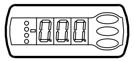
Light-emitting diodes (LED) on front panel
HACCP = HACCP function is active
The other LED’s on the front panel will light up when the belong-ing relay is activated.

The light-emitting diodes will flash when there is an alarm.
In this situation you can download the error code to the display and cancel/sign for the alarm by giving the top knob a brief push.
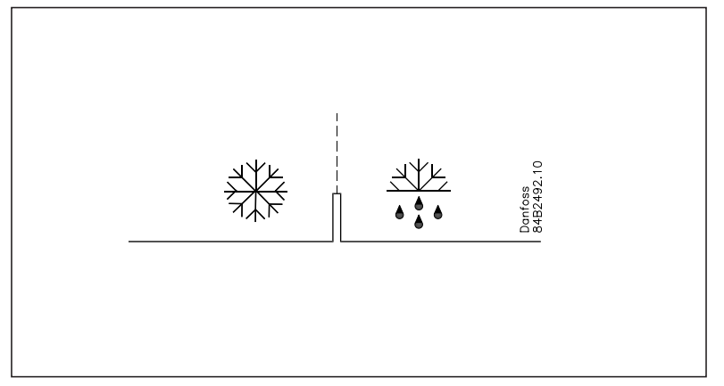
Defrost
During defrost a –d- is shown in the display. This view will con-tinue up till 15 min. after the cooling has resumed.
However the view of –d- will be discontinued if:
- The temperature is suitable within the 15 minutes
- The regulation is stopped with “Main Switch”
- A high temperature alarm appears
The buttons
When you want to change a setting, the upper and the lower buttons will give you a higher or lower value depending on the button you are pushing. But before you change the value, you must have access to the menu. You obtain this by pushing the upper button for a couple of seconds – you will then enter the col-umn with parameter codes. Find the parameter code you want to change and push the middle buttons until value for the parameter is shown. When you have changed the value, save the new value by once more pushing the middle button.
Examples
Set menu
- Push the upper button until a parameter r01 is shown
- Push the upper or the lower button and find that parameter you want to change
- Push the middle button until the parameter value is shown
- Push the upper or the lower button and select the new value
- Push the middle button again to freeze the value.
Cutout alarm relay / receipt alarm/see alarm code
- Push short the upper button
If there are several alarm codes they are found in a rolling stack. Push the uppermost or lowermost button to scan the rolling stack.
Set temperature
- Push the middle button until the temperature value is shown
- Push the upper or the lower button and select the new value
- Push the middle button again to conclude the setting.
Reading the temperature at defrost sensor
Push short the lower button
Manuel start or stop of a defrost
Push the lower button for four seconds.(Though not for application 4).
See HACCP registration
- Give the middle button a long push until h01 appears
- Select required h01-h10
- See value by giving the middle button a short push
Get a good start
With the following procedure you can start regulation very quick-ly:
- Open parameter r12 and stop the regulation (in a new and not previously set unit, r12 will already be set to 0 which means stopped regulation.)
- Select electric connection based on the drawings on page 6
- Open parameter o61 and set the electric connection number in it
- Now select one of the preset settings from the table on page 22.
- Open parameter o62 and set the number for the array of preset- tings. The few selected settings will now be transferred to the menu.
- Open parameter r12 and start the regulation
- Go through the survey of factory settings. The values in the grey cells are changed according to your choice of settings. Make any necessary changes in the respective parameters.
- For network. Set the address in o03 and then transmit it to the gateway/system unit with setting o04.
HACCP
This function will follow the appliance temperature and sound an alarm if the set temperature limit is exceeded. The alarm will come when the time delay has elapsed.
When the temperature exceeds the limit value it will continuously be registered and the peak value will be saved until the later rea-dout. Saved together with the value will be the time and duration of the temperature exceeding.
Examples of temperature exceeding:
Exceeding during normal regulation

Exceeding in connection with power failure where the controller can keep on registering the time performance.

Exceeding in connection with power failure when the controller has lost its clock function and hence also its time performance.
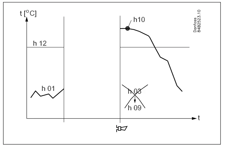
The readout of the various values in the HACCP function can take place with a long push on the middle button.
The readouts are, as follows:
- h01: The temperature
- h02: Readout of the controller’s status when temperature was exceeded:
- H1 = normal regulation.
- H2 = power failure. Times are saved.
- H3 = power failure. Times not saved.
- h03: Time. Year
- h04: Time. Month
- h05: Time: Day
- h06: Time. Hour
- h07: Time. Minute
- h08: Duration in hours
- h09: Duration in minutes
- h10: The registered peak temperature
(Setup of the function takes place just like the other setups. See menu survey on the next page).
| Parameters | EL-diagram number (page 6) | Min.-
value |
Max.-
value |
Factory
setting |
Actual
setting |
|||||||||||
| Function | Codes | 1 | 2 | 3 | 4 | 5 | 6 | 7 | 8 | 9 | 10 | |||||
| Normal operation | ||||||||||||||||
| Temperature (set point) | — | -50.0°C | 50.0°C | 2.0°C | ||||||||||||
| Thermostat | ||||||||||||||||
| Differential | *** | r01 | 0.1 K | 20.0K | 2.0 K | |||||||||||
| Max. limitation of setpoint setting | *** | r02 | -49.0°C | 50°C | 50.0°C | |||||||||||
| Min. limitation of setpoint setting | *** | r03 | -50.0°C | 49.0°C | -50.0°C | |||||||||||
| Adjustment of temperature indication | r04 | -20.0 K | 20.0 K | 0.0 K | ||||||||||||
| Temperature unit (°C/°F) | r05 | °C | °F | °C | ||||||||||||
| Correction of the signal from S4 | r09 | -10.0 K | +10.0 K | 0.0 K | ||||||||||||
| Correction of the signal from S3 | r10 | -10.0 K | +10.0 K | 0.0 K | ||||||||||||
| Manual service, stop regulation, start regulation (-1, 0, 1) | r12 | -1 | 1 | 0 | ||||||||||||
| Displacement of reference during night operation | r13 | -10.0 K | 10.0 K | 0.0 K | ||||||||||||
| Definition and weighting, if applicable, of thermostat sensors
– S4% (100%=S4, 0%=S3) |
r15 | 0% | 100% | 100% | ||||||||||||
| The heating function is started a number of degrees below the
thermostats cutout temperature |
r36 | -15.0 K | -3.0 K | -15.0 K | ||||||||||||
| Activation of reference displacement r40 | r39 | OFF | ON | OFF | ||||||||||||
| Value of reference displacement (activate via r39 or DI) | r40 | -50.0 K | 50.0 K | 0.0 K | ||||||||||||
| Alarm | ||||||||||||||||
| Delay for temperature alarm | A03 | 0 min | 240 min | 30 min | ||||||||||||
| Delay for door alarm | *** | A04 | 0 min | 240 min | 60 min | |||||||||||
| Delay for temperature alarm after defrost | A12 | 0 min | 240 min | 90 min | ||||||||||||
| High alarm limit | *** | A13 | -50.0°C | 50.0°C | 8.0°C | |||||||||||
| Low alarm limit | *** | A14 | -50.0°C | 50.0°C | -30.0°C | |||||||||||
| Alarm delay DI1 | A27 | 0 min | 240 min | 30 min | ||||||||||||
| Alarm delay DI2 | A28 | 0 min | 240 min | 30 min | ||||||||||||
| Signal for alarm thermostat. S4% (100%=S4, 0%=S3) | A36 | 0% | 100% | 100% | ||||||||||||
| Compressor | ||||||||||||||||
| Min. ON-time | c01 | 0 min | 30 min | 0 min | ||||||||||||
| Min. OFF-time | c02 | 0 min | 30 min | 0 min | ||||||||||||
| Time delay for cutin of comp.2 | c05 | 0 sec | 999 sec | 0 sec | ||||||||||||
| Compressor relay 1 must cutin and out inversely
(NC-function) |
c30 | 0
OFF |
1
ON |
0
OFF |
||||||||||||
| Defrost | ||||||||||||||||
| Defrost method (none/EL/GAS/BRINE) | d01 | no | bri | EL | ||||||||||||
| Defrost stop temperature | d02 | 0.0°C | 25.0°C | 6.0°C | ||||||||||||
| Interval between defrost starts | d03 | 0 hours | 240
hours |
8 hours | ||||||||||||
| Max. defrost duration | d04 | 0 min | 180 min | 45 min | ||||||||||||
| Displacement of time on cutin of defrost at start-up | d05 | 0 min | 240 min | 0 min | ||||||||||||
| Drip off time | d06 | 0 min | 60 min | 0 min | ||||||||||||
| Delay for fan start after defrost | d07 | 0 min | 60 min | 0 min | ||||||||||||
| Fan start temperature | d08 | -15.0°C | 0.0°C | -5.0°C | ||||||||||||
| Fan cutin during defrost
0: Stopped 1: Running 2: Running during pump down and defrost |
d09 | 0 | 2 | 1 | ||||||||||||
| Defrost sensor (0=time, 1=S5, 2=S4) | d10 | 0 | 2 | 0 | ||||||||||||
| Pump down delay | d16 | 0 min | 60 min | 0 min | ||||||||||||
| Drain delay | d17 | 0 min | 60 min | 0 min | ||||||||||||
| Max. aggregate refrigeration time between two defrosts | d18 | 0 hours | 48 hours | 0 hours | ||||||||||||
| Defrost on demand – S5 temperature’s permitted variation dur-
ing frost build-up. On central plant choose 20 K (=off) |
d19 | 0.0 K | 20.0 k | 20.0 K | ||||||||||||
| Delay of hot gas defrost | d23 | 0 min | 60 min | 0 min | ||||||||||||
| Fan | ||||||||||||||||
| Fan stop at cutout compressor | F01 | no | yes | no | ||||||||||||
| Delay of fan stop | F02 | 0 min | 30 min | 0 min | ||||||||||||
| Fan stop temperature (S5) | F04 | -50.0°C | 50.0°C | 50.0°C | ||||||||||||
| HACCP | ||||||||||||||||
| Actual temperature measurement for the HACCP function | h01 | |||||||||||||||
| Last registered peak temperature | h10 | |||||||||||||||
| Selection of function and sensor for the HACCP function. 0 = no
HACCP function. 1 = S4 used (maybe also S3). 2 = S5 used |
h11 | 0 | 2 | 0 | ||||||||||||
| Alarm limit for the HACCP function | h12 | -50.0°C | 50.0°C | 8.0°C | ||||||||||||
| Time delay for the HACCP alarm | h13 | 0 min. | 240 min. | 30 min. | ||||||||||||
| Select signal for the HACCP function. S4% (100% = S4, 0% = S3) | h14 | 0% | 100% | 100% | ||||||||||||
| Real time clock | ||||||||||||||||
| Six start times for defrost. Setting of hours.
0=OFF |
t01-t06 | 0 hours | 23 hours | 0 hours | ||||||||||||
| Six start times for defrost. Setting of minutes.
0=OFF |
t11-t16 | 0 min | 59 min | 0 min | ||||||||||||
| Clock – Setting of hours | *** | t07 | 0 hours | 23 hours | 0 hours | |||||||||||
| Clock – Setting of minute | *** | t08 | 0 min | 59 min | 0 min | |||||||||||
| Clock – Setting of date | *** | t45 | 1 | 31 | 1 | |||||||||||
| Clock – Setting of month | *** | t46 | 1 | 12 | 1 | |||||||||||
| Clock – Setting of year | *** | t47 | 0 | 99 | 0 | |||||||||||
| Miscellaneous | ||||||||||||||||
| Delay of output signals after power failure | o01 | 0 s | 600 s | 5 s | ||||||||||||
| 1 | 2 | 3 | 4 | 5 | 6 | 7 | 8 | 9 | 10 | |||||||
| Input signal on DI1. Function:
0=not used. 1=status on DI1. 2=door function with alarm when open. 3=door alarm when open. 4=defrost start (pulse-signal). 5=ext.main switch. 6=night operation 7=change reference (activate r40). 8=alarm function when closed. 9=alarm function when open. 10=case cleaning (pulse signal). 11=forced cooling at hot gas defrost. |
o02 | 1 | 11 | 0 | ||||||||||||
| Network address | o03 | 0 | 240 | 0 | ||||||||||||
| On/Off switch (Service Pin message)
IMPORTANT! o61 must be set prior to o04 |
o04 | OFF | ON | OFF | ||||||||||||
| Access code 1 (all settings) | o05 | 0 | 100 | 0 | ||||||||||||
| Used sensor type (Pt /PTC/NTC) | o06 | Pt | ntc | Pt | ||||||||||||
| Display step = 0.5 (normal 0.1 at Pt sensor) | o15 | no | yes | no | ||||||||||||
| Max hold time after coordinated defrost | o16 | 0 min | 60 min | 20 | ||||||||||||
| Select signal for display view. S4% (100%=S4, 0%=S3) | o17 | 0% | 100% | 100% | ||||||||||||
| Input signal on DI2. Function:
(0=not used. 1=status on DI2. 2=door function with alarm when open. 3=door alarm when open. 4=defrost start (pulse-signal). 5=ext. main switch 6=night operation 7=change reference (activate r40). 8=alarm function when closed. 9=alarm function when open. 10=case cleaning (pulse signal). 11=forced cooling at hot gas defrost.). 12=coordinated defrost) |
o37 | 0 | 12 | 0 | ||||||||||||
| Configuration of light function (relay 4)
1=ON during day operation. 2=ON / OFF via data communica- tion. 3=ON follows the DI-function, when DI is selected to door function or to door alarm |
o38 | 1 | 3 | 1 | ||||||||||||
| Activation of light relay (only if o38=2) | o39 | OFF | ON | OFF | ||||||||||||
| Rail heat On time during day operations | o41 | 0% | 100% | 100 | ||||||||||||
| Rail heat On time during night operations | o42 | 0% | 100% | 100 | ||||||||||||
| Rail heat period time (On time + Off time) | o43 | 6 min | 60 min | 10 min | ||||||||||||
| Case cleaning. 0=no case cleaning. 1=Fans only. 2=All output
Off. |
*** | o46 | 0 | 2 | 0 | |||||||||||
| Selection of EL diagram. See overview page 6 | * | o61 | 1 | 10 | 1 | |||||||||||
| Download a set of predetermined settings. See overview next
page. |
* | o62 | 0 | 6 | 0 | |||||||||||
| Access code 2 (partly access) | *** | o64 | 0 | 100 | 0 | |||||||||||
| Save the controllers present settings to the programming key.
Select your own number. |
o65 | 0 | 25 | 0 | ||||||||||||
| Load a set of settings from the programming key (previously
saved via o65 function) |
o66 | 0 | 25 | 0 | ||||||||||||
| Replace the controllers factory settings with the present set-
tings |
o67 | OFF | On | OFF | ||||||||||||
| Service | ||||||||||||||||
| Status codes are shown on page 17 | S0-S33 | |||||||||||||||
| Temperature measured with S5 sensor | *** | u09 | ||||||||||||||
| Status on DI1 input. on/1=closed | u10 | |||||||||||||||
| Temperature measured with S3 sensor | *** | u12 | ||||||||||||||
| Status on night operation (on or off) 1=closed | *** | u13 | ||||||||||||||
| Temperature measured with S4 sensor | *** | u16 | ||||||||||||||
| Thermostat temperature | u17 | |||||||||||||||
| Read the present regulation reference | u28 | |||||||||||||||
| Status on DI2 output. on/1=closed | u37 | |||||||||||||||
| Temperature shown on display | u56 | |||||||||||||||
| Measured temperature for alarm thermostat | u57 | |||||||||||||||
| Status on relay for cooling | ** | u58 | ||||||||||||||
| Status on relay for fan | ** | u59 | ||||||||||||||
| Status on relay for defrost | ** | u60 | ||||||||||||||
| Status on relay for railheat | ** | u61 | ||||||||||||||
| Status on relay for alarm | ** | u62 | ||||||||||||||
| Status on relay for light | ** | u63 | ||||||||||||||
| Status on relay for valve in suction line | ** | u64 | ||||||||||||||
| Status on relay for compressor 2 | ** | u67 | ||||||||||||||
*) Can only be set when regulation is stopped (r12=0)
**) Can be controlled manually, but only when r12=-1
***) With access code 2 the access to these menus will be limited
Factory setting
If you need to return to the factory-set values, it can be done in this way:
- Cut out the supply voltage to the controller
- Keep both buttons depressed at the same time as you recon nect the supply voltage
| Auxiliary table for settings (quick-setup) | Case | Room | ||||
| Defrost stop on time | Defrost stop on S5 | Defrost stop on time | Defrost stop on S5 | |||
| Preset settings (o62) | 1 | 2 | 3 | 4 | 5 | 6 |
| Temperature (SP) | 4°C | 2°C | -24°C | 6°C | 3°C | -22°C |
| Max. temp. setting (r02) | 6°C | 4°C | -22°C | 8°C | 5°C | -20°C |
| Min. temp. setting (r03) | 2°C | 0°C | -26°C | 4°C | 1°C | -24°C |
| Sensor signal for thermostat. S4% (r15) | 100% | 0% | ||||
| Alarm limit high (A13) | 10°C | 8°C | -15°C | 10°C | 8°C | -15°C |
| Alarm limit low (A14) | -5°C | -5°C | -30°C | 0°C | 0°C | -30°C |
| Sensor signal for alarm funct.S4% (A36) | 100% | 0% | ||||
| Interval between defrost (d03) | 6 h | 6h | 12h | 8h | 8h | 12h |
| Defrost sensor: 0=time, 1=S5, 2=S4 (d10) | 0 | 1 | 1 | 0 | 1 | 1 |
| DI1 config. (o02) | Case cleaning (=10) | Door function (=3) | ||||
| Sensor signal for display view S4% (017) | 100% | 0% | ||||
Override
The controller contains a number of functions that can be used to-gether with the override function in the master gateway / System Manager.
|
Function via data communication |
Functions to be used in the gateway’s override function |
Used parameter in AK-CC 210 |
| Start of defrosting | Defrost control Time schedule | – – – Def.start |
|
Coordinated defrost |
Defrost control |
– – – HoldAfterDef u60 Def.relay |
|
Night setback |
Day/night control Time schedule |
– – – Night setbck |
| Light control | Day/night control Time schedule | o39 Light Remote |
Ordering
Connections
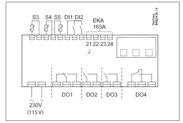
Power supply
230 V a.c.
Sensors
S3 and S4 are thermostat sensors.
A setting determines whether S3 or S4 or both of them are to be used.
S5 is a defrost sensor and is used if defrost has to be stopped based on temperature.
Digital On/Off signals
A cut-in input will activate a function. The possible functions are described in menus o02 and o37.
External display
Connection of display type EKA 163A (EKA 164A).
Relays
The general uses are mentioned here. See also page 6 where the different applications are shown.
- DO1: Refrigeration. The relay will cut in when the controller de-mands refrigeration
- DO2: Defrost. The relay will cut in when defrost is in progress
- DO3: For either fans or refrigeration 2
Fans: The relay will cut in when the fans have to operate Refrigeration 2: The relay will cut in when refrigeration step 2 has to be cut in - DO4: For either alarm, rail heat, light or hotgas defrost Alarm: Cf. diagram. The relay is cut in during normal opera-tion and cuts out in alarm situations and when the controller is dead (de-energised)
Rail heat: The relay cuts in when rail heat is to operate
Light: The relay cuts in when the light has to be switched on Hotgas defrost: See diagram. The relay will cut out when defrost has to be done
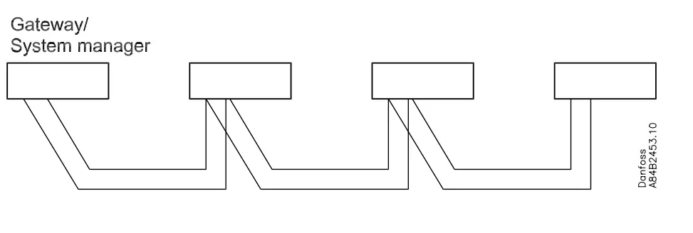
Data communication
The controller is available in several versions where data com-munication can be carried out with one of the following systems: MOD-bus or LON-RS485.
If data communication is used, it is important that the installation of the data communication cable is performed correctly.
See separate literature No. RC8AC…
Electric noise
Cables for sensors, DI inputs and data communication must be kept separate from other electric cables:
- Use separate cable trays
- Keep a distance between cables of at least 10 cm
- Long cables at the DI input should be avoided
Coordinated defrost via cable connections
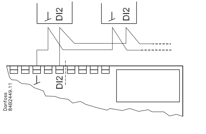
The following controllers can be connected up in this way:
- AK-CC 210, AK-CC 250, AK-CC 450,
AK-CC 550 - Max. 10.
Refrigeration is resumed when all controllers have “released” the signal for defrost.
Coordinated defrost via data communication
Data
| Supply voltage | 230 V a.c. +10/-15 %. 2.5 VA, 50/60 Hz | ||
| Sensors 3 pcs off either | Pt 1000 or
PTC 1000 or NTC-M2020 (5000 ohm / 25°C) |
||
|
Accuracy |
Measuring range | -60 to +99°C | |
|
Controller |
±1 K below -35°C
±0.5 K between -35 to +25°C ±1 K above +25°C |
||
| Pt 1000 sensor | ±0.3 K at 0°C
±0.005 K per grad |
||
| Display | LED, 3-digits | ||
| External display | EKA 163A | ||
|
Digital inputs |
Signal from contact functions Requirements to contacts: Gold plating Cable length must be max. 15 m
Use auxiliary relays when the cable is longer |
||
| Electrical con- nection cable | Max.1,5 mm2 multi-core cable | ||
|
Relays* |
CE
(250 V a.c.) |
UL *** (240 V a.c.) | |
| DO1.
Refrigeration |
8 (6) A | 10 A Resistive 5FLA, 30LRA | |
| DO2. Defrost | 8 (6) A | 10 A Resistive 5FLA, 30LRA | |
|
DO3. Fan |
6 (3) A |
6 A Resistive 3FLA, 18LRA
131 VA Pilot duty |
|
|
DO4. Alarm |
4 (1) A
Min. 100 mA** |
4 A Resistive
131 VA Pilot duty |
|
|
Environments |
0 to +55°C, During operations
-40 to +70°C, During transport |
||
| 20 – 80% Rh, not condensed | |||
| No shock influence / vibrations | |||
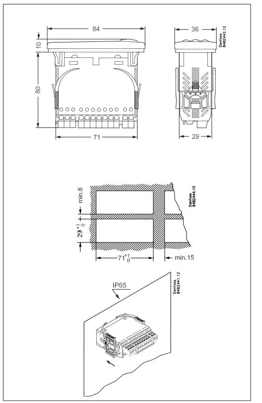
| Density | IP 65 from front.
Buttons and packing are imbedded in the front. |
||
| Escapement reserve for the clock |
4 hours |
||
| Approvals
|
EU Low Voltage Directive and EMC demands re CE- marking complied with
LVD tested acc. EN 60730-1 and EN 60730-2-9, A1, A2 EMC tested acc. EN61000-6-3 and EN 61000-6-2 |
||

- * DO1 and DO2 are 16 A relays. The mentioned 8 A can be increased up to 10 A, when the ambient temperature is kept below 50°C. DO3 and DO4 are 8 A relays. Max. load must be kept.
- ** Gold plating ensures make function with small contact loads
- *** UL-approval based on 30000 couplings.
Danfoss can accept no responsibility for possible errors in catalogues, brochures and other printed material. Danfoss reserves the right to alter its products without notice. This also applies to products already on order provided that such alternations can be made without subsequential changes being necessary in specifications already agreed.
All trademarks in this material are property of the respecitve companies. Danfoss and Danfoss logotype are trademarks of Danfoss A/S. All rights reserved.
User Guide RS8EP602 © Danfoss 2018-11
FAQ
- Q: How many thermostat sensors can be connected to the AK-CC 210 controller?
A: Up to two thermostat sensors can be connected. - Q: What functions can the digital inputs serve?
A: The digital inputs can be used for case cleaning, door contact with alarm, starting a defrost cycle, coordinated defrost, change-over between two temperature references, and retransmission of contact position via data communication.
Documents / Resources
 |
Danfoss AK-CC 210 Controller For Temperature Control [pdf] User Guide AK-CC 210 Controller For Temperature Control, AK-CC 210, Controller For Temperature Control, For Temperature Control, Temperature Control |