Haoru Tech ULM3-PDOA Positioning Module

Specifications
- Product Name: ULM3-PDOA
- Manufacturer: Haorutech co. Ltd
- Core Chip: Decawave DWM3220
- MCU: STM32F103CBT6 or GD32F103CBT6
- Features: Precise ranging, indoor positioning, high-speed data communication
- Integration: OLED display
Product Usage Instructions
System Installation and Utilization
To install and utilize the ULM3-PDOA module, follow these steps:
System Installation and Notes
- Follow the provided guidelines for physical installation of the module.
- Ensure proper power supply to the module.
Connecting to PC
- Connect the ULM3-PDOA module to a PC using the USB port for power supply and data transmission.
Communication Protocol
The ULM3-PDOA module uses a specific communication protocol for data transmission:
Uplink Data Protocol
- Refer to the user manual for details on the uplink data protocol used by the module.
Frequently Asked Questions (FAQ)
- Q: What are the main features of the ULM3-PDOA module?
A: The ULM3-PDOA module features precise ranging, indoor positioning capabilities, high-speed data communication, and an integrated OLED display. - Q: How can I use the ULM3-PDOA module for positioning applications?
A: The ULM3-PDOA module can act as an anchor in combination with ULM3 or ULM3-SH tags to create a single-anchor PDOA positioning system or following system.
User Manual ULM3-PDOA
Haorutech co. Ltd

Introduction
ULM3-PDOA is a PDOA positioning module, based on the latest DW3000 series chip. Core UWB module of ULM3-PDOA is official Decawave DWM3220, and MCU is STM32F103CBT6 (or GD32F103CBT6 which based on the price fluctuation and batches difference). ULM3-PDOA can be used for precise ranging, indoor positioning and other high-speed data communication applications. ULM3-PDOA also integrates the OLED display. All the features make ULM3-PDOA easy to use, with high precision and small size.
For positioning applications, ULM3-PDOA module normally plays the role as an anchor, and the ULM3 modules and ULM3-SH can be tags, which can form a single-anchor PDOA positioning system or following system. 
DW3000 features
- Ultra-low power consumption
- Through comprehensive optimization, DW3000 series can make power consumption 5 times lower than DW1000 by reducing peak current, frame duration and startup time. The power consumption of DW3000 is lower than BLE, and more friendly to low power standby duration.
- Excellent security
- DW3000 supports for the new IEEE802.15.4z standards, and preamble encryption.
- High compatibility
- DW3000 is compatible with the latest IEEE802.15.4z. After developing of FiRa compatible code, it supports main commercial mobile phones available in the market.
- Highly-integrated
- By integrating baluns, capacitors and other components inside the chip, DW3000 reduced its size by reducing the number of external components from 30+ to 10.
- PDOA with single chip
- DW1000 series requires two DW1000 chips to realize PDOA with the same clock source. But DW3x20 supports external double antennas, which can measure the arrival phase difference. The cost, size and power can be reduced by using one single chip.
Module selection
Table 3-1 Comparison of Module Features
| No. | Type | Main features |
| 1 | ULM3 | Official DWM3000 module, display integrated, 40m |
| 2 | ULM3-SH | Wristband, battery inside, motion detection, 40m |
| 3 | ULM3-PDOA | PDOA anchor, angle detection, single base positioning, car-following, 40m |
Above are the related module based on DW3000 core chip, which can be combined used.
Product parameters

Table 4-1 ULM3-PDOA Module Parameters
| Category | Parameter |
| Power | DC5V external power supply |
| Maximum Detection Range | 40m (open area) @6.8Mbps |
| MCU | STM32F103CBT6 (GD32F103CBT6) |
| Display Onboard | 0.6 inch OLED |
| Module Size | 41*67.5mm |
| Ranging Accuracy | ±5cm |
|
Detect Angle |
120°(centralized by the module, -60°
~+60°) |
| Angle Accuracy | ±5 |
| Working Temperature | -20~70℃ |
| Communication Mode | USB to serial port / TTL serial |
| Data Update Frequency | 100Hz (MAX, adjustable) |
| Frequency Domain | 6250-8250MHz (CH5/CH9) |
| Bandwidth | 500MHz |
| Type of Antenna | PCB double antenna |
| Emission power spectral density
(Programmable) |
-41dBm/MHz |
| Communication Rate | 6.8Mbps |
Module interfaces
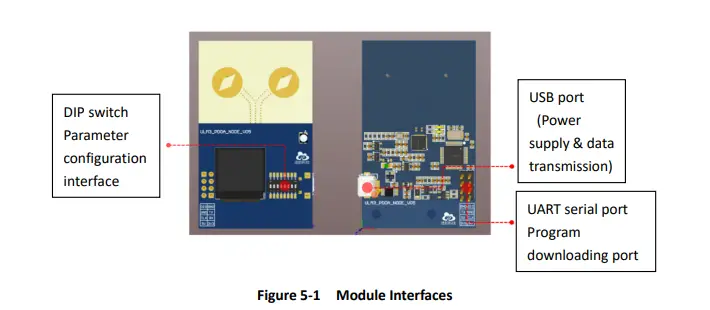
USB port (power supply & data transmission)
The port can be connected to a standard 5VDC module such as a charging bank or other 5V power adapters. It can also be connected to the USB port of a computer for power supply and data transmission and data display on the computer.
Program downloading port
The port is the SWD debugging interface of STM32 microcontroller, which can be used for program downloading, simulation debugging, etc. It is mainly used for embedded program development and firmware update, and it can be used with the ST-LINK downloading tool.
UART serial port
ULM3-PDOA module can connect to PC or Raspberry PI and other systems through USB port for data transmission, but also has UART serial port (TTL) on board, which can connect to other microcontrollers, Arduino and other devices for data transmission and secondary development. While Connecting, the TX pin of ULM3-PDOA should be connected to the RX pin of the target module, and the GND pin of the two modules should be connected directly. 
LED indicator
On board RGB indicator indicates the current system status.
Table 5-1 Indicator Status Description
|
Working Status: Tag |
Start ranging and successfully get response from 1 or more anchors, and establish ranging communication. | GREEN LED BLINK |
| Start ranging but get no response from anchors. | RED LED BLINK | |
|
Working Status: Anchor |
Successfully establish a ranging connection with any tag. | LIGHT BLUE LED BLINK |
| No tag connected. | LIGHT BLUE LED NOT BLINK (ON or OFF) |
ULM3-PDOA module integrated the 8-bit DIP switch. The following figure 5-3 lists the switch configuration attributes. Users can easily configure the communication frequency, role, ID, and built-in Kalman filter switch of the module.
|
S1 |
S2* (Maximum number of tags and communication
period) |
S3* (Increase the external current) |
S4(Role) |
S5-S7 (Device address) |
S8 (Kalman filter) |
|
| Maximum number of | ||||||
| ON | Reserved | tags: 1 Total communication | ON | Anchor | ON | |
| period:10ms | Device address | |||||
| Maximum number of | 000-111 | |||||
| OFF | Reserved | tags: 10 Total communication |
OFF | Tag | OFF | |
| period:100ms |
The default configuration of the system:
- Maximum number of tags:10tags
- Update period:100ms (10Hz)
- External current increase:open
- Kalman filter:open.
* Note: Due to the low power consumption of DW3000 series modules, most of the power banks will actively turn off the external power supply when the load current is low. This will make the module reboot again and again. S3 increases the external current to actively increase the current of the module, which helps the power bank to maintain continuous output.
On Board OLED Display

Table 5-3 Display Information Description
| Example | Description |
| V75 | Firmware Version |
| 4A10T | Maximum 4 anchors and 10 tags |
| 10HZ | Data update rate(current mode) |
| 100ms | Current data update period(=1/ Data update rate) |
| 6.8M | Current UWB air rate is 6.8Mbps(Alternative option: 110k) |
| CH5 | Current UWB channel is CH5(Alternative option: CH2 Channel 2) |
| Anc:0 | Current module is anchor, ID=0 (Alternative option: Tag) |
| K | Kalman filtering is enabled (no display: disabled) |
System installation and utilization
System installation and notes
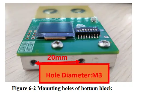
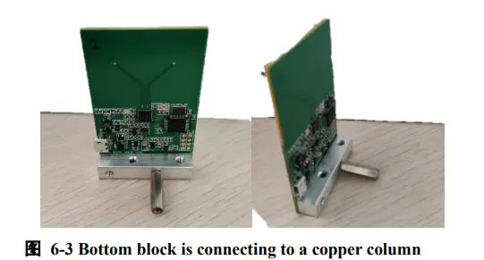
The antenna of ULM3-PDOA module is oriented towards the positioning tag. The module is powered by an external 5V power supply. There is a square block fixed on the bottom of the module, which can be fixed on the UGV or the desktop with M3 screws. Also, it can be connected to a copper column to increase the supporting force to placed on the horizontal platform.
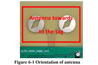
The anchor was set as the coordinate point (0,0) to establish the coordinate system, and the Y axis was directly in front of the anchor. The tag positioning and AOA calculation could be completed from -60°to +60°.  Matters need attention:
- The tag should be positioned within the correct coverage range of anchor, otherwise there may occur some errors, such as inaccurate positioning;
- The antenna surface of anchor should be orientated towards the tag;
- The distance between the anchor and the tag should be greater than 1 meter;
- The anchor should be installed in an open area;
- There should be no occlusion between the tag and the anchor, especially no steel plates and other metals.
Connecting to PC  For the initial utilization, CH340 driver should be installed at first. After identifying the serial port on the PC, please open the PC software, select the serial port, and click “Connect” button to complete module connection and data communication.
 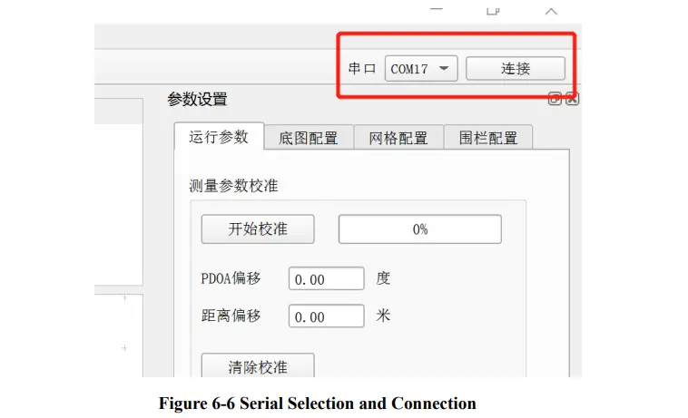 After connecting to the PC and switch on the tag successfully, the PC software can display the tag information and positioning trace.
 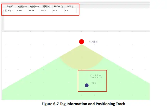 For more details about the utilization of system deployment, please download the <HR-RTLS1-PDOA UserManual-EN> to get more information.
Download HR-RTLS1-PDOA UserManual: http://rtls1.haorutech.com/download/HR-RTLS1-PDOA UserManual-EN.pdf
Communication protocol
Uplink data protocol
- The uplink data protocol is the data uploaded actively by the UWB module through the serial port.
- Serial communication baud rate: 115200bps-8-n-1
Communication protocol:
- MPxxxx,tag_id,x_cm,y_cm,distance_cm,RangeNumber,pdoa_deg,aoa_deg,distance_ offset_cm,pdoa_offset_deg\r\n
- Serial communication data example: MP0036,0,302,109,287,23,134.2,23.4,23,56
Table 7-1 Serial Communication Protocol Description
| Content | Example | Description | |||||
| MPxxxx | MP0036 | Head of the data packet, 0036 is the number of all data bytes except MPxxxx, including the ending \r\n, which is fixed to 4 characters. If it is less than the length, fill up with 0. | |||||
| tag_id | 0 | The current tag ID | |||||
| x_cm | 302 | X coordinates of the tag, integers, units:cm | |||||
| y_cm | 109 | Y coordinates of the tag, integers, units:cm | |||||
| distance_cm | 287 | Direct distance between the anchor and the tag,
integers, units:cm |
|||||
| RangeNumber | 23 | Serial numbers of ranging,0-255 | |||||
| pdoa_deg | 134.2 | PDOA value, Float, units:degree | |||||
| aoa_deg | 23.4 | AOA value, Float, units: degree | |||||
| distance_offset_cm | 23 | Calibration value of direct distance between the
anchor and the tag, integers, units:cm |
|||||
| pdoa_offset_deg | 56 | Calibration
units:degree |
value | of | PDOA | value, | Float, |
| \r\n | Ending data | ||||||
Anchor Calibration
Due to the influence of welding, PCB manufacturing process and other factors, the RF transmission line of the two antennas of the ULM3-PDOA module will cause small errors, resulting in PDOA Angle deviation, which can be calibrated by the PC.
After the ULM3-PDOA module is successfully connected to PC and the tag location data is displayed, click the “Start calibration” button, place the anchor and tag at the same height as prompted, place the tag in front of the two antenna centers of the anchor, and measure the distance between the anchor and tag. It is recommended that the distance should be more than 2 meters.
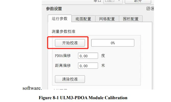 Fill the measured distance value into the PC software, and keep the position of the tag and anchor unchanged until the calibration progress bar rolls to 100%, which is when the calibration is completed.
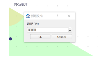 Figure 8-2 ULM3-PDOA Module Calibration
After the calibration is completed, the PC software prompts the calibration deviation, and the anchor will output calibration data according to this deviation. If you need to clear the calibration data, you can click the “Clear calibration” button to reset the deviation value and re-calibrate. 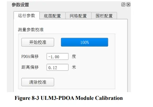
Shipping list
Shipping list of single ULM3-PDOA module: (Highly recommendation: purchasing more than 4 modules to get a whole positioning system.)
Table 9-1 Shipping List
| No. | Category | Number | Notes |
| 1 | ULM3-PDOA module | 1 | |
| 2 | Micro-USB data cable | 1 |
Development and learning files
List of development and learning materials we provide after purchasing:
Table 10-1 Documents
| No. | Category | File type |
| 1 | Quick guide of QT software |
| 2 | RTLS1-PDOA Bilateral ranging agreement | |
| 3 | ULM3-PDOA_UserManual | |
| 4 | RTLS1-PDOA _UserManual | |
| 5 | DW3000 UserManual by Qorvo | ZIP |
Documents / Resources
 |
Haoru Tech ULM3-PDOA Positioning Module [pdf] User Manual ULM3-PDOA Positioning Module, ULM3-PDOA, Positioning Module, Module |